Computer Aided Design
Softwares Used
Getting Started
I started this week by working out which part of the gloves would be the most benificial for me to design using CAD from scratch. I settled on a cuff which will harbour my IMU and circuit-board as this is something that I haven't looked at fabricating yet. I already have a finished glove textile from Rachel's workshop which i can work with for now, until i design my own pattern, I will need a cuff to work with this glove before I go on to develop sensoring and electronics designs. I also already have the material which I will make the cuff from, this can be laser cut so modelling it now will make it very easy for me to fabricate it at a later date.
My cuff will have two material layers so that wiring can be concealed inside it, and it will be able to harbour a battery, the IMU and circuit in concealed pouches created by the cutting between the two layers. This will require a design of three different 2D patterns, two for each layer of material and one for the adhesive which will stick the two layers together, avoiding components that will be inserted. These can then be layered to create a 3D visualisation after they have been seperately designed so that they function together as patterns.
Learning CAD
I had very little experience with any CAD software before starting this week, therefore my first step was to look through a number of different softwares and find the one that best suited my needs and was easiest to learn in a short space of time. I settled on Fusion 360 and watched this begginers tutorial on how to make an example component (see picture below), in order to become familiar with the software.
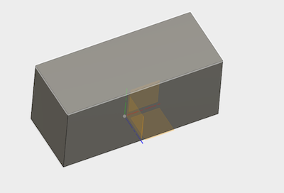
Very Basic
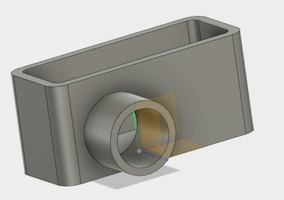
Starting to improve
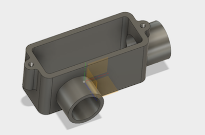
More advanced
After doing this i felt comfortable working basically in Fusion 360, yet i didn't want to make my model in it right away. This is because I will be cutting a pattern out of fabric, which is technically a 2D design transferred to 3D in production.
I learned Fusion in order to be able to create a realistic representation of what the cuff will look like, I then started to work with Inkscape, a software used to create vector images, in order to create accurate 2D designs of the patterns a will need to cut to create the cuff. To learn the basics of Inkscape I took a look at this tutorial which goes through the interface and explains how the software works. I then began to work on my pattern. My first work in Inkscape was very slow as it was hard to create accurate line measurements. This ended up being my first draft drawing.
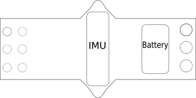
Failed Inkscape sketch
This did not prove accurate enough as the Inkscape software is not designed for CAD, it would have worked in a laser cutter but was not the shape I wanted it to be, nor did it allow for easy editing of components.
After this failure i quite literally went 'back to the drawing board' and drew an accurate sketch by hand using a ruler, pencil and pen, this was to become the basis of my next work 'in the box'.
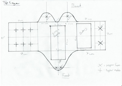
Drawn by hand
Final Designs
For accurately drawing my sketch inside the computer I decided to sketch it in Adobe Illustrator, a software I hadn't previously wante to use as it isn't open source and I don't currently own it. This means all the work I do using it would have to be on-site at the lab, despite this it is the best software for what I'm doing due to it's accuracy and stability. I began to transfer my sketch into illustrator.
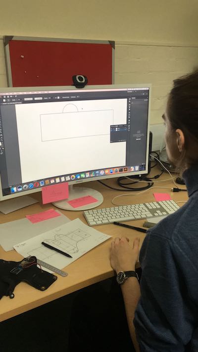
From paper to screen
Illustrator does have the option to scan in and vectorize an image from a drawing, however I didn't want to do this as I felt I should learn how to start drawing from scratch in Illustrator, my sketch was also had a few marks on the page from rubbings, so may have come out a little messy.
Once I had drawn in my pattern I created three variations as I will need to laser cut three different layers for the cuff: the top, the bottom and the glue to bind them together. Having two layers of material will allow me to conceal wires and to hold integral components such as the battery and IMU inside the cuff. I will eventually be using neoprene to make my cuff as it is durable, soft and can be laser cut and heat pressed (the glue is activated by heat). To create the pattern in Illustrator I used the rectabgle tool to form the main base, the curve tool for the outer parts, the rectangle again for the IMU and battery and then the ellipses tool for the poppers. Poppers with an X are female and those with a + are male. I then tidied up the skteches with grouping and the scissor tool. They eventually looked like this (these models are facing with the front downwards as this is how i drew the initial sketch):

top layer

glue layer

bottom layer
The cuff contains space for the IMU, circuit-board and battery, as well as functionality for people who may want to go even further and make sensory equipment that goes up the arm, with snaps attached to the back. I may swap out the connecting poppers on the cuff for velcro at a later date if this proves to be more user friendly.
After I had finished each layer I attempted to export a .dxf file from Illustrator, however it gave me an unexplained error message. In order to work around this I knew that Rhino could open .ai files so I saved as this and exported as a .dxf from there into Fusion 360. At this point I also had a look at Rhino 3D design software for the task I needed to complete, however I find Fusion more user friendly for simple purposes, I may have to use Rhino at a later date when modelling more complex things such as enclosures for hardware or storage/display devices. The 3D model from Fusion can be seen below. It will be thinner in rpoduction, I just did not have the fabrics with me to measure their depth when I created the model.
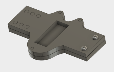
3D Model