Process
- Decisions
- Brainstorming
- Crankie Design and Fabrication
- Electronics
- Puppet Design and Fabrication
- Assembly
Decisions
With a lot of documentation to catch up on, I hemmed and hawed quite a bit on my final project.
- Original idea: storytelling lantern or crankie
- Finish the cat wheel
- Make the SUP and add accelerometer to track distance and speed
Ultimately, after consulting with my instructors, I decided that my first (and favorite for a final project), was the best way to go.
I want to incorporate light/shadow and sound. I hadn't developed the storytelling lantern idea any further than what essentially would be interchangeable laser-cut parts but thought I could have some sort of sensor that would detect patterns (color, light) as the scroll was turned. This seemed like a more promising route.
Brainstorming Ideas
Input
Include a sensor to detect pattern that will translate to specific light and sound sequences
- QR codes
- Infrared Sensor with black/white patterns
- RGB Sensor with color patterns
- commerical products: 1838B IR Receiver, TCS3200 RGB Color Sensor
Output
Sound
- Play programmed sound stored on MicroSD card through speaker
- Enable recording of child-generated sound for storage and playback
- commercial products: SoundDuino, Wave Shield
Light
- Programmable RGB LED strips lining the interior of the box
- Programmable RGB LED bulb at base of the box
Programming/Interface
- Push buttons to record and play sound
- Enable children to program their own sound and light patterns using Scratch
Given the time crunch and the necessity of having light for the type of shadow-play crankie I wanted to make I decided to prioritize light.
Electronics
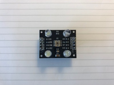
RGB Color Sensor Board
Testing TCS3200
TAOS makes a color sensor chip, the TCS3200 (datasheet), that is popular with Arduino enthusiasts. There are several companies that make a cheap board with a TCS3200 already hooked up for easy evaluation. I purchased one of these boards from Amazon:
I connected the Arduino to the TCS3200 like this:
| Arduino pin | TCS3200 pin |
|---|---|
| 4 | S0 |
| 5 | S1 |
| 6 | S2 |
| 7 | S3 |
| +5V | VCC |
| GND | OE_N, GND |
With help from a YouTube tutorial, I made a simple program to test the color sensor board:
unsigned int pulse_width = 0;voidvoid
This code uses the pulseIn() function to measure the pulse width of the color sensor output. It also uses the serial monitor of the Arduino to print the pulse widths of the various R (red), G (green), and B (blue) sensors to the screen.
I hooked the Arduino up to the TCS3200 board with the sketch loaded. The four LEDs lit up:
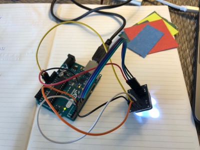
Once the Arduino sketch is loaded then the sensor board powers up and outputs R, G, and B values to the serial monitor on the screen. Here's what it did when I put the sensor against red paper:
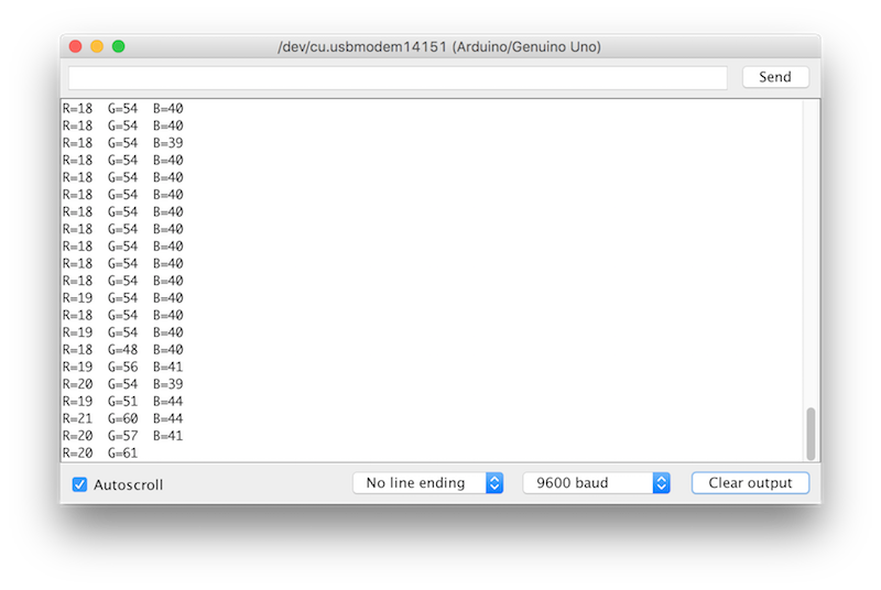
The number was smallest for red, which means the sensor is detected the red color! Then I repeated the test for the different colors of paper that I had. I also used black and white for comparison:
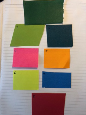
| Paper color | R | G | B |
|---|---|---|---|
| White | 12 | 15 | 11 |
| 1 Green | 68 | 68 | 65 |
| 2 Light Green | 27 | 32 | 44 |
| 3 Blue/Green | 63 | 62 | 43 |
| 4 Pink | 9 | 38 | 21 |
| 5 Orange | 11 | 29 | 35 |
| 6 Yellow | 13 | 16 | 26 |
| 7 Blue | 49 | 39 | 20 |
| 8 Red | 21 | 68 | 48 |
| Black | 100 | 147 | 108 |
From the numbers in bold it seems like the sensor had difficulty detecting the color green by itself. I may have to avoid using green in my project to remedy this.
TCS3200 with Barduino
Next step was to use this sensor board with the Barduino. Ultimately, I'd like to use two boards modified from the original Barduino design that will communicate to each other via serial bus- one for the RGB sensor and one to control my LEDs.
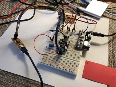
I put the RGB sensor board on a breadboard to make wiring easier. I then hookup the Barduino using this configuration:
| Barduino pin | Connection |
|---|---|
| 5 (output) | FTDI cable RX |
| 6 (output) | TCS3200 pin S2 |
| 7 (output) | TCS3200 pin S3 |
| 8 (input) | TCS3200 pin OUT |
I connected the FabISP board to the Barduino through the 6-pin connection.
I modified the code for the Barduino to use the SoftwareSerial library because the Barduino board I made doesn't have headers attached to the pins for hardware software (D1 and D2) and I wasn't particularly inclined to 1. solder to the microcontroller again as I had for networking or 2. wait to get headers to test:
SoftwareSerial ;unsigned int pulse_width = 0;voidvoid
After uploading the sketch, it worked! Here it is being tested with the red paper:
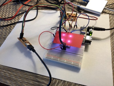
I got R, G, and B output to the serial monitor on the FTDI cable as before. Next, I took the data again using my color papers:
| Paper color | R | G | B |
|---|---|---|---|
| White | 13 | 16 | 12 |
| 1 Green | 75 | 76 | 72 |
| 2 Light Green | 30 | 35 | 47 |
| 3 Blue/Green | 72 | 66 | 45 |
| 4 Pink | 11 | 42 | 22 |
| 5 Orange | 12 | 32 | 39 |
| 6 Yellow | 16 | 19 | 30 |
| 7 Blue | 59 | 43 | 22 |
| 8 Red | 24 | 75 | 52 |
| Black | 130 | 175 | 126 |
The numbers were slightly different, perhaps due to the sensor board being flipped upside down, but the setup worked as expected overall.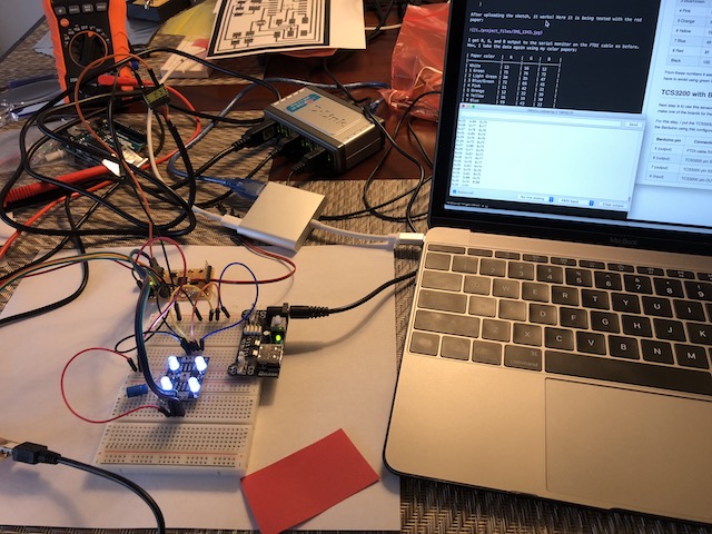
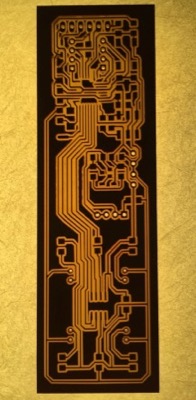
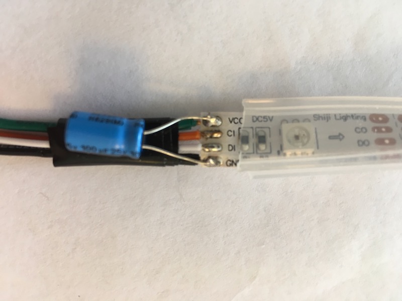
My RGB Board- Imliduino
I started with a Barduino and added the TCS3200, four LEDs, and four resistors for the LEDs. I used the same physical spacing as on the TCS3200 I tested earlier. I also removed the power jack from the original Barduino design and replaced it with a 4-pin header, so that I could more easily connect any power source to it. In the end, I had to add a few additional 0 Ohm resistors in order to connect all of my traces.
Schematic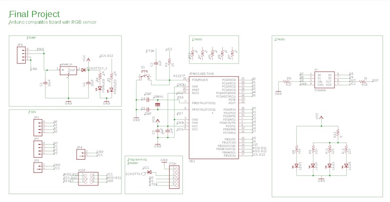
Layout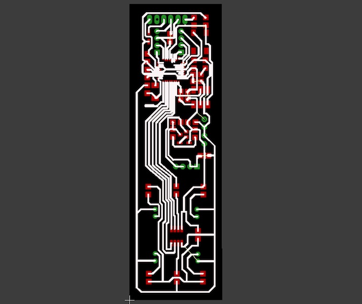
I used Gimp to set up the traces and cut/through-hole files.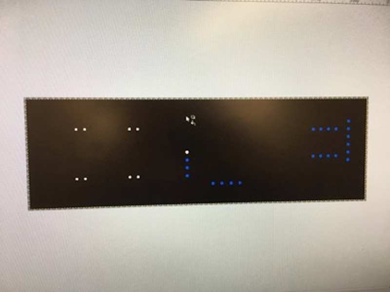
On my first attempt, the PCB lifted off of the sacrificial material 1/3 of the way through milling. I adjusted my depth of cut slightly and added a lot of pressure when affixing the next pcb piece to the sacrificial material. Even after we changed the sacrificial material, our machine still doesn't cut larger PCBs evenly. Although the Imliduino is smaller in overall profile than my modified Satshakit board, it still is quite long.
Here is the board after soldering the components:
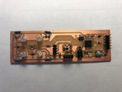
Unfortunately, I didn't bring the correct 100 Ohm resistors home (I brought 100k instead), so I had to solder on some regular resistors instead of the surface mount resistors.
I first ran a smoke test and then used my FabISP to burn the bootlaoder. The board worked after being powered up. I tested the board by uploading the Blink sketch from the Arduino IDE examples and making sure that the red pin 13 LED blinked properly:
Next I wanted to make sure that the color sensor worked similar to before with the colored paper:
LED Light Strip First Try
I plan to use an LED light strip to make the color light sequences for the Crankie. The Adafruit DotStar Digital LED strip looked promising. I found a very helpful DotStar tutorial on YouTube. For the DotStar, you are supposed to connect your wires to one end, and then the signals travel down the strip to the other end in the direction of the arrow. After watching the tutorial, it was evident that on the DotStar I received, the company had connected wires to the wrong end of the strip so I soldered wires to the reverse end:
Next, I downloaded the Adafruit DotStar Arduino Library and added it to the Arduino IDE as we have done with other libraries. I then loaded the example file strandtest and uploaded it to an Uno board. As it says in the comments of strandtest, I connected the data pin and clock pin of the Dotstar to pins 4 and 5 on the Uno board. I also connected power (5V) and ground.
// Simple strand test for Adafruit Dot Star RGB LED strip.// This is a basic diagnostic tool, NOT a graphics demo...helps confirm// correct wiring and tests each pixel's ability to display red, green// and blue and to forward data down the line. By limiting the number// and color of LEDs, it's reasonably safe to power a couple meters off// the Arduino's 5V pin. DON'T try that with other code!// Because conditional #includes don't work w/Arduino sketches...// COMMENT OUT THIS LINE FOR GEMMA OR TRINKET//#include <avr/power.h> // ENABLE THIS LINE FOR GEMMA OR TRINKET// Number of LEDs in strip// Here's how to control the LEDs from any two pins:Adafruit_DotStar strip =;// The last parameter is optional -- this is the color data order of the// DotStar strip, which has changed over time in different production runs.// Your code just uses R,G,B colors, the library then reassigns as needed.// Default is DOTSTAR_BRG, so change this if you have an earlier strip.// Hardware SPI is a little faster, but must be wired to specific pins// (Arduino Uno = pin 11 for data, 13 for clock, other boards are different).//Adafruit_DotStar strip = Adafruit_DotStar(NUMPIXELS, DOTSTAR_BRG);void// Runs 10 LEDs at a time along strip, cycling through red, green and blue.// This requires about 200 mA for all the 'on' pixels + 1 mA per 'off' pixel.int head = 0, tail = -10; // Index of first 'on' and 'off' pixelsuint32_t color = 0xFF0000; // 'On' color (starts red)void
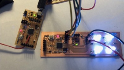
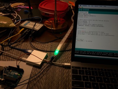
Immediately after connecting the Uno, the LED strip started to light up in a moving show of colors. The colors were very bright, and so I think it will work well in my crankie project.
Serial Communication
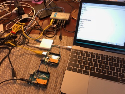
For the project I'm going to have a sensor board connected by a serial wire to a receiver board that drives the DotStar LED strip. As we know from the DotStar example, code, it will take a 6-digit number that corresponds to the light color. The first two digits set the red level, second two set the green level, and the last two set blue level. I want to be sure that I can send three numbers over a serial connection from one microcontroller, and interpret it on the other. For this exercise, I use two Arduino Unos instead of the boards I designed, because I don't want to damage my boards from too frequent plugging/unplugging.
I started with example code found at this website where she sends both temperature and humidity data from one Arduino board to another. Here code is available here:
Si-7021-serial-sender-receiver-sketches
Below is my code for the sending Arduino Uno. Some new functions to me are:
- sprintf() - used to make a three-digit string even if the number was only one or two digits
- strcat() - puts two strings together
- memset() - used for erasing a string
Code:
// Define TCS3200 pins// for frequency scaling// for frequency scaling// used to select RGB// used to select RGB// output of TCS3200 to microcontroller input 10char sendString[20]; // string that is sent via serialchar redString[4]; // string that represents red levelchar greenString[4]; // ...green levelchar blueString[4]; // ...blue level// These below will be replaced by true readings from the TCS3200unsigned int pulseWidthRed = 17; // pulse width of red sensorunsigned int pulseWidthGreen = 254; // ...green sensorunsigned int pulseWidthBlue = 9; // ...blue sensorvoidvoid
Here is the code for the receive Arduino Uno:
int incomingByte = 0;unsigned int redLevel;unsigned int greenLevel;unsigned int blueLevel;String receiveString; // string I receiveString redString; // string to store red levelString greenString; // ...green levelString blueString; // ...blue levelvoidvoid
I use the serial monitor on the receive Arduino and get the following output, which shows that it is working and properly displaying the R, G, and B levels (17, 254, and 9) as sent from the send Arduino:
LED Light Strip Revisited
Next, I want to try programming different colors and sequences on the light strip to see how it works. I started again with the strandtest code. That code is a bit complicated, but it basically lights up 10 pixels at a time a specified color, and makes them move down the light strip. The important function in the code is strip.setPixelColor() function. I found information on this function in the Adafruit_Dotstar.h file. This line tells you how to use the function:
The first number looks like the pixel you are trying to set, and the next three numbers are the RGB values. To test this function, I made a very simple version of strandtest.
// Here's how to control the LEDs from any two pins:Adafruit_DotStar strip =;voidvoid
All this is supposed to do is set the first pixel (0) in the strand red, because I programmed the colors as (255,0,0), which I assume is red-green-blue. However, the pixel lit up green:
Also strangely, on the line that strip(() is defined, there is an argument DOTSTAR_BRG, which seems to indicate that the order should be blue-red-green, which doesn't match up with what I see either. After trying different combinations, I found that the true order of arguments to the strip() function, is green-red-blue. The easiest thing to do is just to make sure that when I use the strip() function, I give the colors in that order.
Since for my project I want to make many lights light up and change color at the same time, I need to make a loop that will make all the pixels the same color. I used a while loop to do this:
// Here's how to control the LEDs from any two pins:Adafruit_DotStar strip =;voidvoid
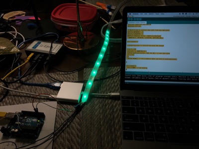
This successfully lit up the first 10 pixels to be green:
I then decided to make my own function that I could use later to simply turn all of the pixels (set by NUMPIXELS) a certain color. This will come in useful for when my LED board receives the color information from the sensor board, and then I can just use my new function to set the colors on the DotStar. Importantly, I have made sure to change the order of the arguments so that I am programming in red-green-blue order:
void
I also want a function that changes the color of the DotStar gradually, rather than abruptly because it is a little bit jarring for the user of the crankie to see the color go immediately from say, red to green instantly. There should be a smooth transition from red to green. The function needs to have two sets of red-green-blue arguments:
void
Let's take the red level for example. Once I know fromRed and toRed, I can subtract fromRed from toRed and divide it by the number of steps (numSteps) I want to take during the transition. Important to note that changeRed can be a negative number, in the case that I am going from a more red color to a less red color.
changeRed = (toRed - fromRed)/numSteps;
This didn't exactly work though, because the numbers are all integer types, so the division doesn't work properly. But I do need changeRed to be an integer. This works better because if I make numSteps a float, then the answer of the division step will be a type float. And then the round() function will round the answer to the nearest integer:
changeRed = ;
Next, I need to make a loop that changes the color level by changeRed every time through the loop. Again I chose a while loop. I made a variable called keepGoing, that will determine whether the loop keeps going.
int keepGoing = 1;while (keepGoing)
Basically, what this does is first set all the pixels to some red level. It then sets keepGoing=0 and then checks to see if you have gone past the toRed level (either by stepping up or stepping down). If you're not past the toRed level, then it sets keepGoing=1 and you go through the loop again.
So I add this all to my new changeColor() function:
void
And then I run the function to go from dark to bright red and back to dark in the setup() function:
void
And the result is this:
As you can see, it kind of worked, but when the pixels get too near max brightness, they go suddenly dark, and then when they almost get dark, they go suddenly bright, and stay there. It turns out that my loop was allowing the red level to go slightly above 255, and even slightly below 0. I found searching the web, that I could fix this by using the constrain() function. So I added this lines to my function at the beginning of the while loop, to keep the level between 0 and 255:
redLevel = ;
After doing that, my function works properly. I also decreased the step size, and the delay between steps to make it fade more gradually:
After adding lines in the code to also do the green and blue colors, I now had all the pieces of functioning code I need to complete the project!
Two Boards to One
Once I had my crankie assembled, scroll loaded, and DotStar mounted, it became very clear that it was not necessary to have two separate boards for this project. The ends of the DotStar were very close to where I planned to mount the color sensor. I decided instead to have two networked boards to use just the Imliduino to control both the color sensing and LED display. Essentially, I combined the two sets of code into one:
// Emily St. Germain (stgermain.emily at gmail dot com)//// Fab Academy 2018 Final Project//// 2m strip has 60 lights// This below came from Dotstar strandtest// includes the library and the serial communication// Define pins to talk to Dotstar// Define TCS3200 color sensor pins// for frequency scaling// for frequency scaling// used to select RGB// used to select RGB// output of TCS3200 to microcontroller input 10// This came from the Dotstar example// inside 'strip' are functions to do things to DotstarAdafruit_DotStar strip =;// These below will be replaced by true readings from the TCS3200int pulseWidthRed; // pulse width of red sensorint pulseWidthGreen; // ...green sensorint pulseWidthBlue; // ...blue sensorint redLevel; // redLevel from 0-255int greenLevel; // greenLevel...int blueLevel; // blueLevel...int prevRedLevel = 0; // save the old redLevelint prevGreenLevel = 0; // ...greenLevelint prevBlueLevel = 0; // ...blueLevel// this function writes all the pixels to the RGB levels of the argumentsvoid// this function gradually changes the color from one to anothervoidvoidvoid
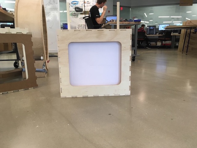
Crankie Design & Fabrication
I used the various plans shared on The Crankie Factory as guidelines for my box design and dimensions.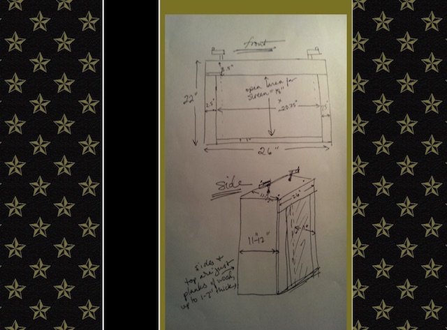
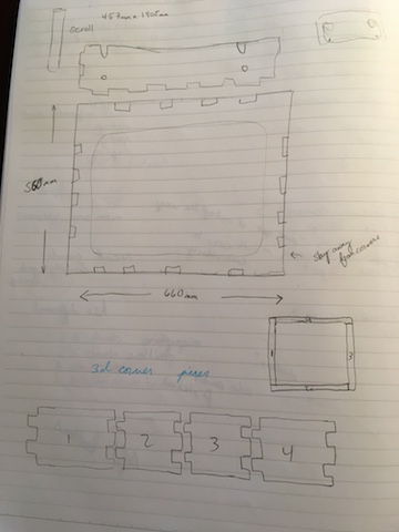
I made a 2D sketch of the individual sides of the box in Fusion360 and then found Luke Cyca's plug-in to create a tabbed box. I planned to use the 0.5" plywood we have in the Lab and set this as a parameter for "thickness" in my design. I pinned my sketches onto the respective faces of the box. Finally, I cut the holes for the screen and dowels.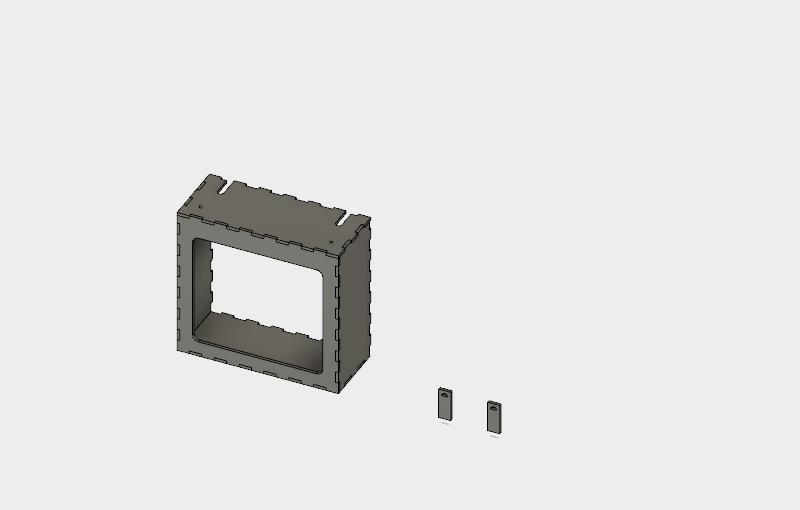
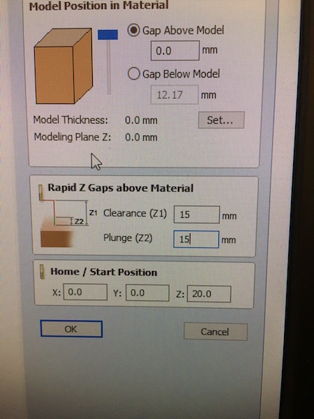
I exported my Fusion360 design file to .stl format for use in VCarve. In VCarve I first set my job size, material thickness, and units. I repositioned my components to use the material efficiently and started creating toolpaths.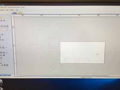
For the etching and cutting toolpaths I added tabs.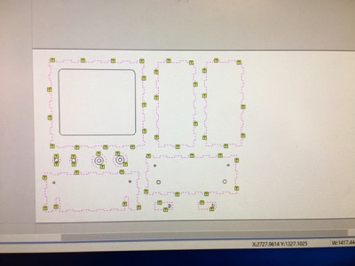
For the cutting toolpaths I also added dogbone fillets. I realized after I'd cut all my pieces however that my dogbones were set to be far smaller than the tool diameter. This meant that after cutting I had to go into the corners with a dremel to create dogbone fillets manually.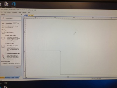
The ShopBot was still acting finicky- so I sacrificed nicely finished pieces in some cases (downcut followed by upcut) in hopes of getting finished cuts.
- Drill holes
- Downcut etching for scroll holders and positioning markers
- Downcut cutting for interior of front-piece (inside cut)
- Downcut cutting for all other pieces (outside cuts)
I noticed right on my first cut that there was a problem because my toolpath that was supposed to cut away half the material cut most of it.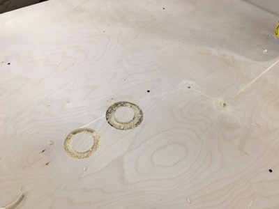
We've had similar problems with the z dropping or the tool "forgetting" where it is in space-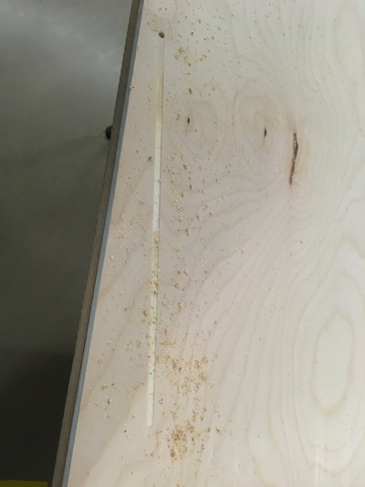
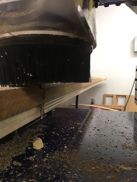
so while disconcerting, this wasn't particularly surprising.
One fix was to change the units I was working in on ShopBot to match my VCarve file units (mm). Additionally, the measurement of the z plate needed to be reset in the tool settings.
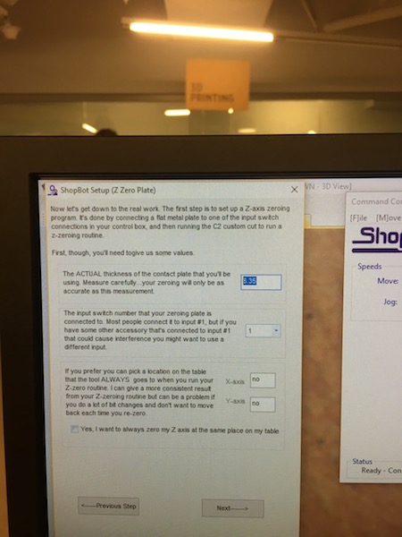
As a safety, I also reset the safe z position from 5mm above the material to 15mm on all of my toolpaths.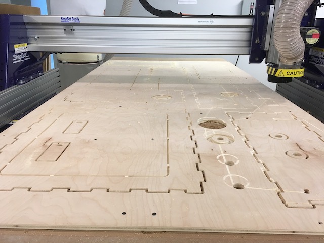
Once everything was cut I chiseled out the tabs from the larger material and started rough assembling.
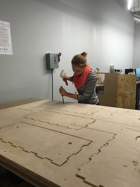
Ultimately I needed to recut the top-piece as I'd accidentally cut a top piece with the same teeth profile of the bottom.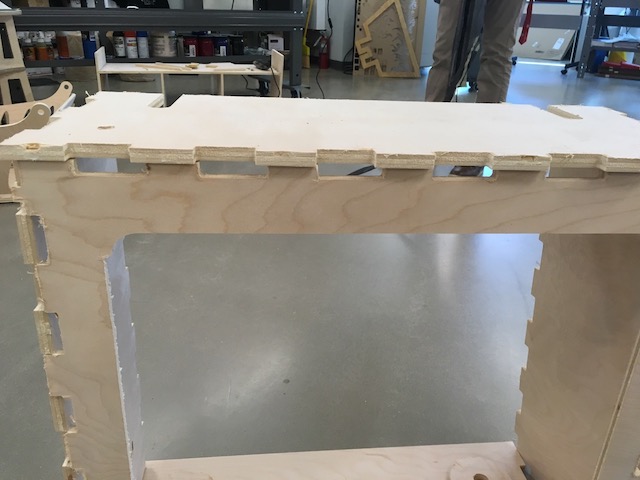
Later, I also realized that although my "stage" opening fit my scroll exactly, I didn't take into account that the scroll would be set back from the opening and light from the bulb would shine around the edges. I ended up redesigning and cutting a new front-piece as well.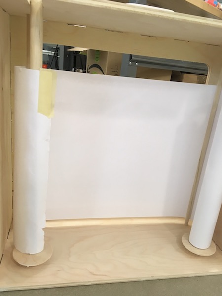
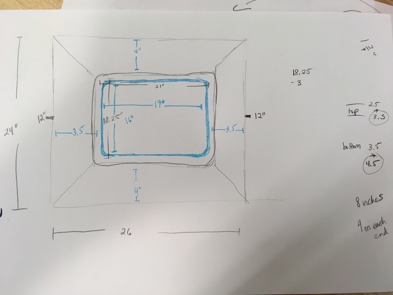
This time around I did the frontpiece in cardboard first to double check that sizing was correct.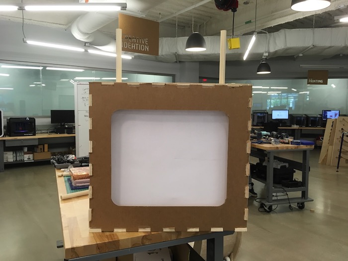
Finished crankie box