Week 3
Computer-controlled cutting
Assignment
Group
• Characterize your lasercutter, making test part(s) that vary cutting settings and dimensions.
Individual• cut something on the vinylcutter design, lasercut, and document a parametric press-fit construction kit, accounting for the lasercutter kerf, which can be assembled in multiple ways.
Lasercutter test
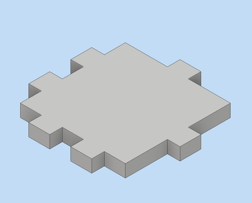
I did a design to test the lasercutter at first as shown.
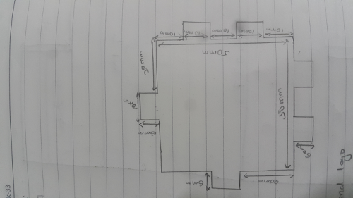
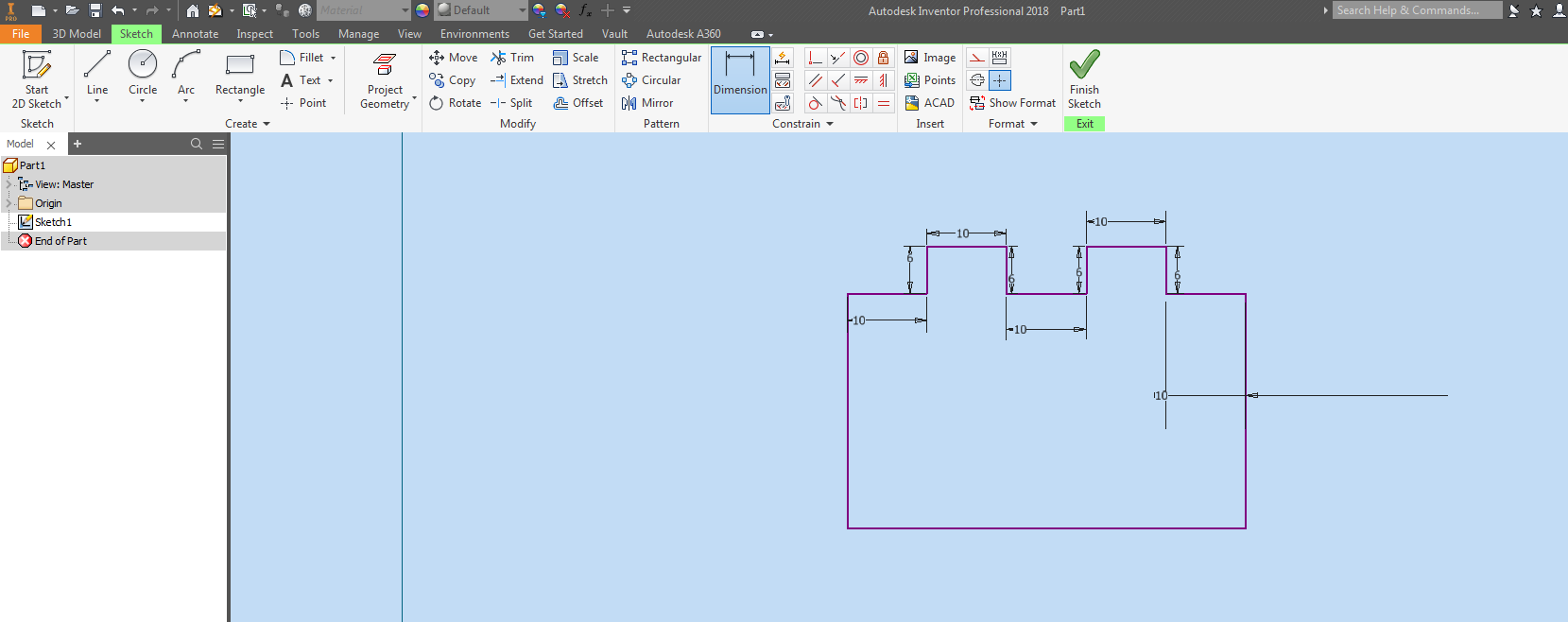
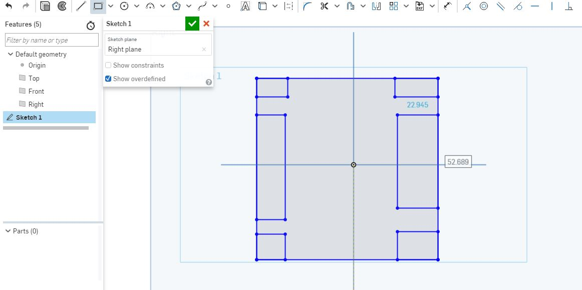
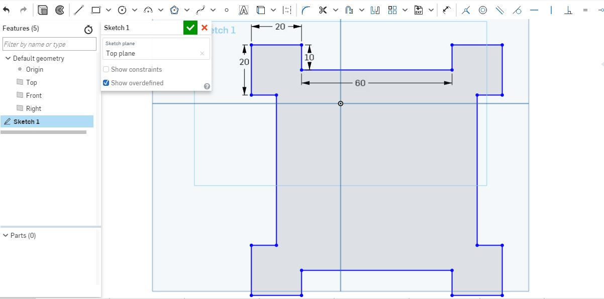
I decided to use inventor to design it as continuation to learn how to use it. I started with a 2D design. I did a large rectangle then smaller ones protruding outside. I trimmed off the excess lines then I gave them measurements.
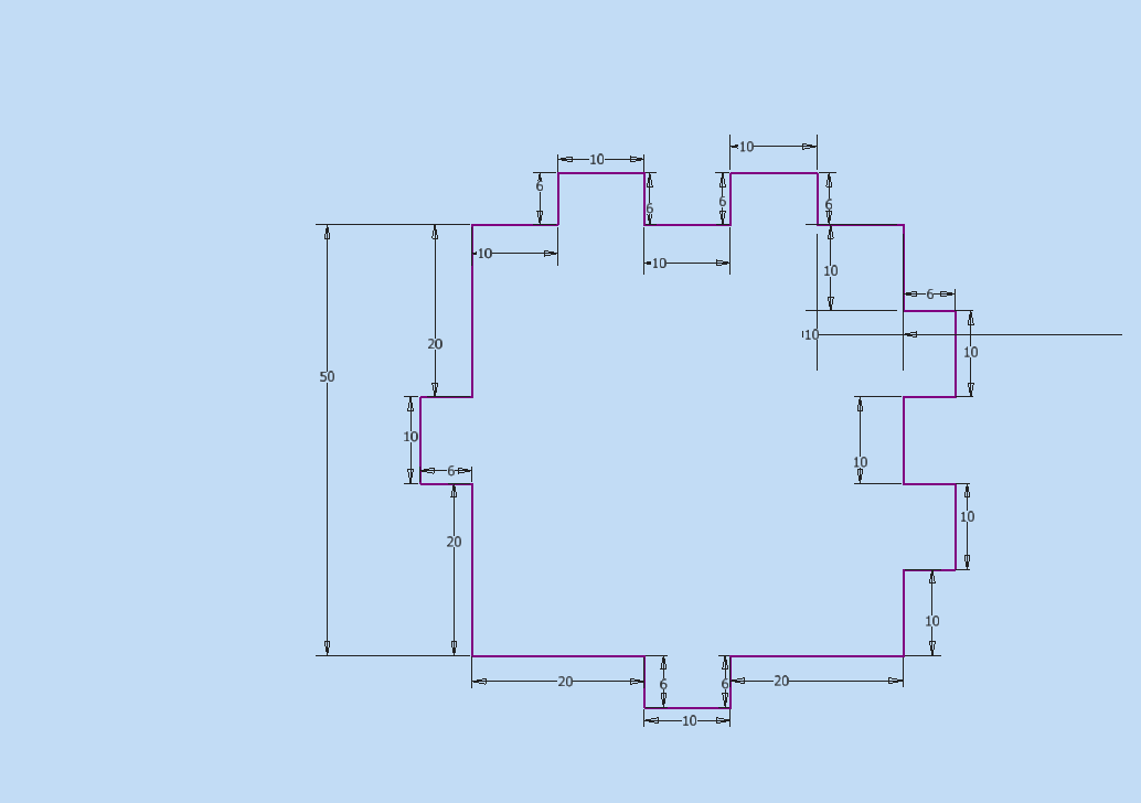
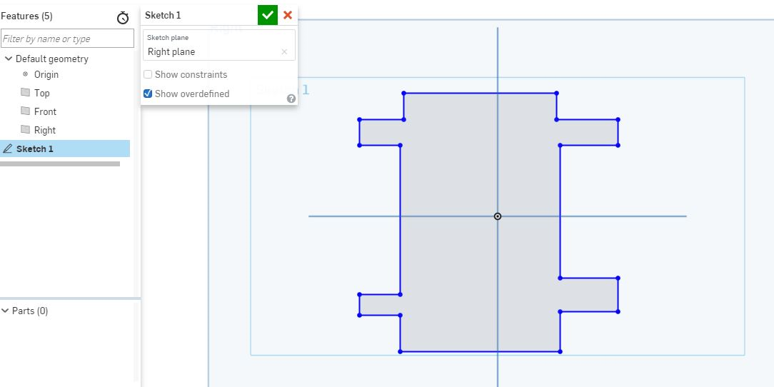
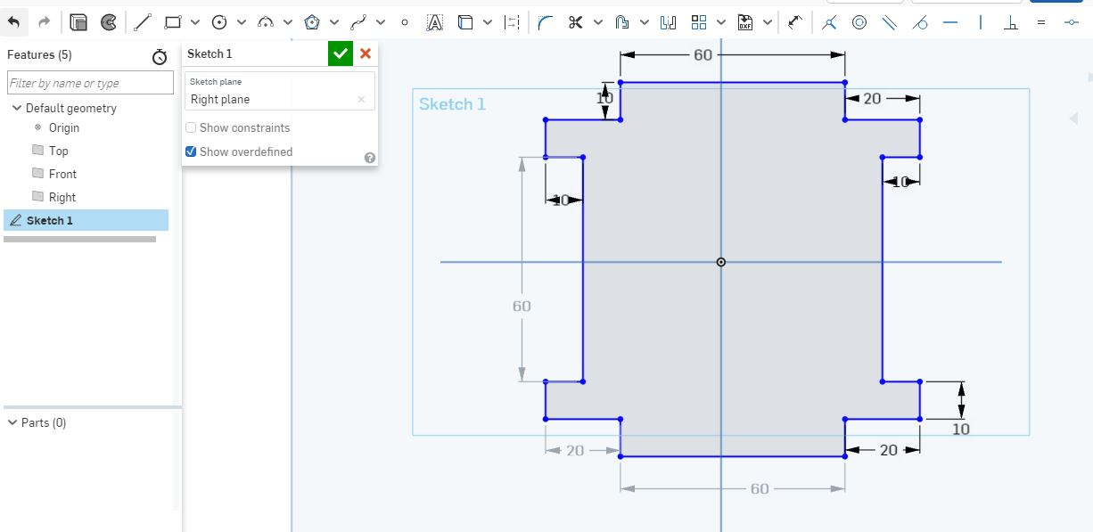
Did the same for the other sides remaing then I gave measurement. as shown.
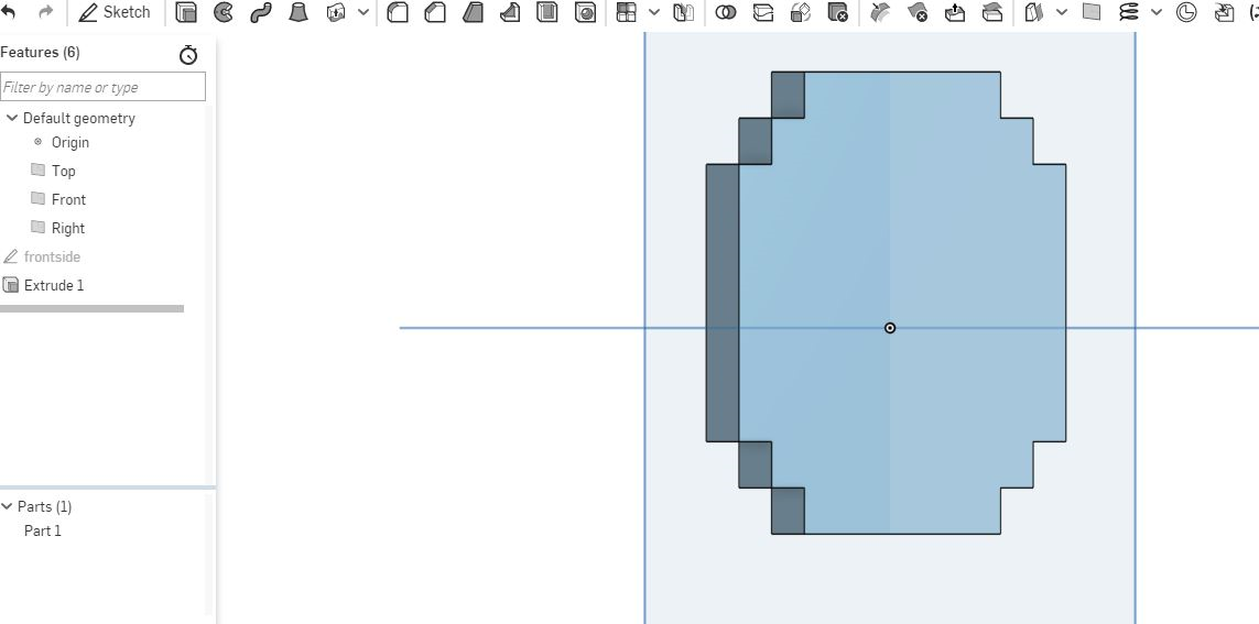
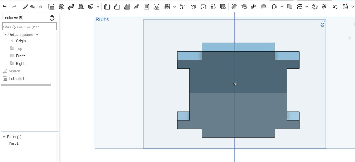
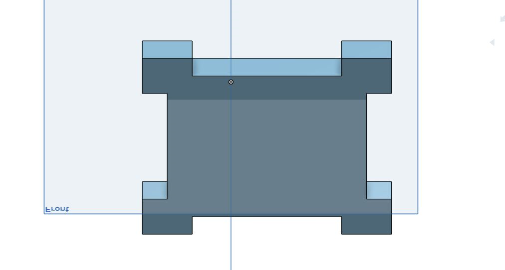
Finished the 2D sketch then gave it an extrusion to make it 3D as shown.
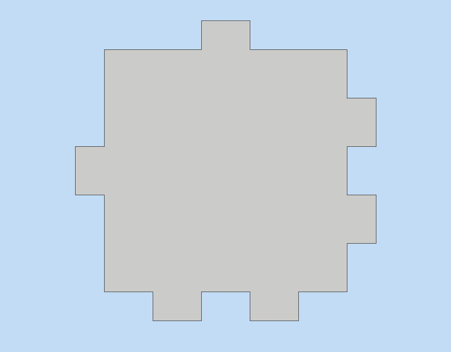
In this case the thickness I used was 6mm. even for the berspes material.
Full Spectrum Lasercutter Testing
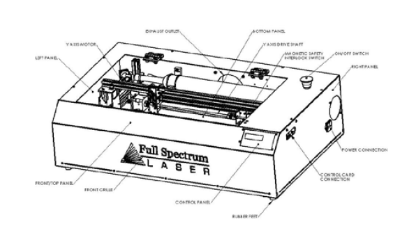
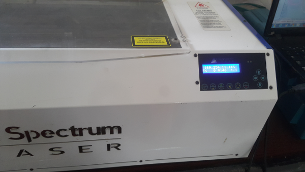
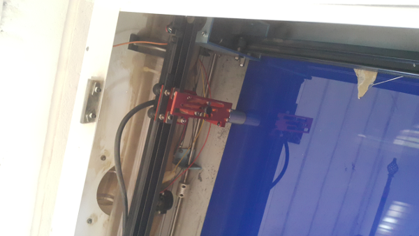
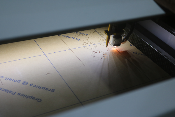
I used the named lasercutter as shown in the image below and since I had never interated with a lasrcutter before I downloaded its manual first which was a few pages and went throug it. learned how to power it and the key components involved like ventilation which has to be put outside in an open place. the water in water outlets fo running the water inside the tube inside the lasercutter.
I downloaded its drivers and software the Retina Engrave software.
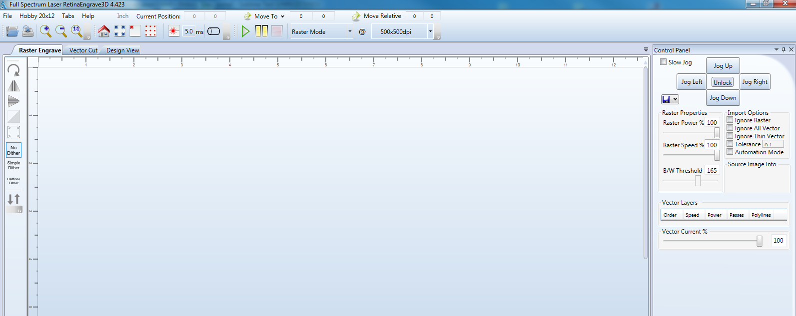
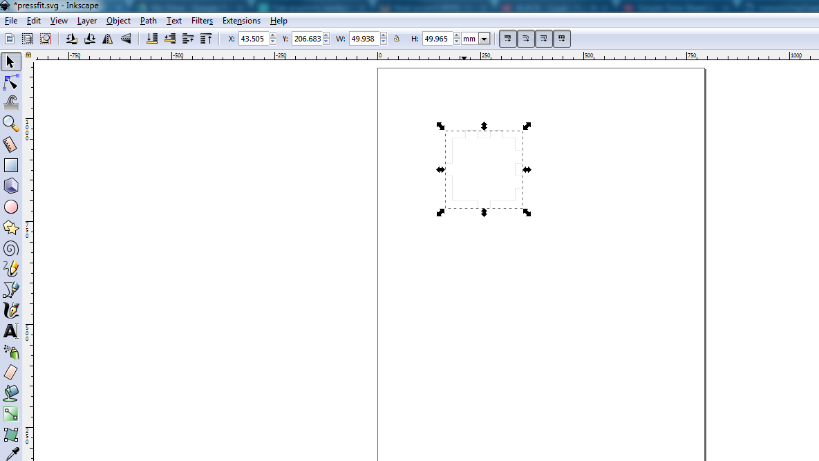
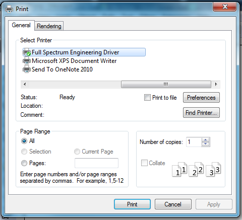
I used inkscape to import the designed svg image then printed it using the lasercutter.
Fist I had to set up the bed for the lasercutter with the acrylic material of 6mm thickness. I connect my laptop using the ethernet cable then opened the software.The buttons highlighted below are used to configure the lasercutter.
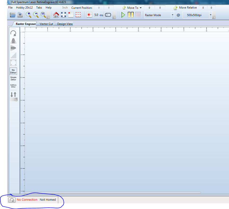
For the lasercutter to be able to connect I entered the ip adreess shown in the screen in my laptop still on the retina software.
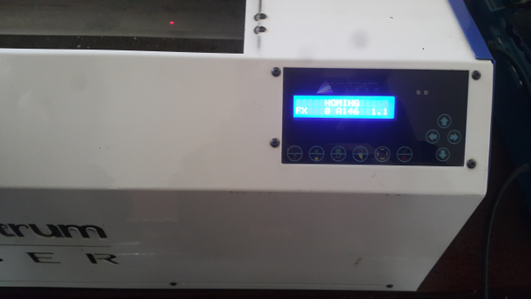
Then clicked the home button to home the lasertool to the correct position. when you wat to move it to a different position i used the arrow buttons on the screen of the lasercutter.
After it connected and homed the tool and the bed i put the acrylic. i printed the image form the inkscape.
This is how the design get displayed once you print it.
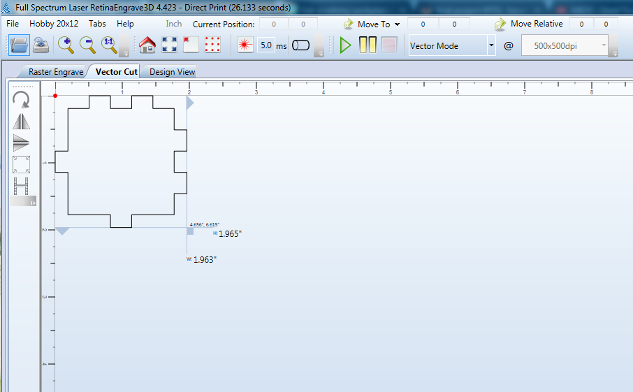
I used different speed and passes and power to see which one will cut through. i found that when i used a higher spped then I had to do many passes before it cuts through. I kept on vaying between the speed and power untill finally I got the optimum to cut through the acrylic. At fist the it wasnt cutting well soo I had to use a focussing tool to focus the lense.
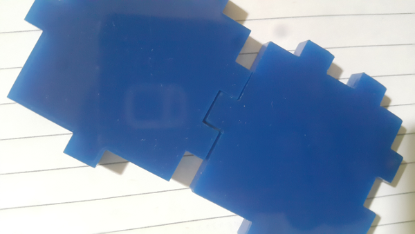
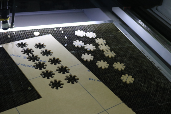
This are the diffrent cutting I made then finally it cut through. I also did a test with the fab text and see how it will be able to through the small variations.
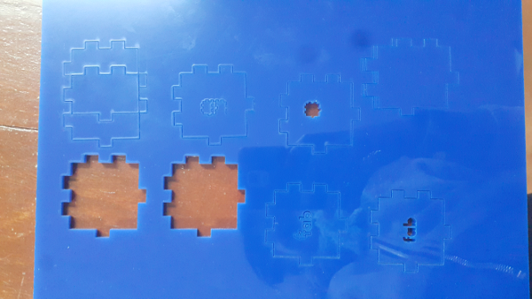
These are some of the parameters that I used in for the lasercutter. It took several trials before it could finally cut through.
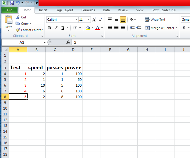
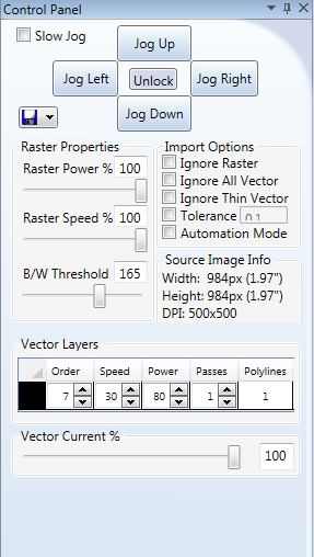
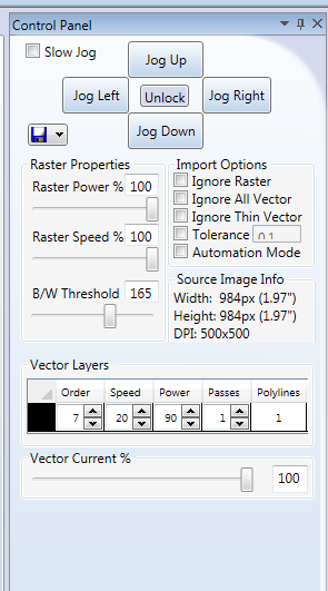
Used the control panel for the software to do vary the parameters.
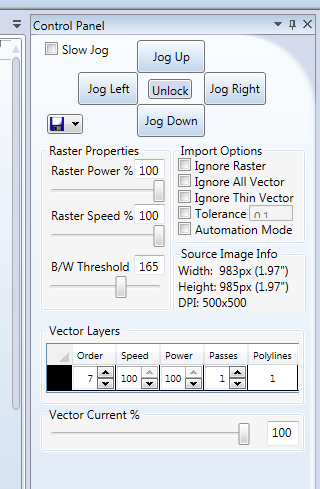
Some of the screen shots for the tests that is Test1, Test2 and Test3.
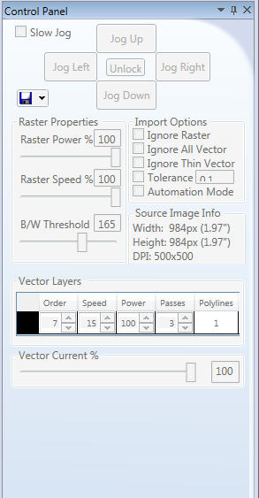
Then measured for the kerf difference I realised there was a difference of between 0.08mmm to 1mm.
Challenges
i). One of the challenges I had was trying to find the right speed, power and passes for the lasercutter to cut through the acrylic. It took me several test before I got the right speeds to cut through the 6mm thickness as shown in the above documentation.
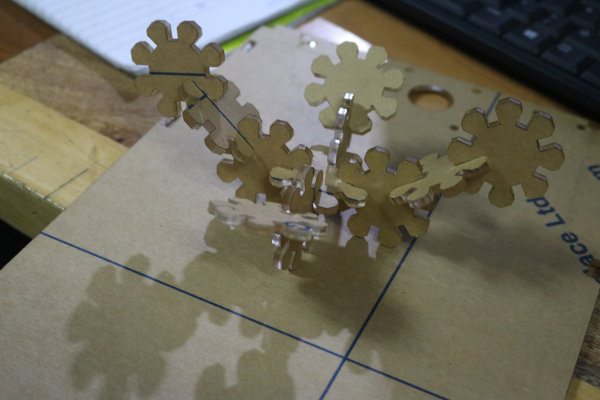
Pressfit
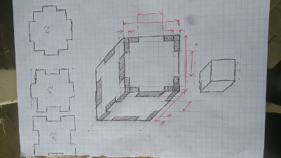
The first step I drew the pressfit in a paper. I did a simple cubic pressfit. This was interesting for me since it was my first time doing a pressfit.
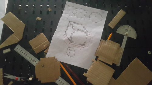
This is my workspace.
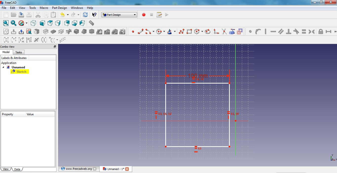
Started with the freecad for the simple 2d design and measurements. I just wanted to see how I will go about it.
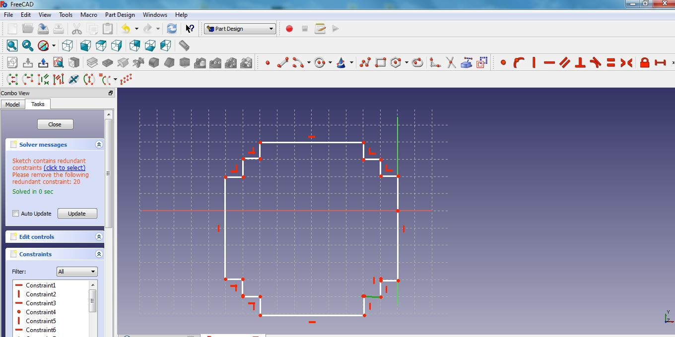
The cubic has three side planes i.e. top, bottom and the side.
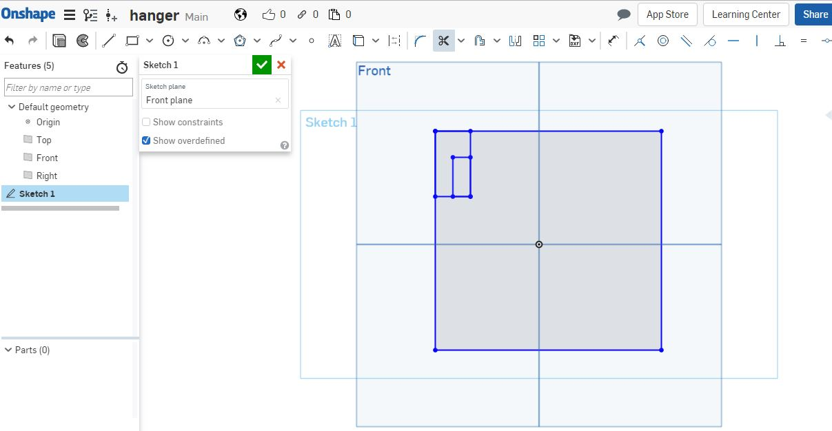
Frontside
With the frontside I begun by drawing a large rectangle then drew small rectangles inside the main rectangle.
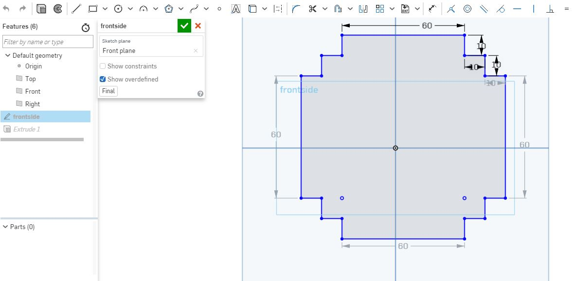
Then cut out the extra lines using the cutting tool. the measurements for the cubic is 100mm by 100mm. I had to acount for the cutouts as shown and gave them measurents.
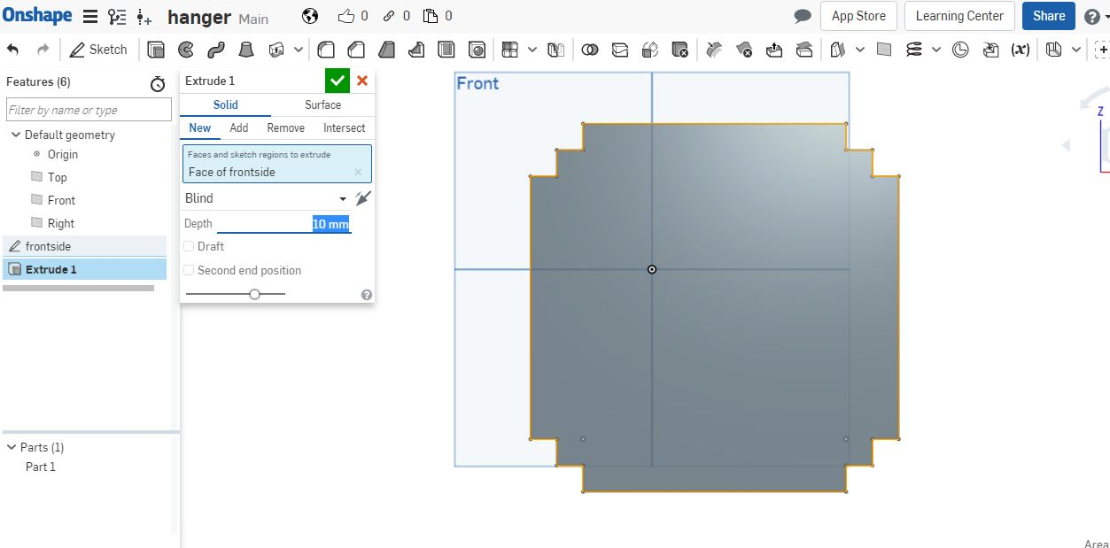
Gave it an extrusion of 10mm that will be the size of the thickness and also the insertion points.
Sides
I used the same process like he front side, started with rectangles as shown.
Cut out the extra lines then gave it measurements.
gave it an extrusion of 10mm same as frontside.
Top side
Followed similar process.
Gave it an extrusion of 10mm same as others.
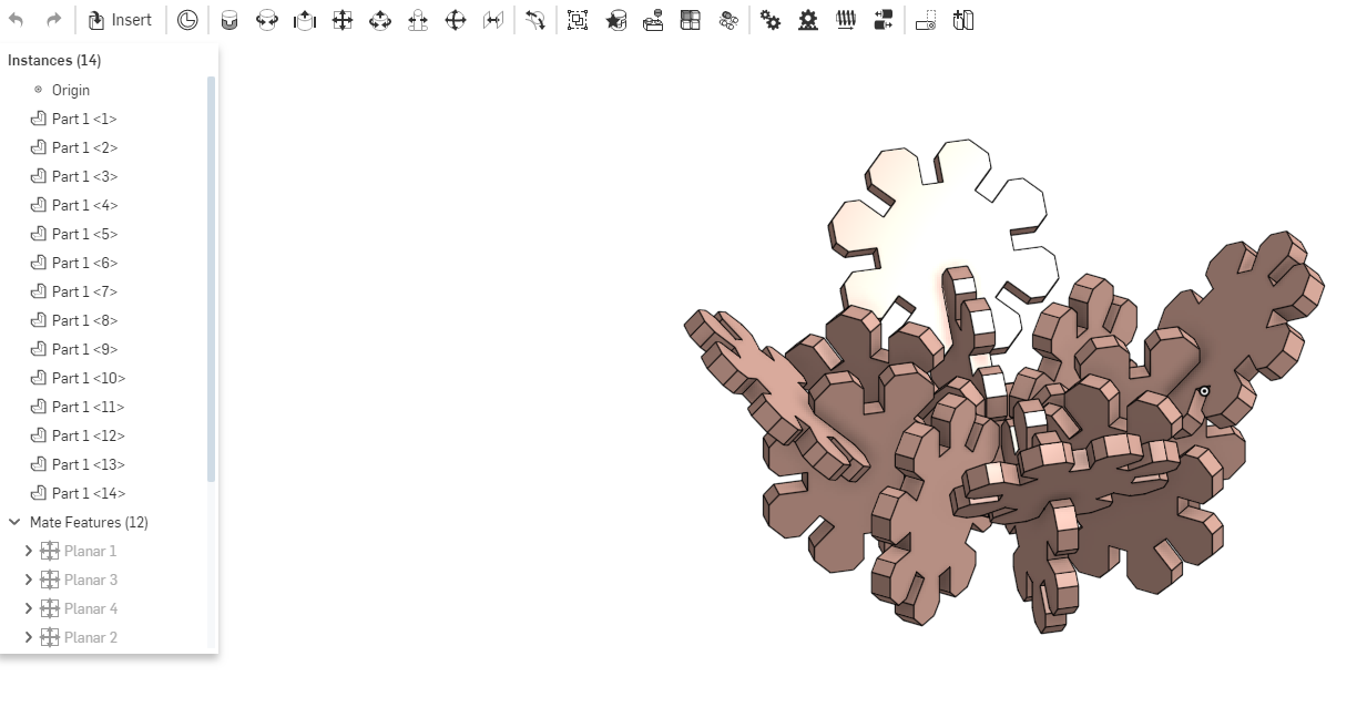
Assembly process
Since I did the whole of the design using onshape software. I decide to do an assembly for the pressfit...Me being a newbie this was really fun.
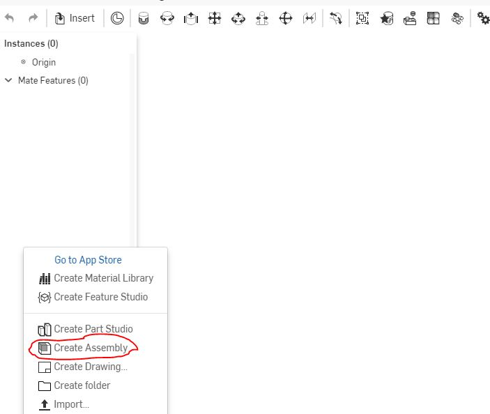
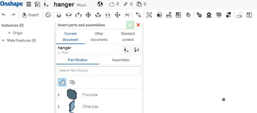
Started by creating a new assembly place as shown.
Then imported the studio parts I had made earlier.
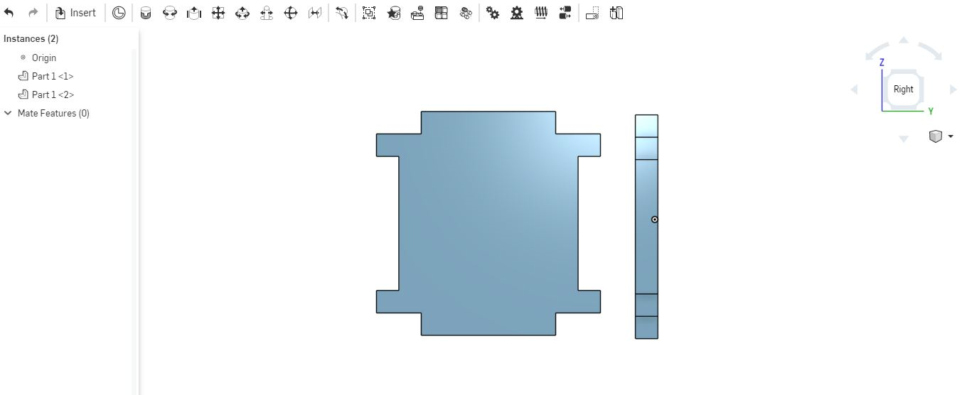
To assemble the parts I used the planar mate tool as shown in the video below.First you select one point from one of the plane then select another point form the other point. while selecting you have to ensure that the two points can be joined based on your design.
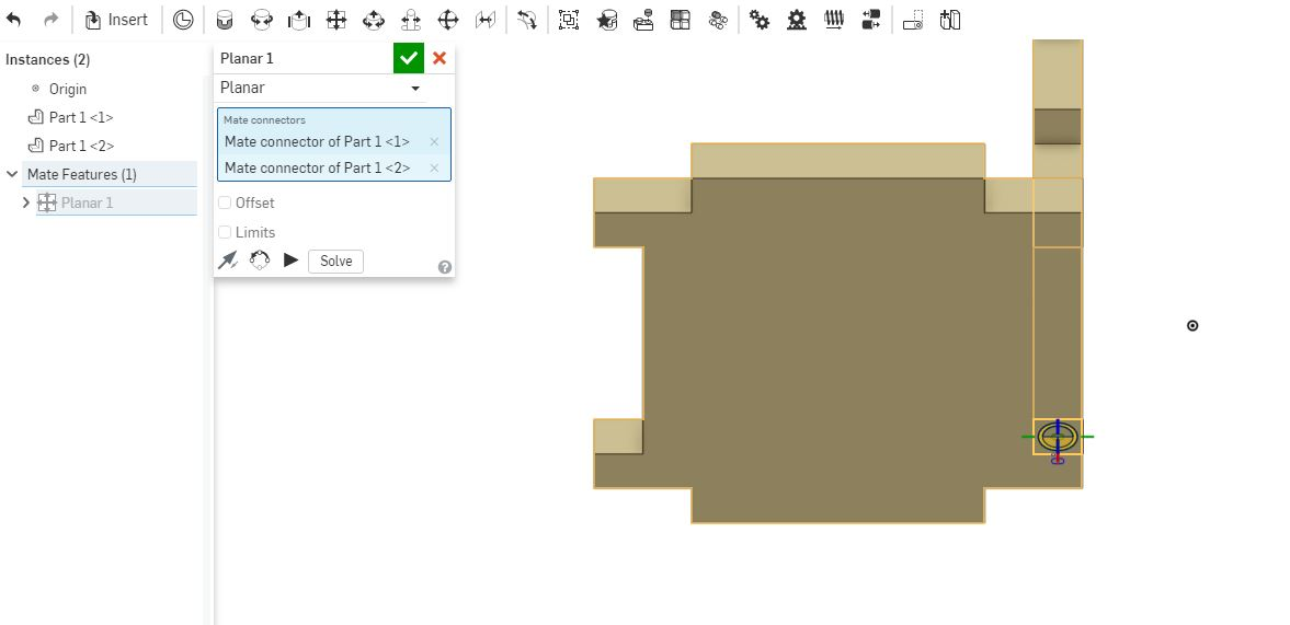
Half way done assembly.
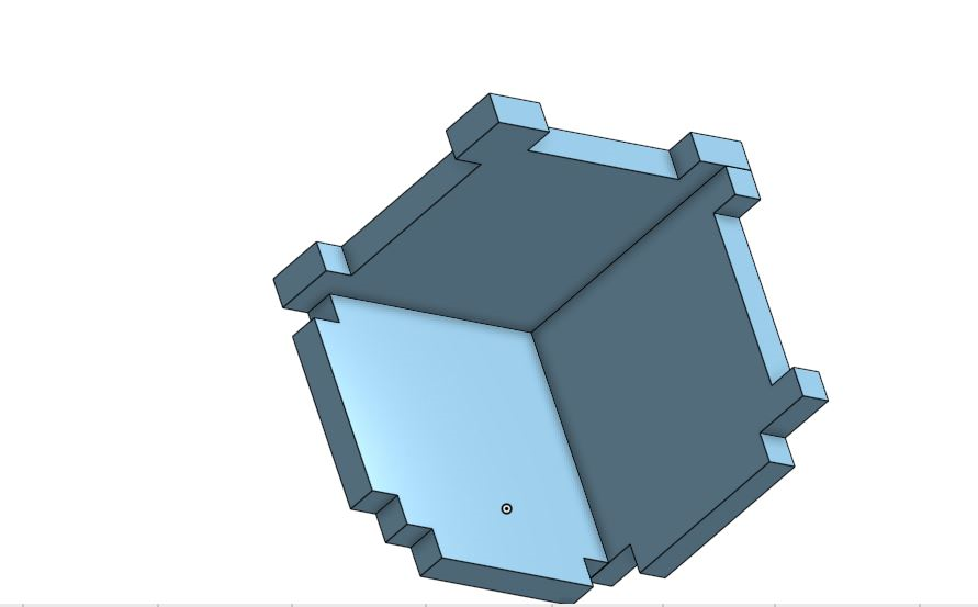
Complete assembly with video.
Re-doing the Pressfit
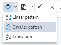
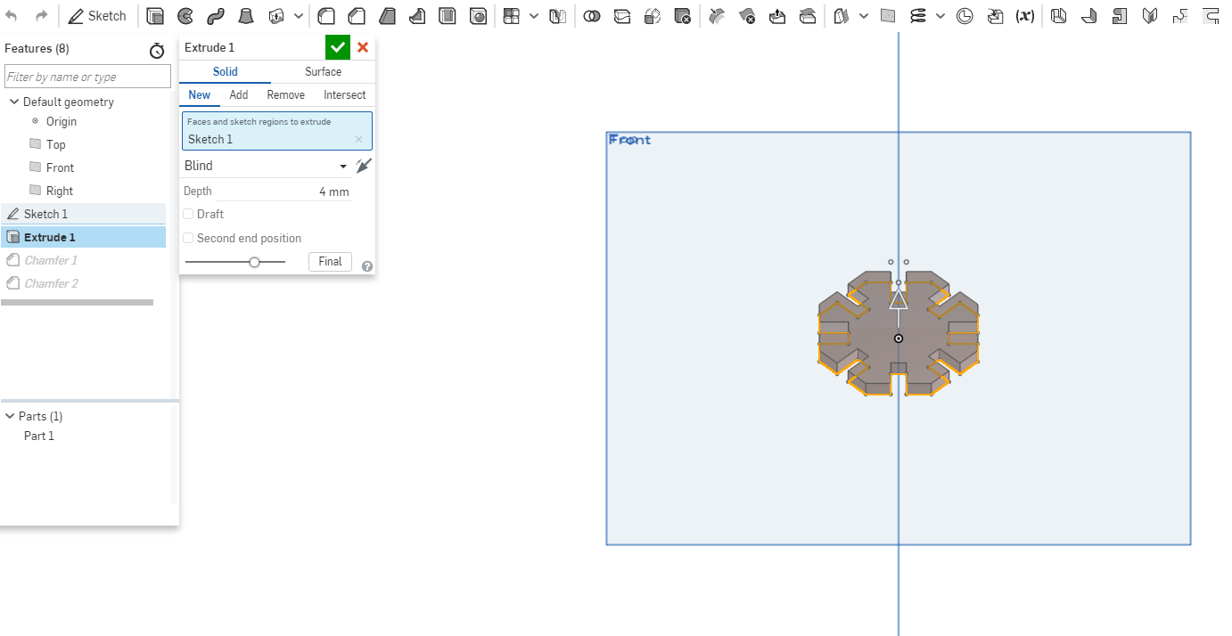
I redid the pressfit using onshape, started with a sketch then I drew a polygon shaped using the polygon tool as shown and then added the number of sides. To make the insertions I used the line tool to make a rectangular shape at the middle line between the corners. Using the circular pattern tool I recopied the rectangular shape design all around the hexagon to make it uniform throughout the design.
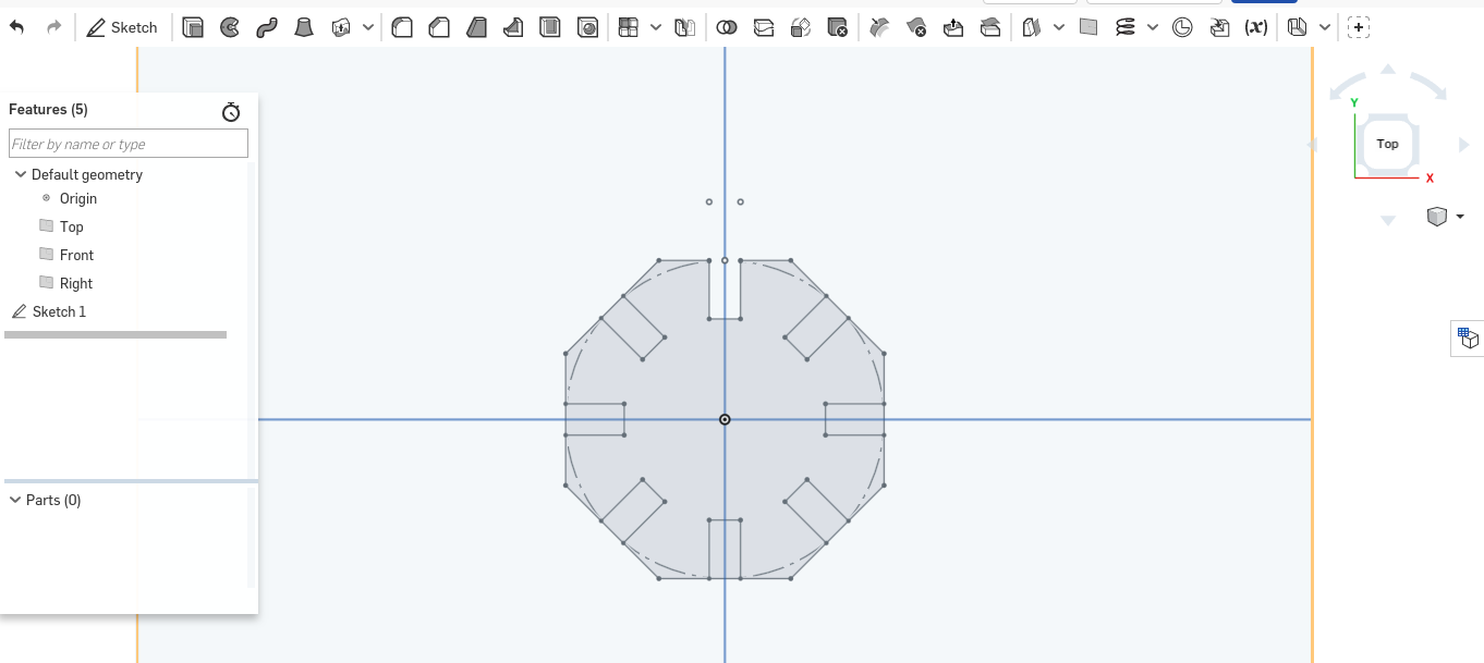
Using the equal tool to make all the lines equal to each other by using this tool it makes the lines parametric to each other hence when one changes the other(s) changes too.I gave one of the line a measurement of 4mm and used the equal tool to make them equal to each other.
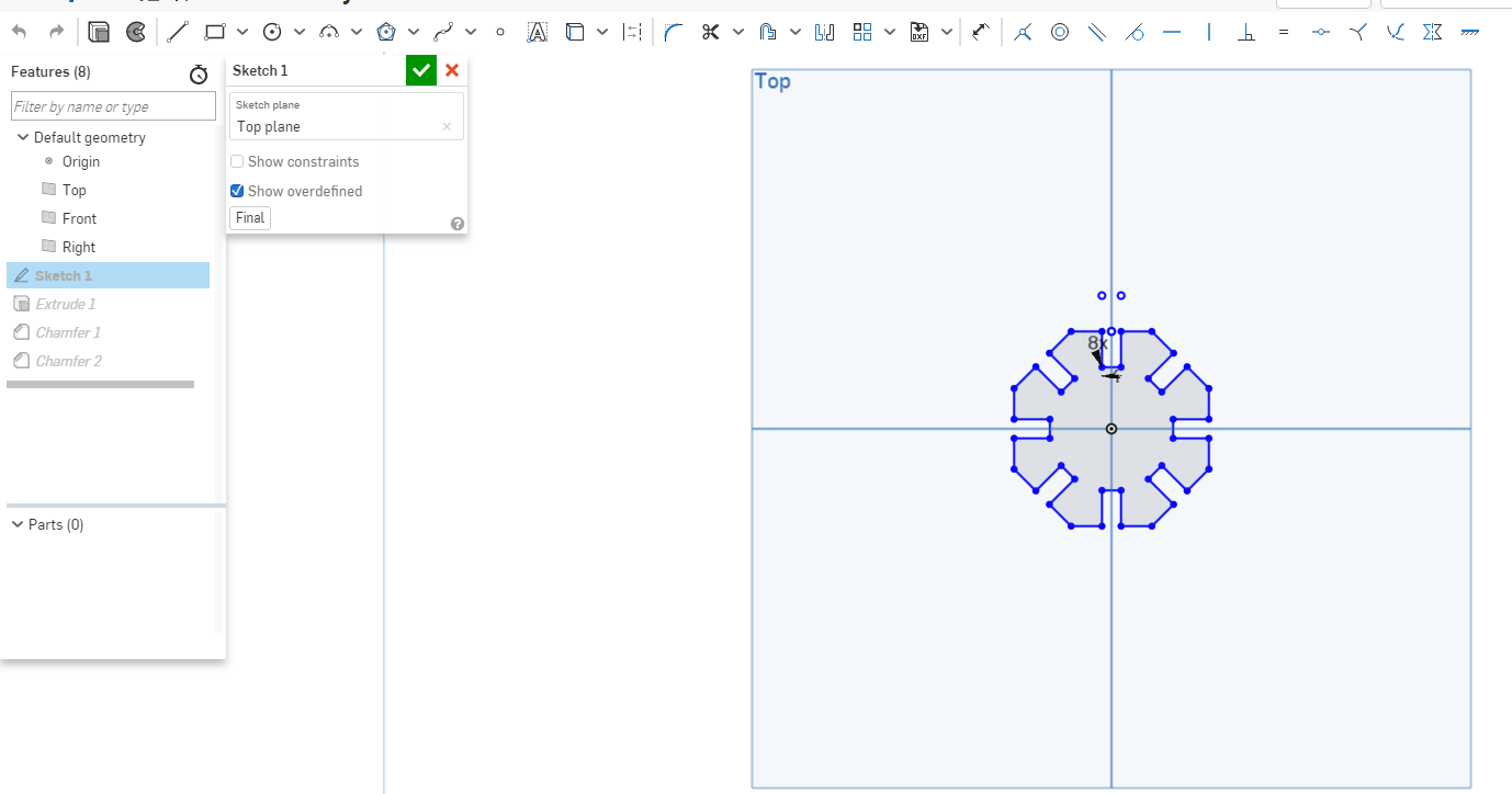
Then I extuded it to 4mm.
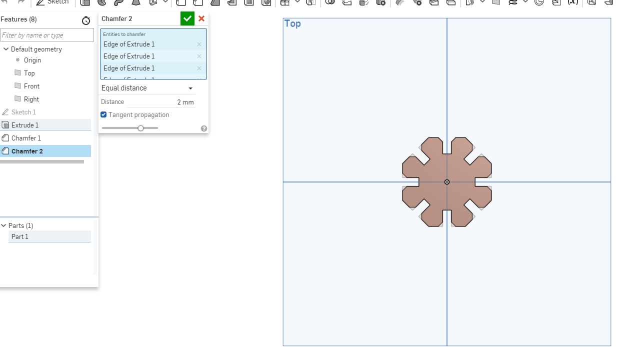
To make the pressfit fit in with bliss I used the chamfer tool to create a bend corner.I gave it a 2mm chamfer.
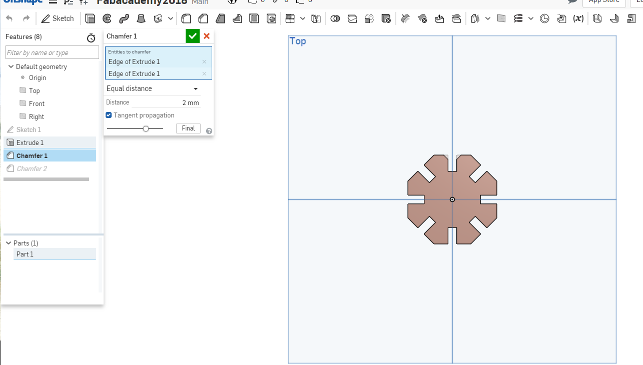
Then I did the same for the rest.
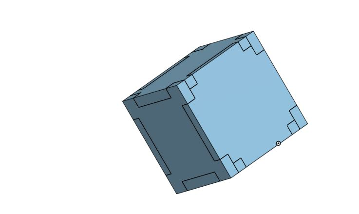
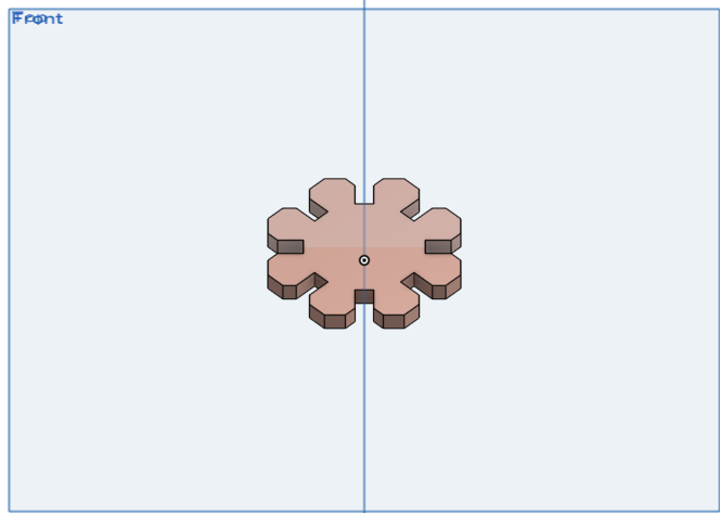
The final image of the pressfit.
Assembly
For the assembly I used the create assembly as shown.
Then used the insert button to select the shapes and drag them to the newly created assembly. The palnar mate tool connects the different planes together to form a join them as shown.
Parametric short video
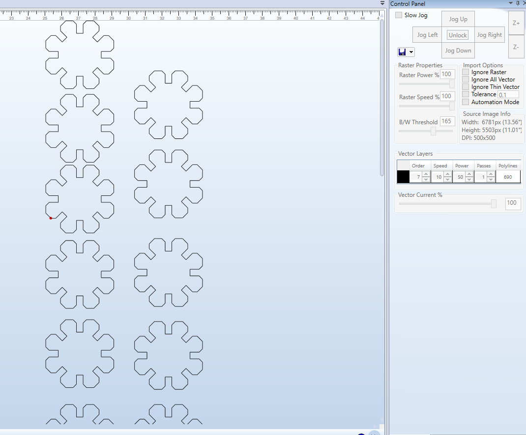
lasercutter practicals
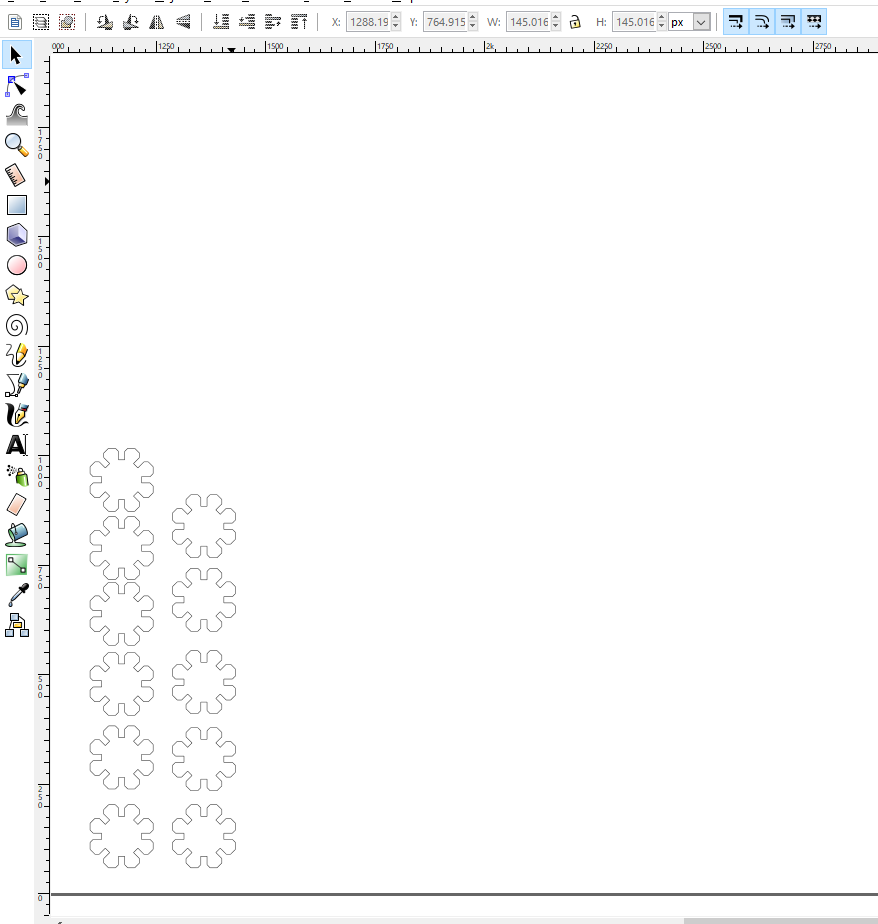
I imported the pressfit design in the inkscape software then made a few copies of the design and loaded it to the engrave software for the lasercutter. I made sure the lasercutter is homed and set the correct settings for cutting that is the speed, power and passes as shown. I used the acrylic material of 4mm thickness.
I run the lasercutter ensuring everyhing is working properly the connections for the lasercutter.
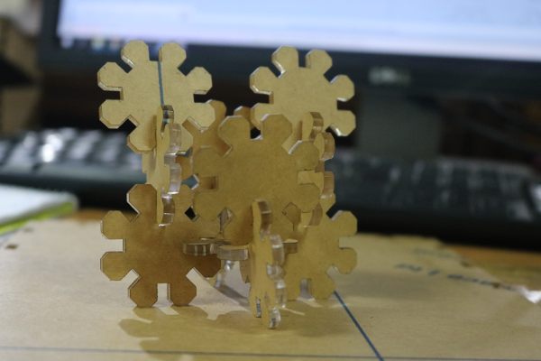
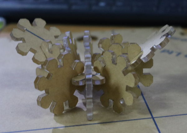
Assembling the pressfit
Now to the fun bit, I assembled it in several ways as shown.
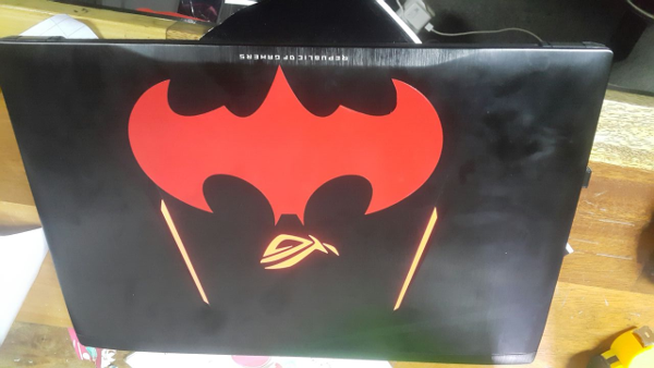
Vinylcutter design
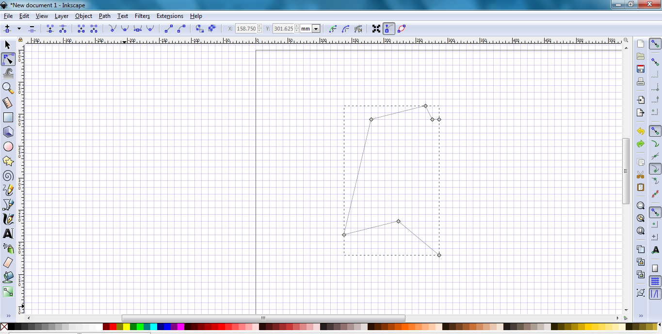
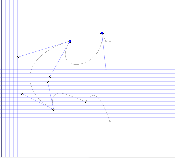
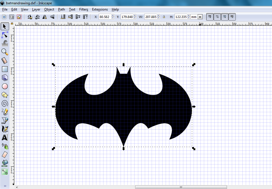
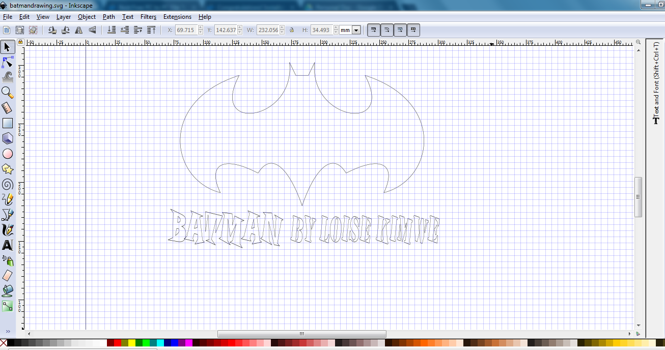
I did a different design this time around inspired by the Batman character. I have always been a fun of the superhero soo I did the logo version of batman using Inkscape. I used a picture online to refernce the design. The line and curve tool  came in handy where I did a staright lines first as shown.
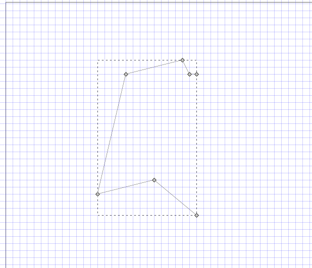
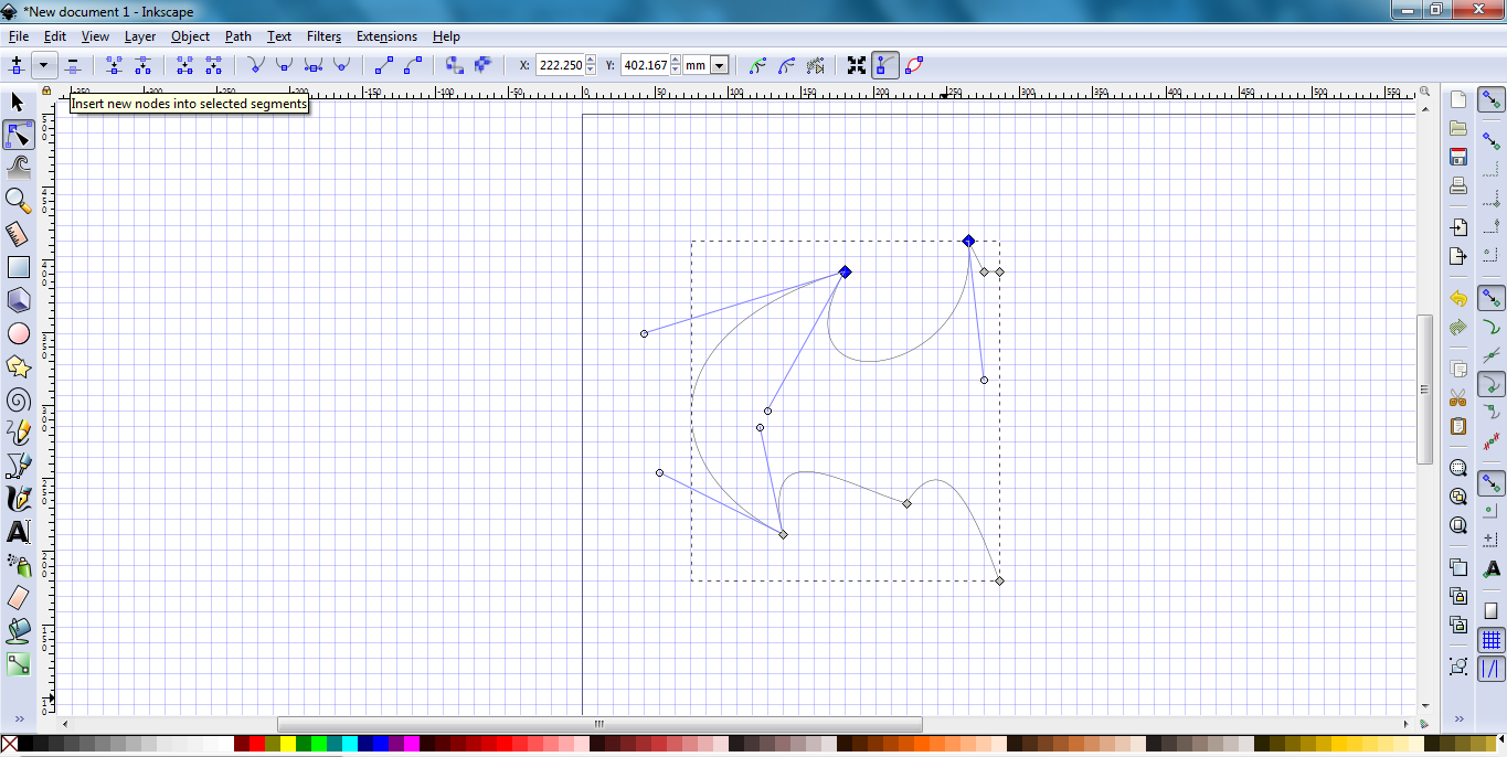
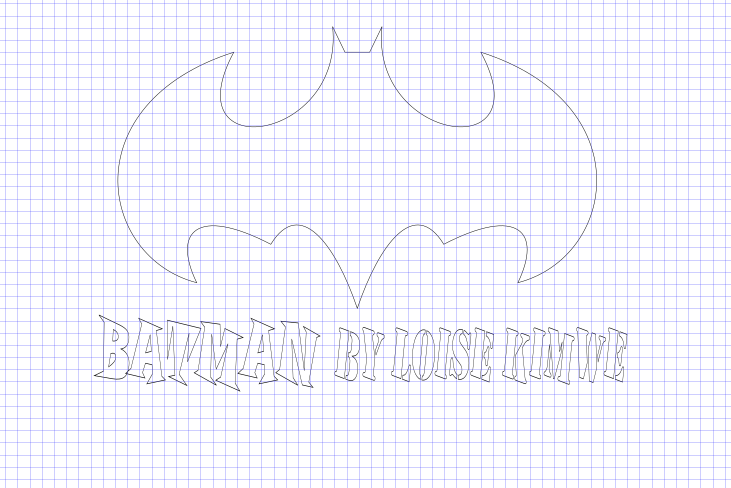
Used the curve tool to curve the lines in shape as shown.  I utilized even the points to ensure the design resembles the batman logo.
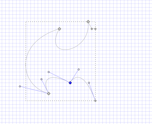
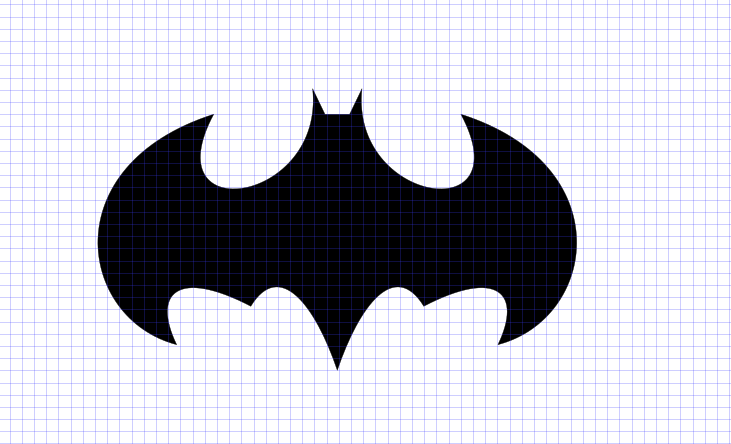
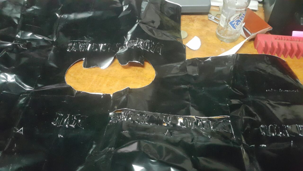
Once done I copied the design then copied it there, using the mirror tool to mirror it to face the other part.
Used the curve tool to curve the lines in shape as shown. 
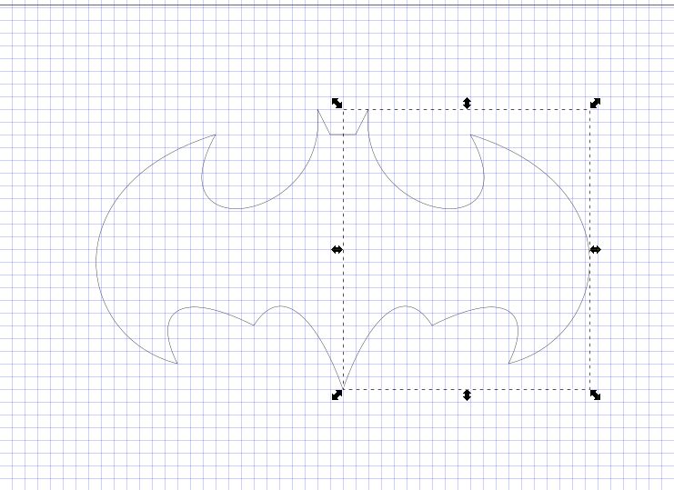
Since they are two different part I used the joining tool to join them to become one part of the design by selecting the intersecting part between the two.
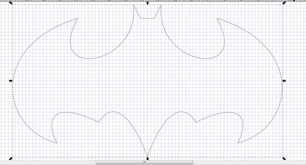
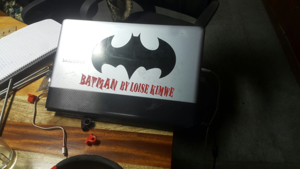
I gave it some color as shown and some text.

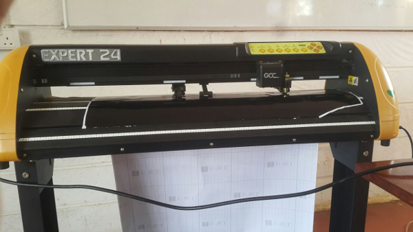
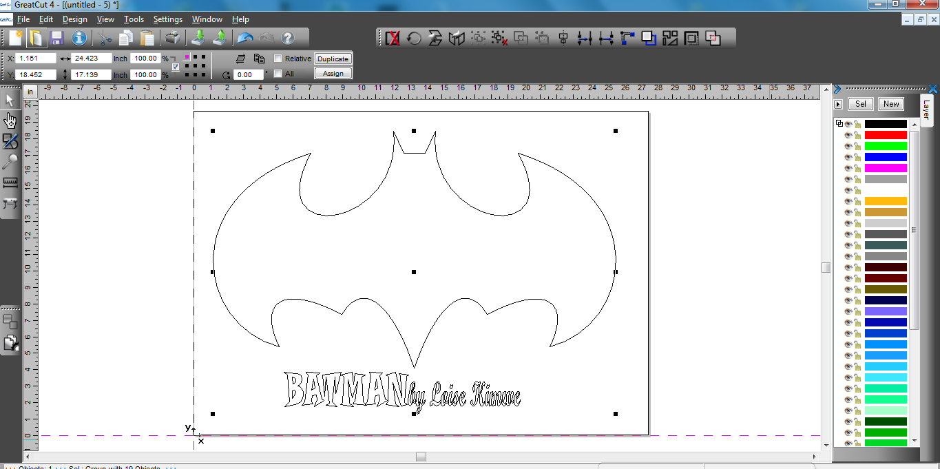
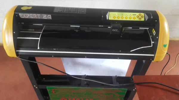
I downloaded the GreatCut software that is used by the vinyl cutter and installed its drivers as an svg file which I had exported from the Inkscape software. The vinyl cutter that am using is an Expert 24, I used the usb cable for connection.
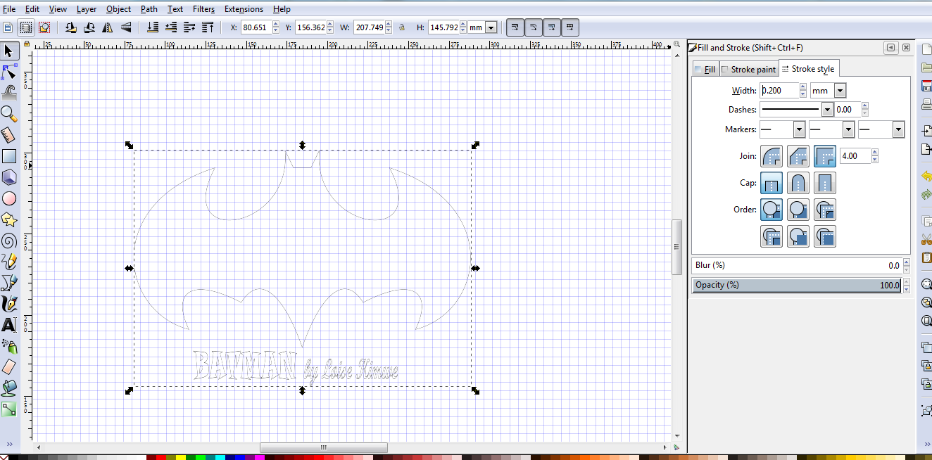
I imported it to greatcut software as an svg file. For the vinyl cutter to cut. I learnt that the vinyl can not be able to cut it as it since I had not given it an outline so I went back to the design and removed the fill then added the stroke style of 0.2mm as shown.
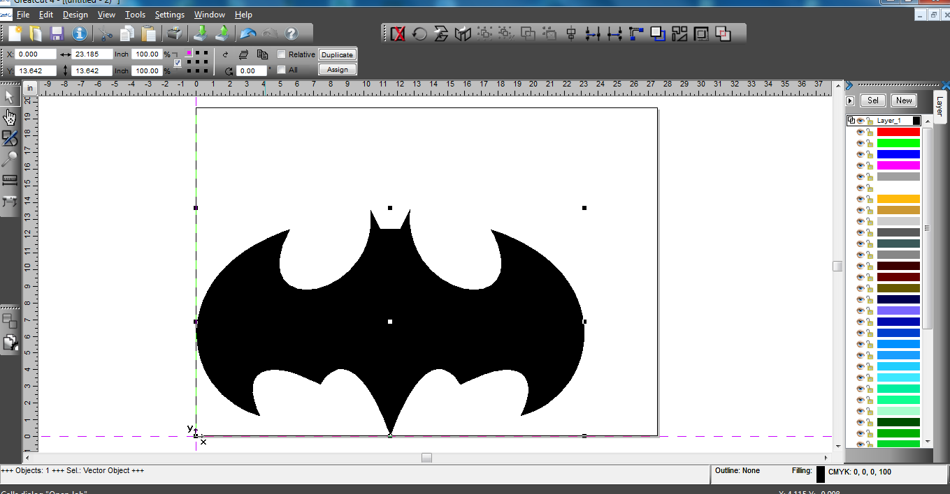
I imported it back to the Greatcut software
Cuttig out the design
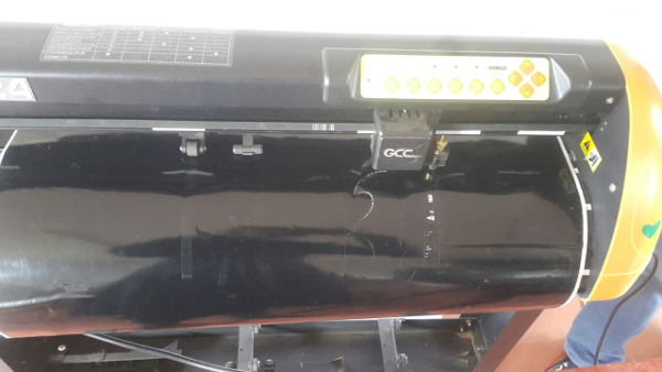
I laid out the vinyl for cutting and homed the machine using the buttons shown.Then I send the design to the vinylcutter to print.
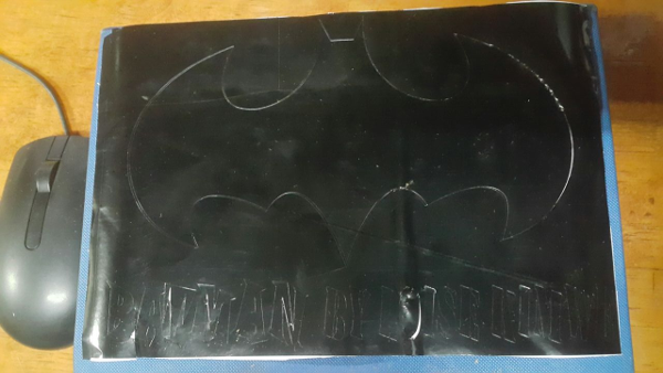
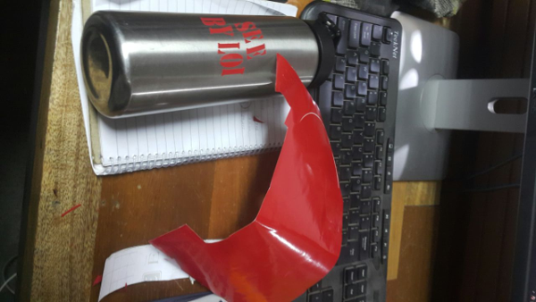
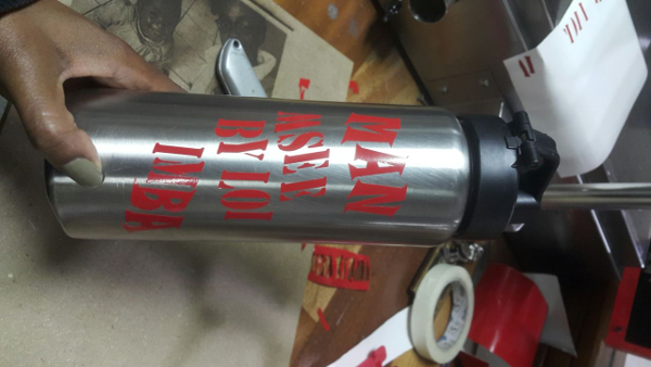
The final results.
Challenges
I did different cuttings varying in cutting strength settings until I got the correct settings for the design.