Week 4
Electronics production
Assignment
Group
• characterize the specifications of your PCB production process
Individual• make an in-circuit programmer by milling the PCB, then optionally trying other processes ATtiny45, ATtiny44.
In Circuit Programmer
In-system programming (ISP), also called in-circuit serial programming (ICSP), is the ability of some programmable logic devices, microcontrollers, and other embedded devices to be programmed while installed in a complete system, rather than requiring the chip to be programmed prior to installing it into the system.
Reference: Wikipedia
fabIsp
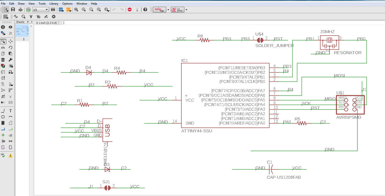
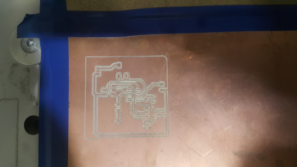
For this assignment I had to go through several tutorials on isp. I made the board using eagle I followed the below fabisp.
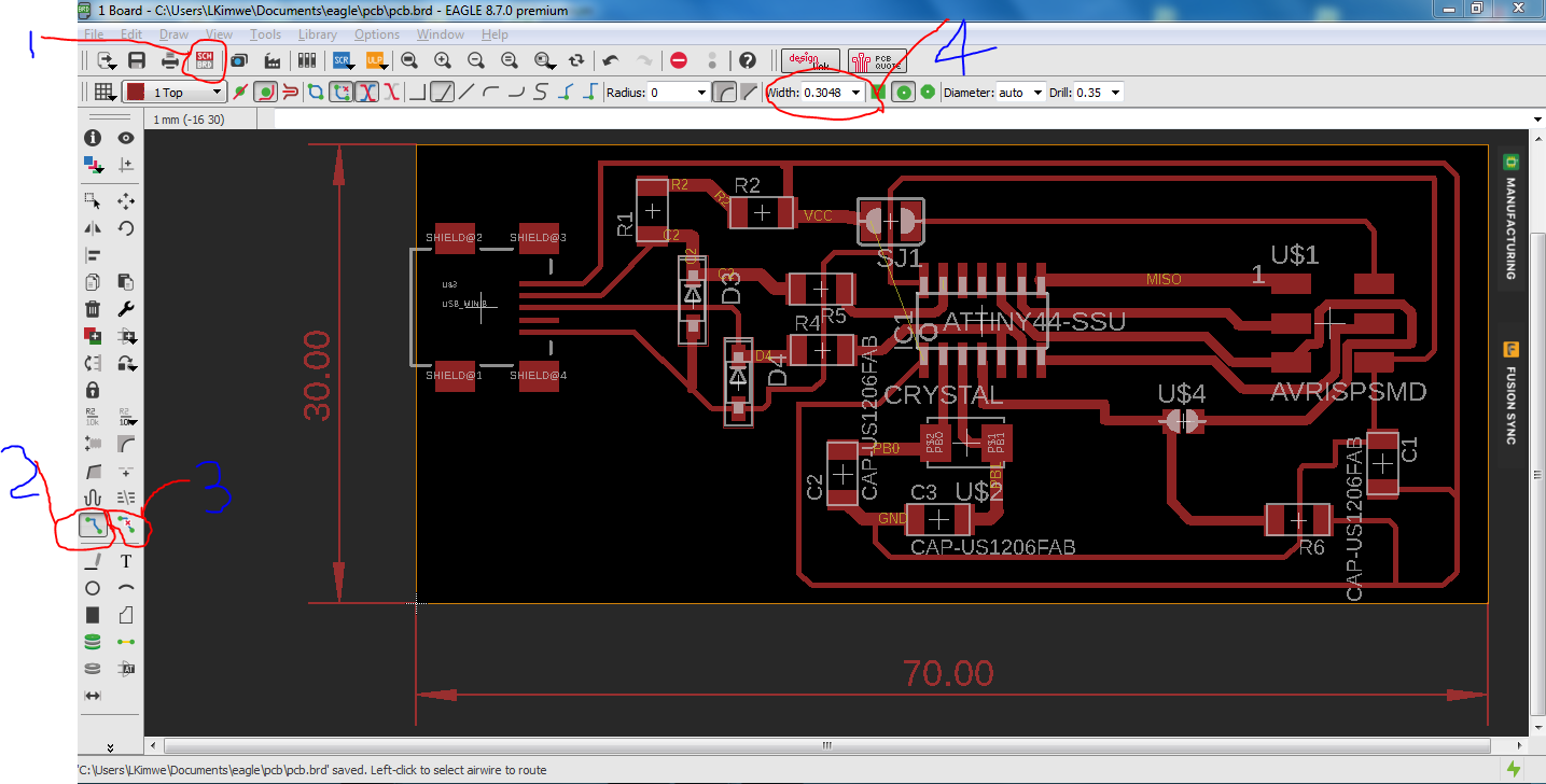
I designed it using eagle as shown below. the components were imported from the fab library. I struggled with the connections at first and labelling them. For this I used ATtiny44.
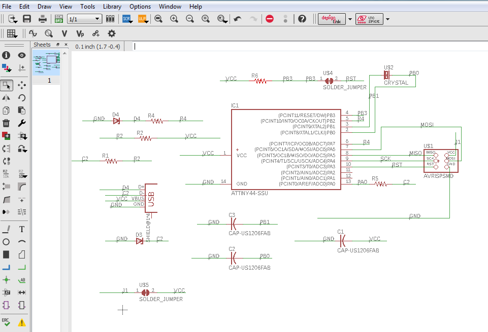
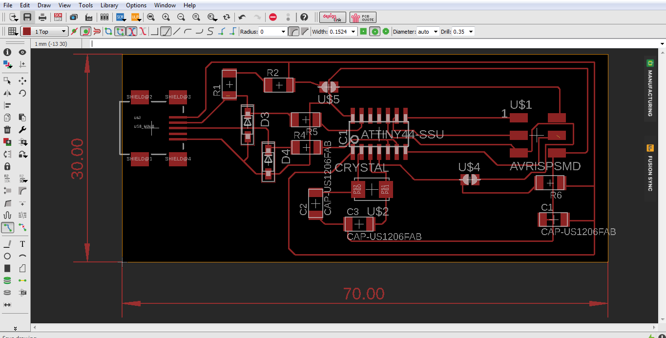
I used the 70 by 30 mm measurement dimension for the PCB. Rearranged the compnents on those dimentions to fit the exact measurements. I had a bit of challenge with arranging the components and their connections soo I went back and forth between the schematic board and the screen board.
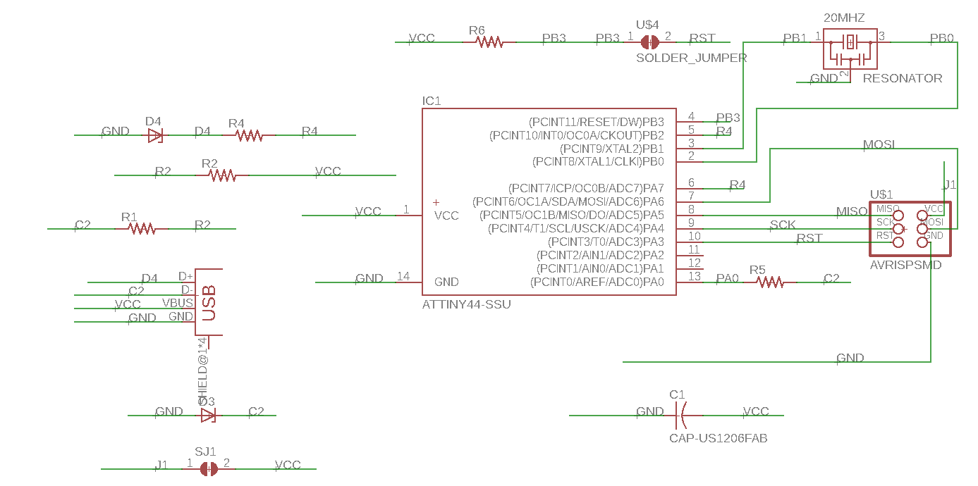
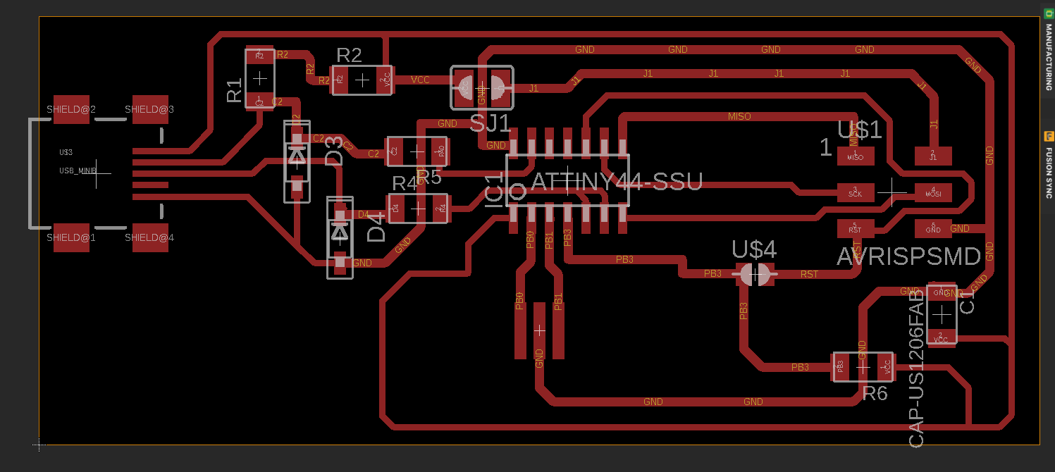
Redesigning the fabisp
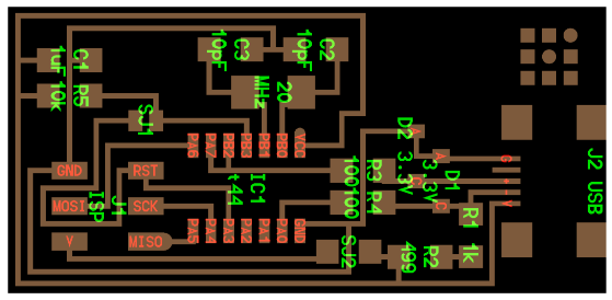
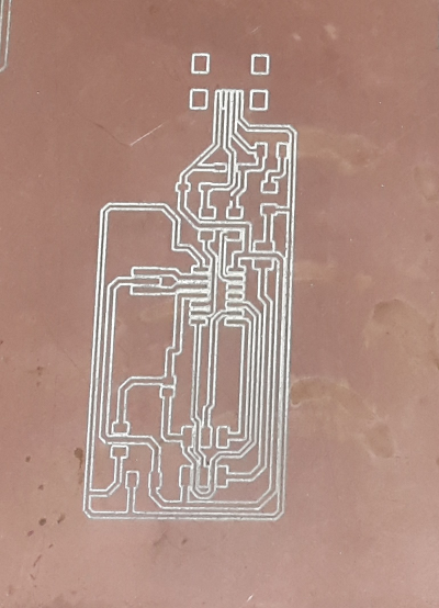
I redesigned the board beacuse I had a resonator and not the crystal so from the design I removed the crystal and the capacitors, replaced them with the resonator. Used the board below for referencing.
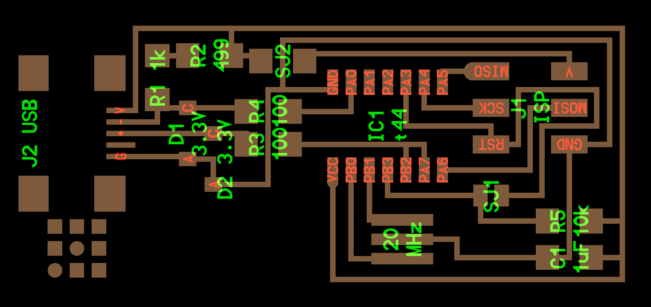
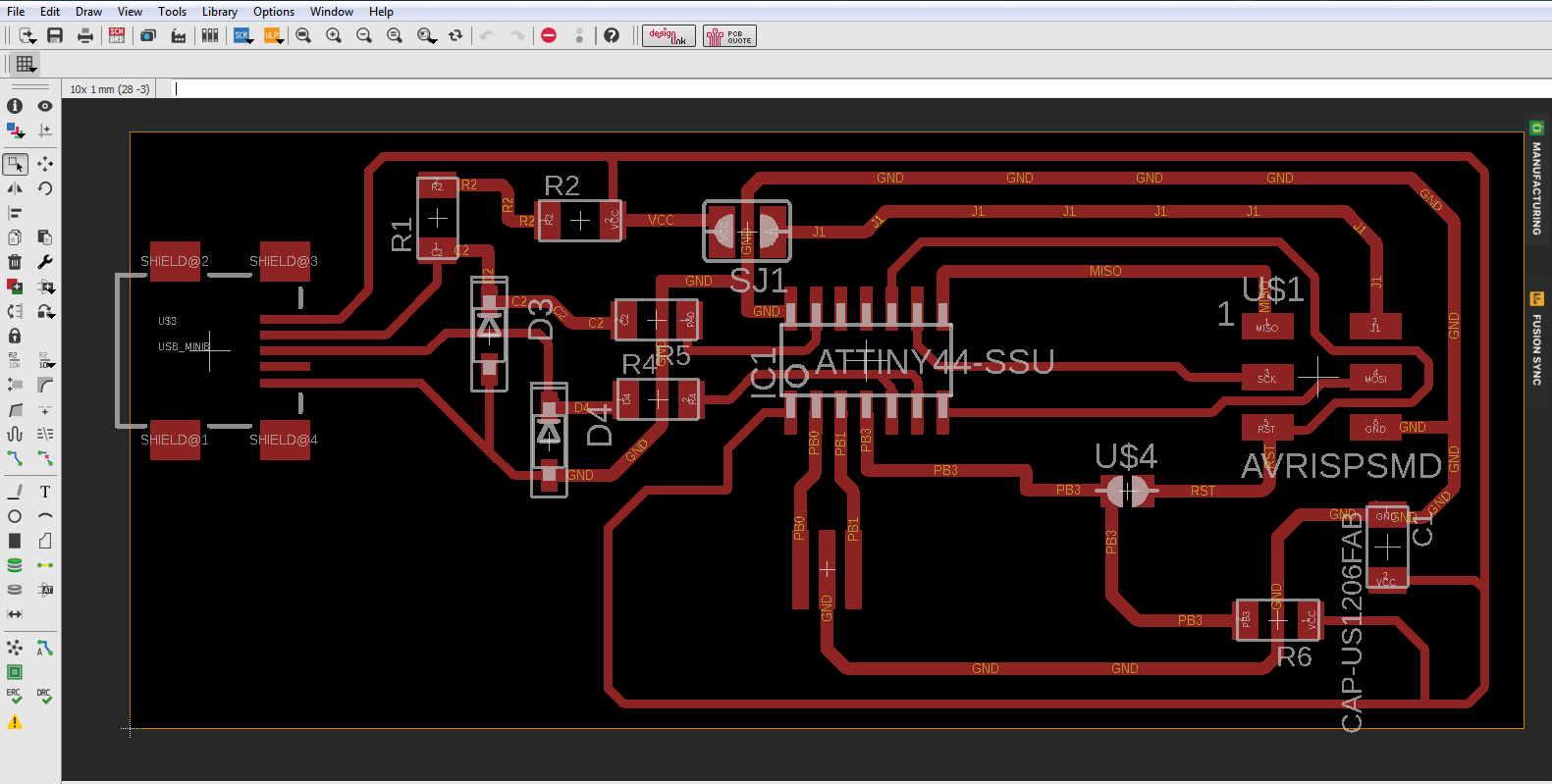
The final board design
Challenges
AT first I struggled with undestanding of the circuit and the connections involved between the diferent components.
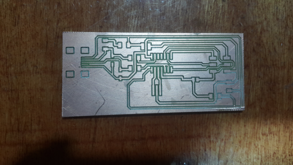
The tracks of the lines for connection I had used a thinner width then later changed it to a much sizeable thickness soo that I can be able to mill the board.
Before
After
Milling Process
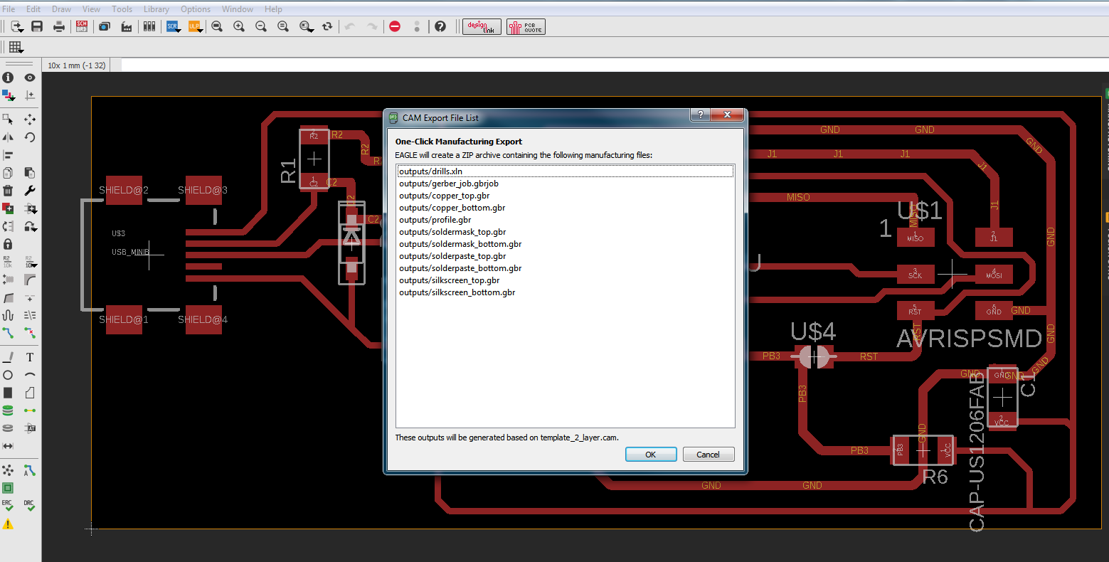
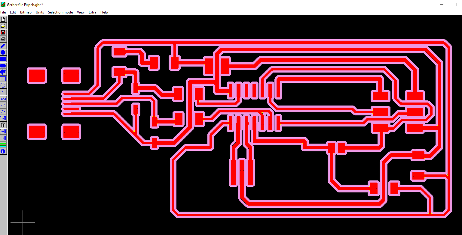
On Eagle software I generated the CAM data using the file dropdown menu. It generates several files for you as shown.
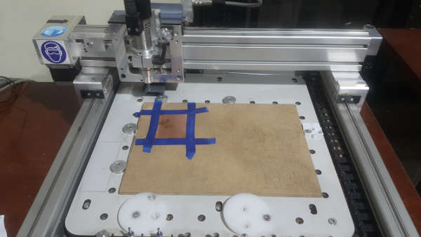
Set up the bed for the milling machine first and the boardt that I was going to mill as shown. This was for testing first.
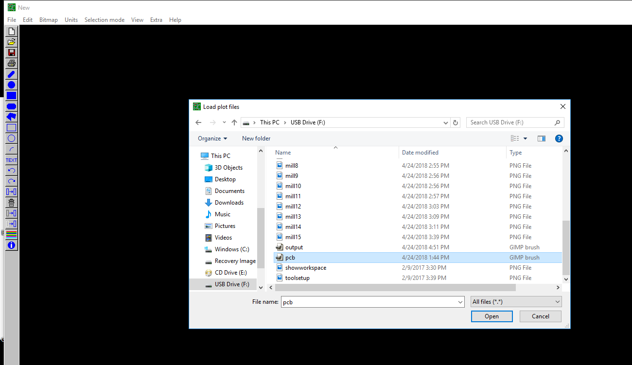
I used the IsoCam software to load the garber file for the pcb I jsut selected th egarber file I had generated from eagle, in this case i used the top garber file only. Clicked open then okay to load it.
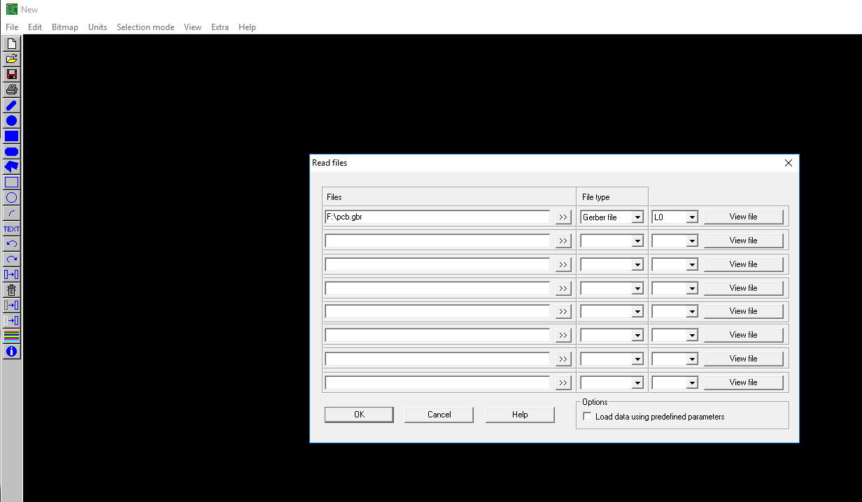
After loading the file, went to file menu option then selected create milling data that prompted a window as shown. Clicked okay to generate the millling data.
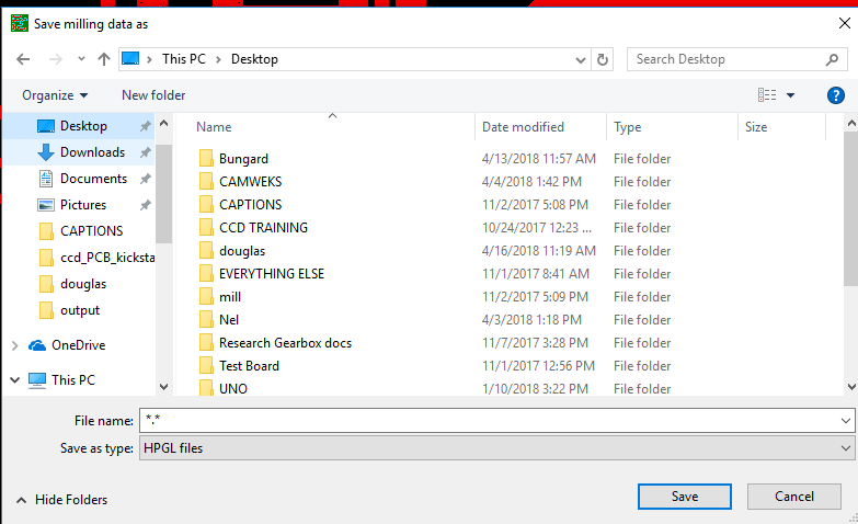
Under the file submenu option I selected save the milling data and saved it.
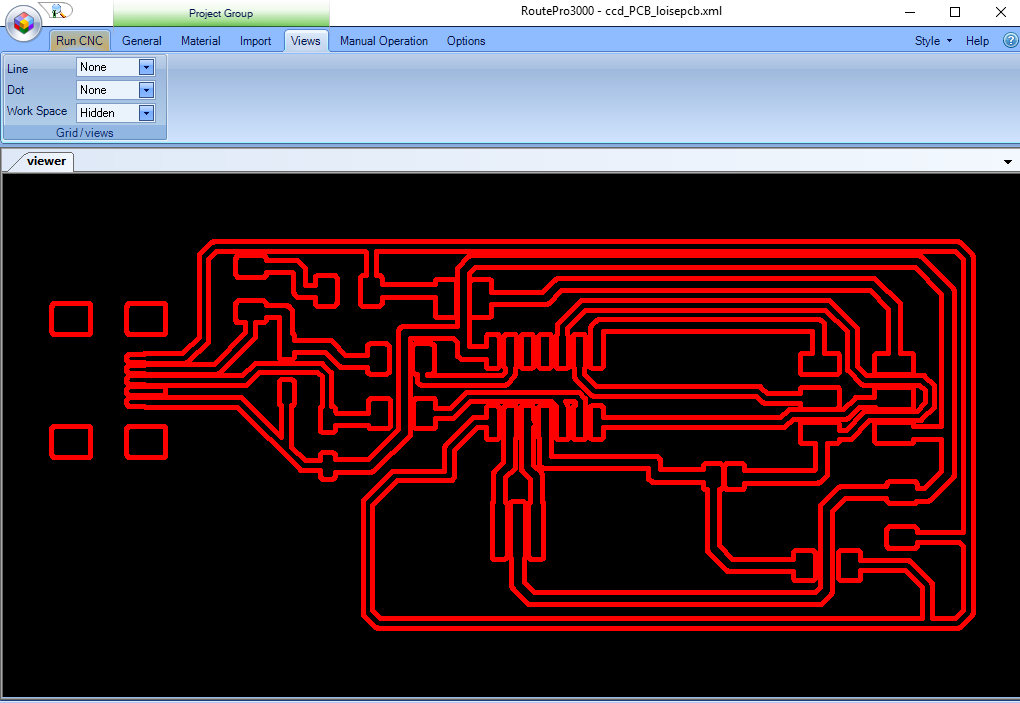
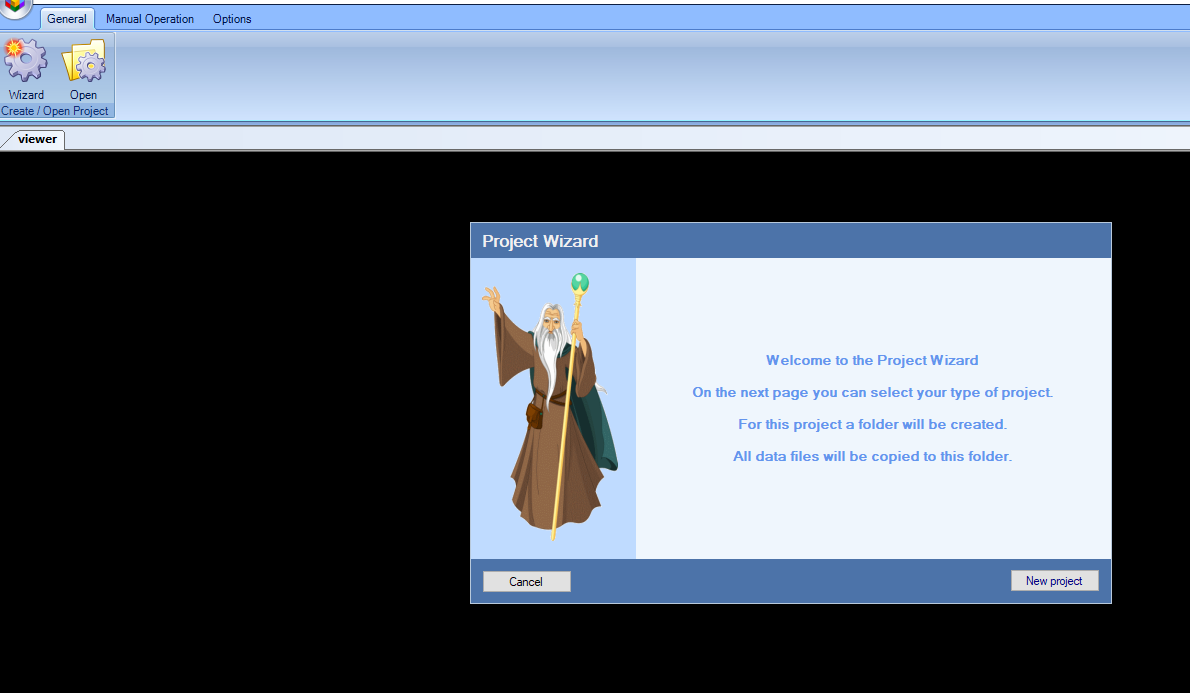
The CNC milling machine uses the RoutePro3000 software for milling. I opened it and started a new wizard to create a new project as shown.
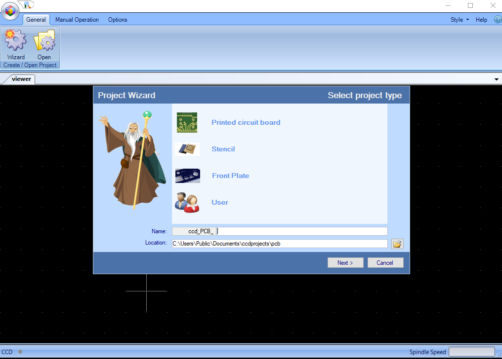
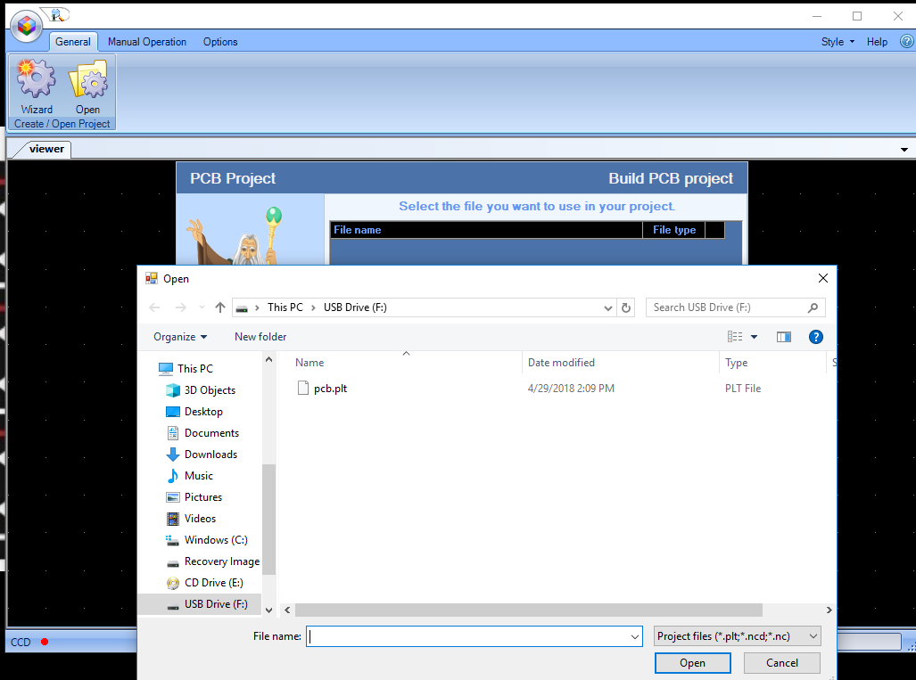
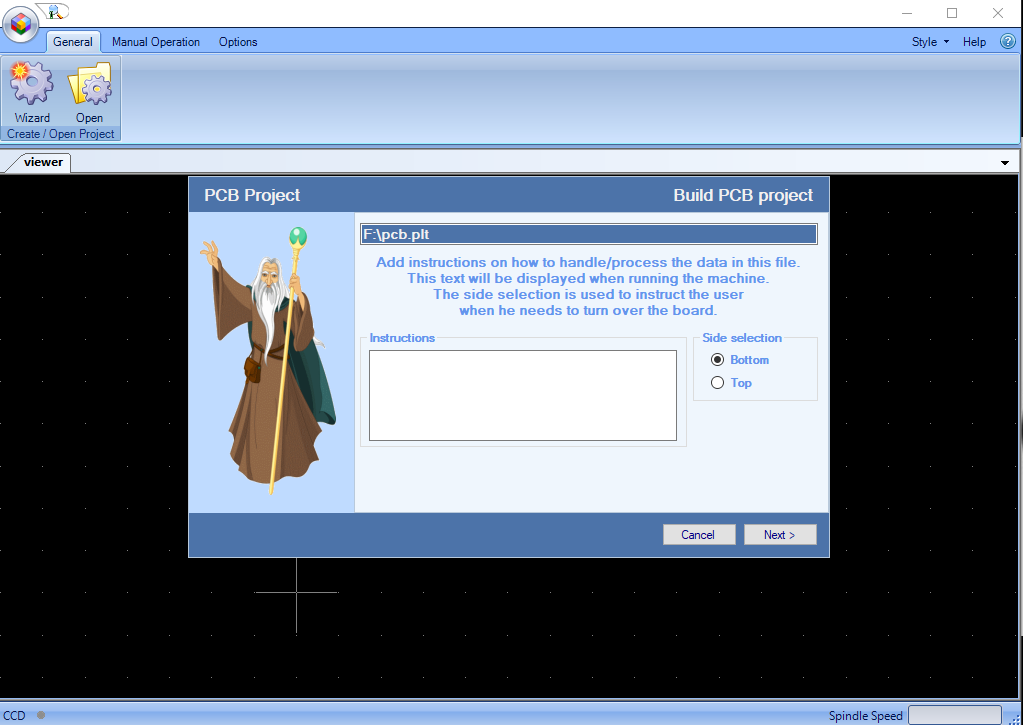
Then I selected the printed circuit board option, gave it a name at the input field. Pressed next to choose the plt file.
Select a side either top or bottom.Then next
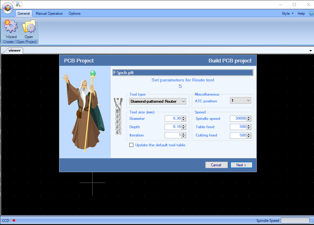
It shows you all the parameters as shown.
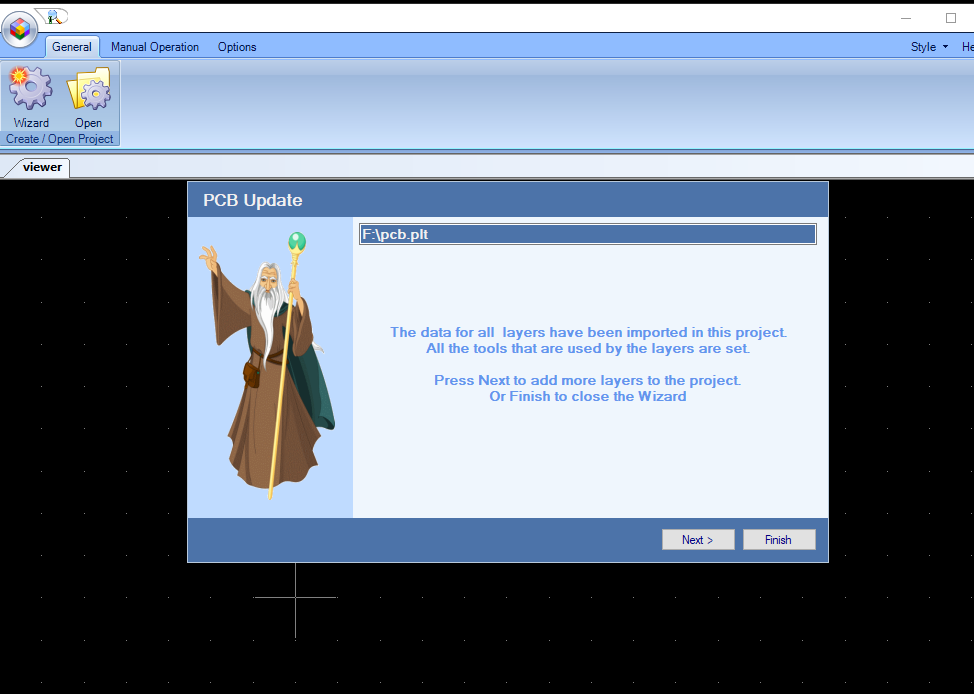
Once done it imports your board as shown.
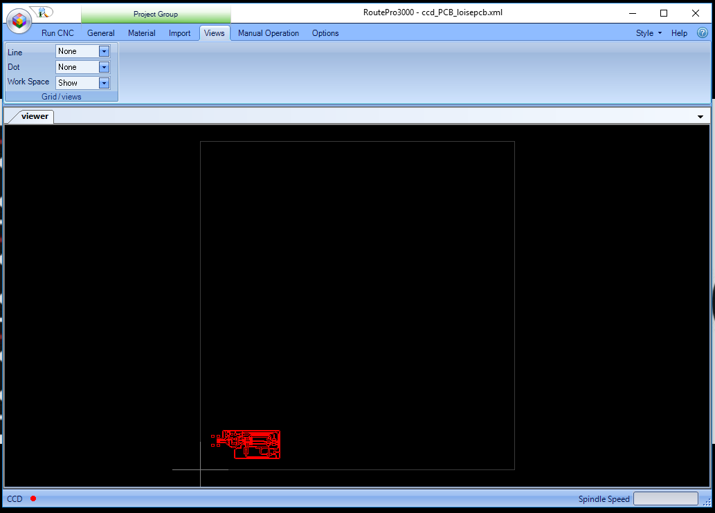
Under Views you will see the workspace option is hidden. To be able to view just click show option.
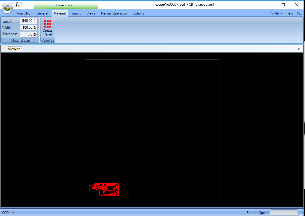
Under Material I used a board which was 1.7mm.I entered its thickness in the thickness input field.
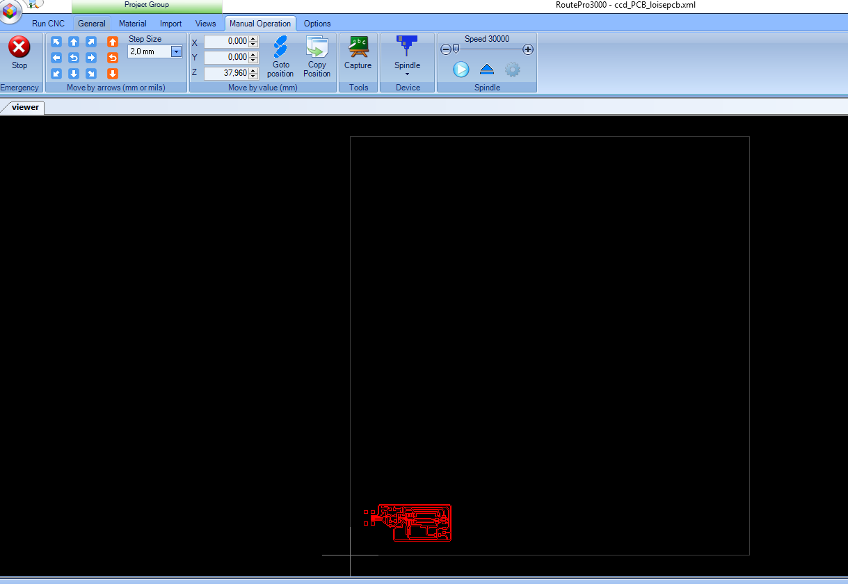
Under Manual operation I set The milling tool in the right position based on the board using the arrows buttons and step size.
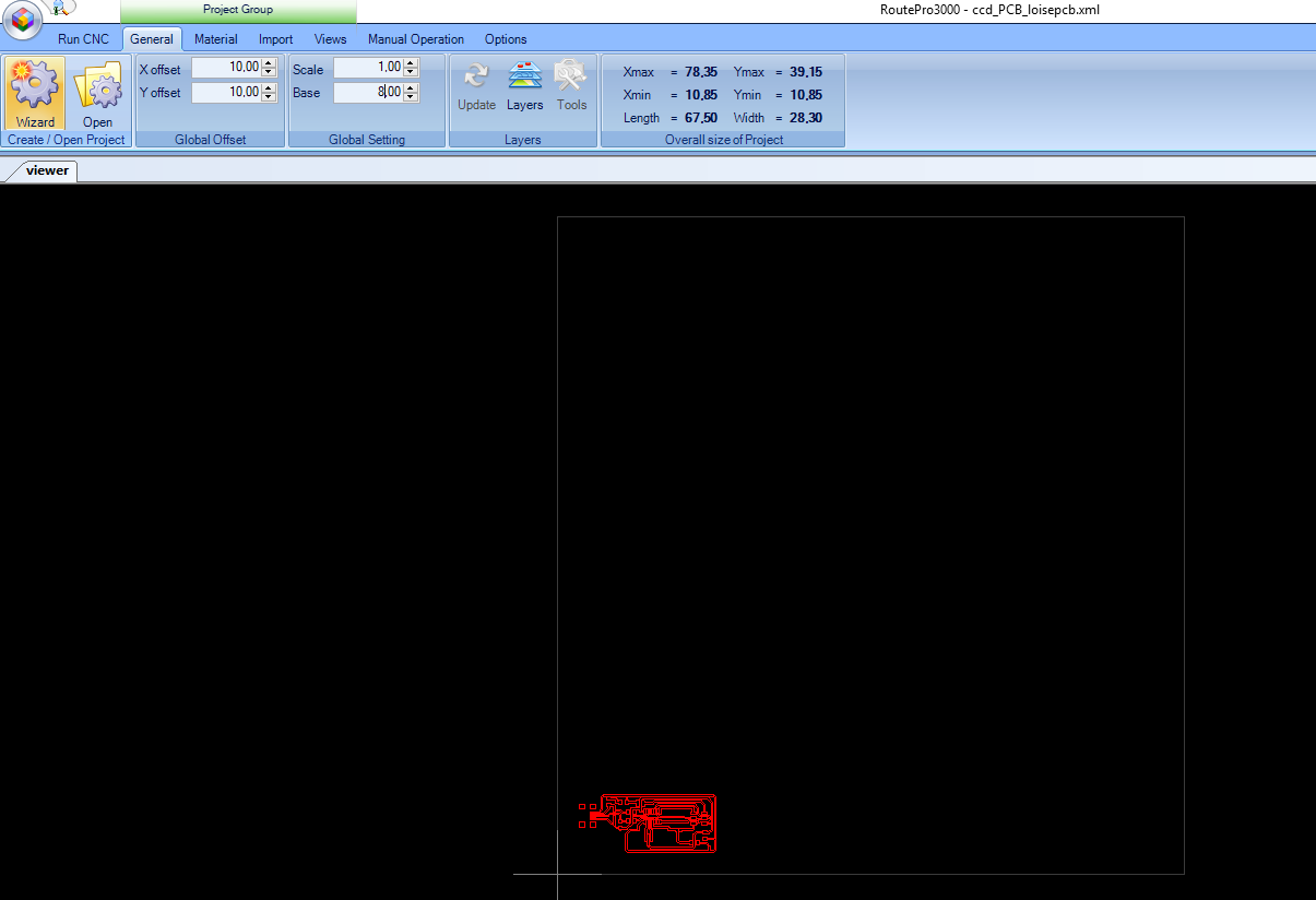
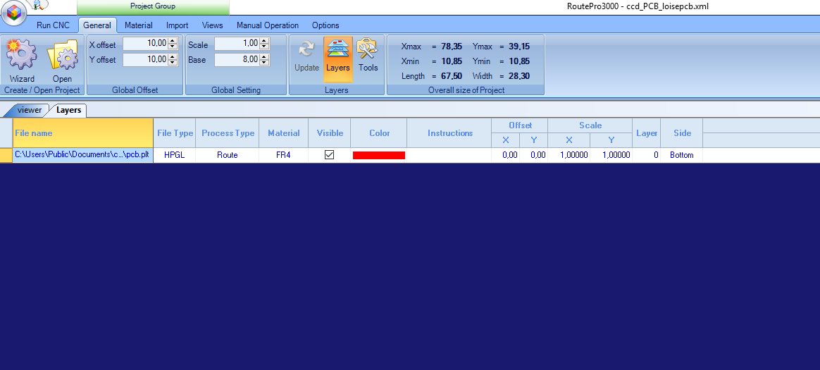
Under General I changed a few things like the base where I logged in the size of the material holding the board to be milled.THe offset I put 10 by 10 for both the x and y axis.
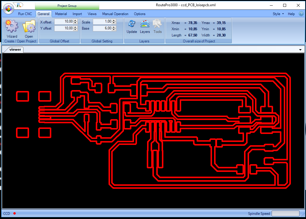
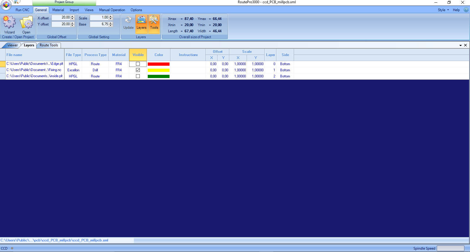
Under Layer it gives you details of your milling work as shown.
Under Tools it shows you the size of your milling tool, the speeds selected, feeds and depth of your tools.Here you can edit to make the necessary changes.
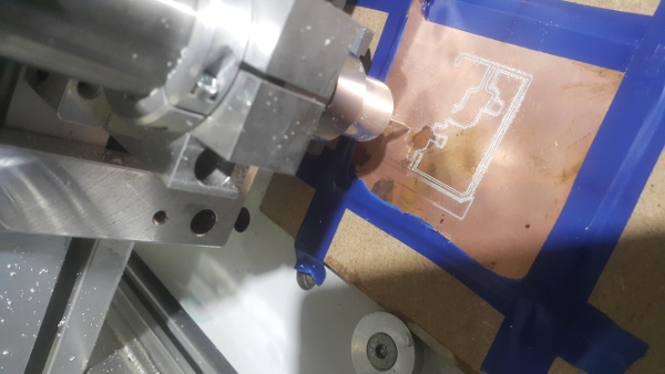
Run CNC its when the milling machine is milling.At first I did a test run with a sample board before I could start milling the other boards.

Challenges
While milling the test board some part of the board was not milling properly and had to adjust the level of the tool and checked if the surface was leveled properly.
Before
After
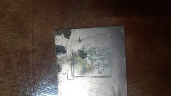
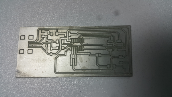
After milling the pcb board.
I used the tinning solution to tin the board to help minimise oxidation.
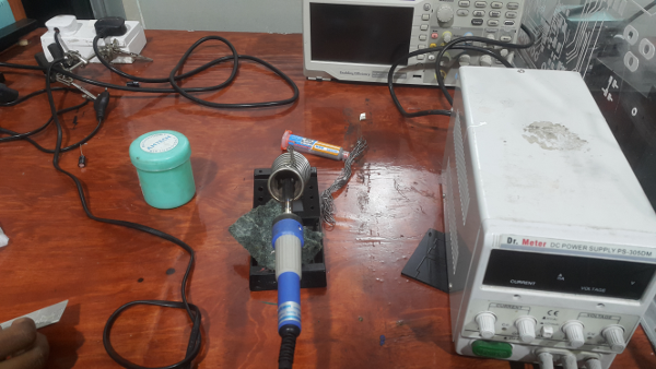
Soldering process
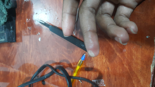
In this case am using several method then I get to choose which I prefer.At my disposal is the soldering paste, soldering flux , solder wire and soldering machine. I had never soldered before so my instructor took me through the soldering process and taught me a few ways to handle the solder iron.
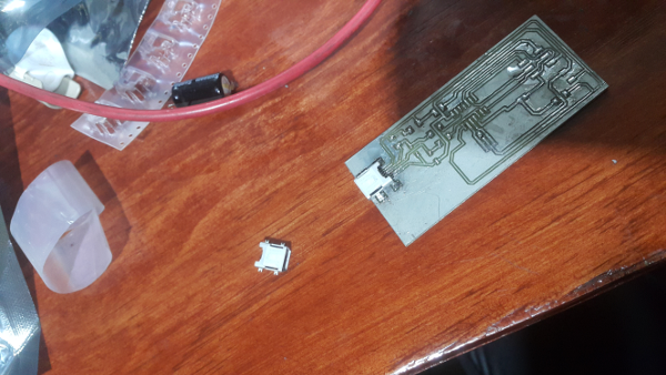
I used the solder flux to oil the board to avoid solder from geting to the lines and causing short circuit. Then I used the solder paste, you just apply a little on the board then you blow it using a hot air rework station don't use too much heat. Then i used the soldering wire for other parts of the board as shown.
I happened to burn myself a little while I was soldering, i touched the hot part accidentally.
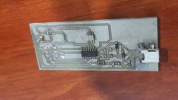
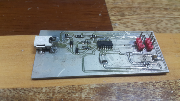
I populated the board with all the components as shown.I prefered the soldering wire processs because it was a bit cleaner on the board than the solder paste.
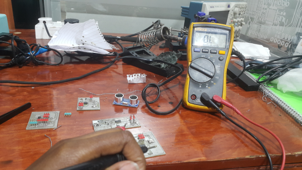
I used the multimeter to test the continuity of the board.
Programming
Smoke test
I followed the steps in tutorials to program the board;
Plug the FabISP into your computer via the mini USB cable.
a). If you get an error message from your computer that the board is drawing too much power and that the computer is shutting down the USB port.You have a short somewhere on your board.
b). If you do not recieve any messages, proceed to "Install the necessary software for AVR programming."
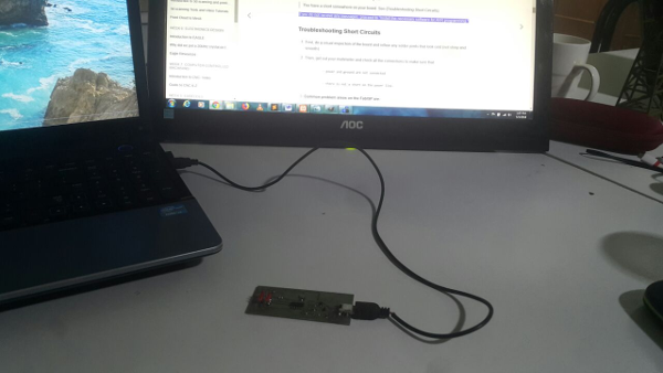
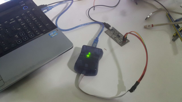
In this case I plugged tha fabisp using the usbmini cable to the computer and I did not get any error message.
Installing softwares
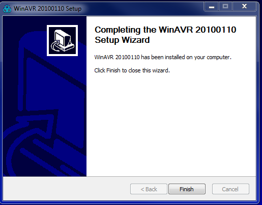
Since am using windows I installed the WinAVR as shown.
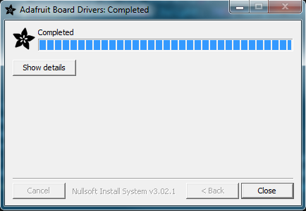
Then I downloaded drivers for windows.
After installing the softwares I connected the fabisp to the computer both the usb connector and programmer as shown. It installed the drivers for usb on the computer successfully.
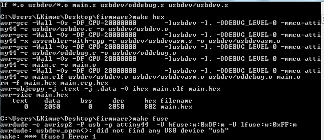
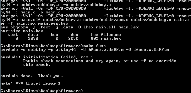
I started programming the board through command prompt.I cd into the firmware directory in the desktop then used the make clean command as from instructions to compile the firmware. It gave me a successful message then I run make hex it also gave a successful message.The next command is make fuse which returned an error as shown below.
Challenges
The command for make fuse brought an error. I looked for solutions and one of them was to edit your code to the specific programmer you are using, in this case i changed it from AVRDUDE = avrdude -c avrisp2 -P usb -p $(DEVICE) # edit this line for your programmerto#AVRDUDE = avrdude -c usbtiny -p $(DEVICE) # edit this line for your programmer.The same erroe appeared again.
The next solution i tried was to check my soldering connections which i soldered again then tried again, I got the same error.
I decided to test the continuity of the pin headers for the programmer I found that not all were connecting there was a discontinuity.
Solution
Finally my instructor instricted we try using her machine since she has linux operatong systems. while at it, the circuit had the same error of make fuse so I decided to check the connectivity. then tried again.
Make Fuse
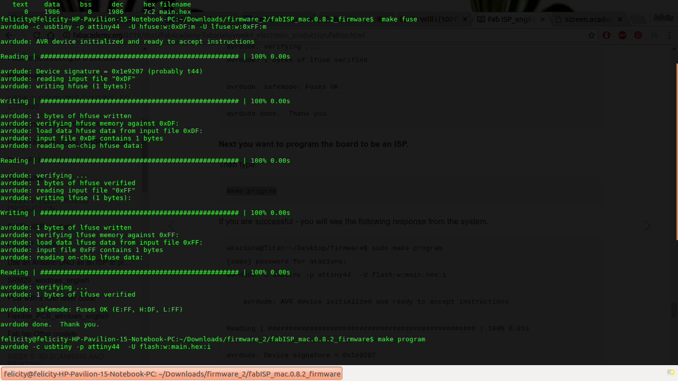
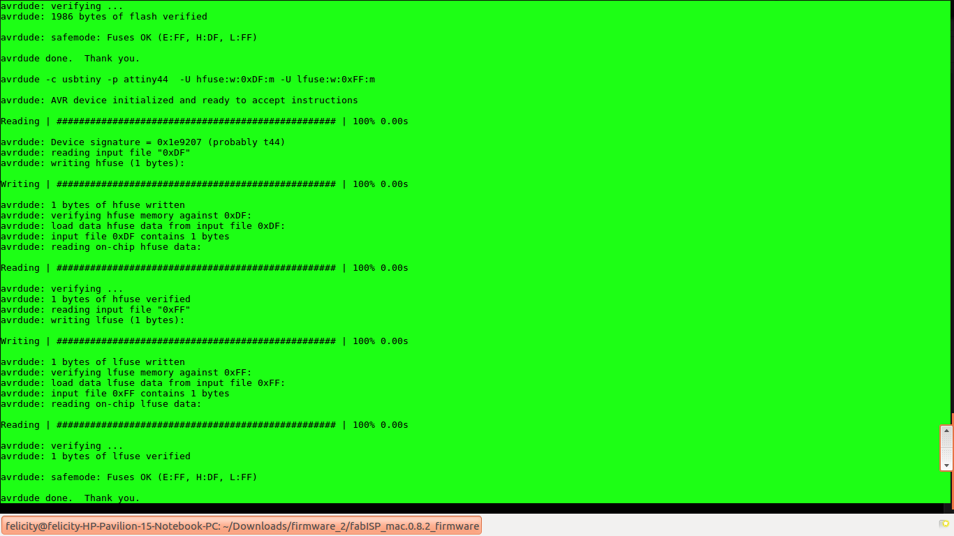
Make Program
Make program gave error at first.I found out that the Crystal was not properly soldered hence soldered it then tested a gain it gave the following results.
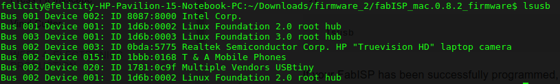
Testing
To test I typed the command lsusb on terminal and the results were as shown. The device was seen as Multiple vendors USBtiny