By the end of this week we should be able to communicate between two devices wired or wireless. I'm so disappointed because nothing works with me whatever I tried. I worked with WIFI, Bluetooth but there is no success until now :'( .
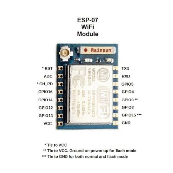
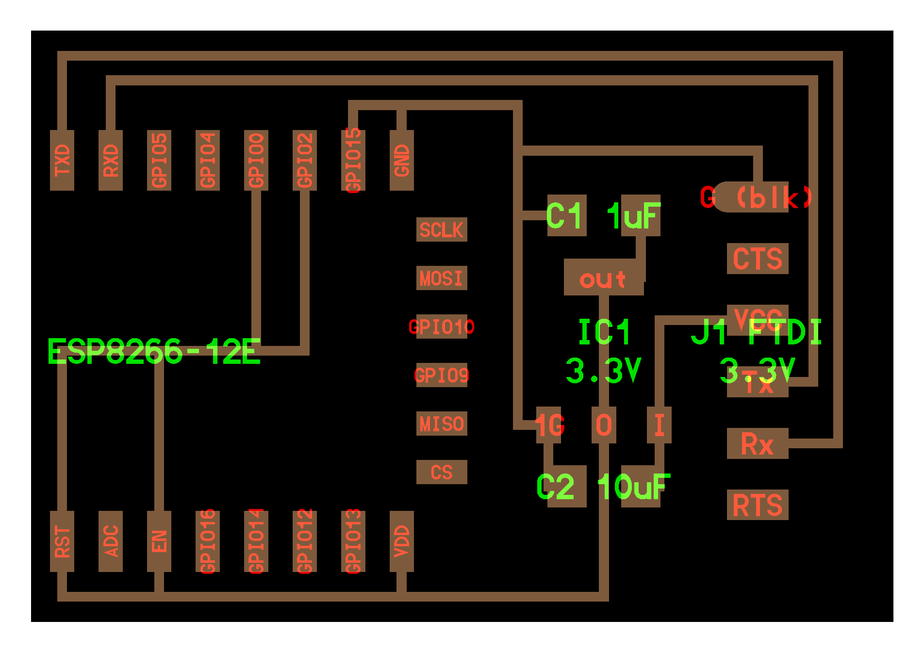
I used ESP8266_07 WiFi module. Chip pinout shown below. For more detiales about connections, modes and AT command read THIS DATASHEET
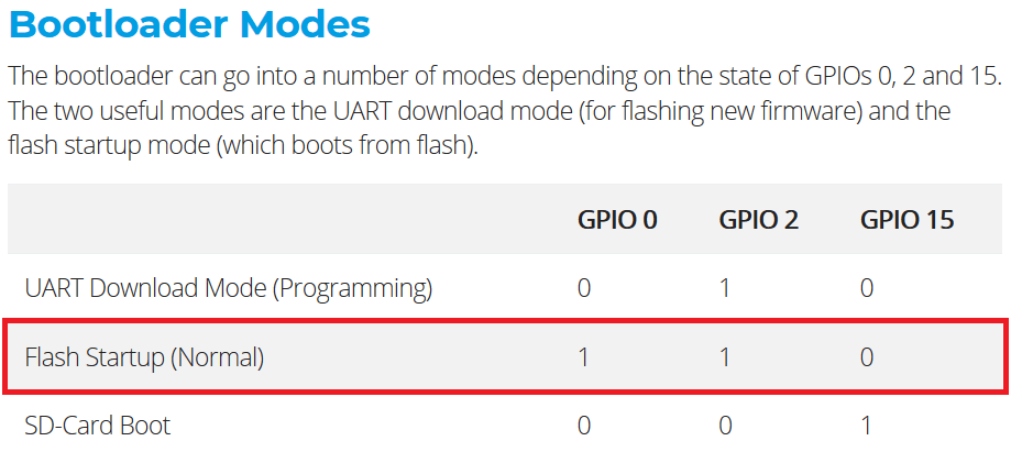
I imitated the hello.ESP8266-12E board by Neil but I changed the required connection due to the difference in the chip pin out making sure the chip will connect at Normal Bootloader Mode shown in the table. This is my EAgle design:
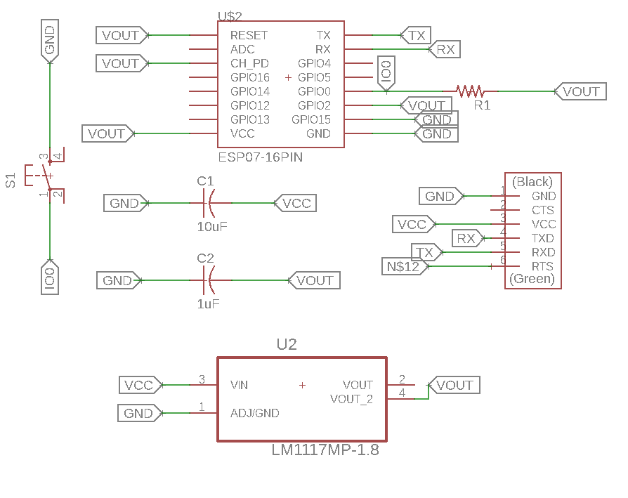
This is my Eagle schematic design:
This is my Eagle board layout after routing:
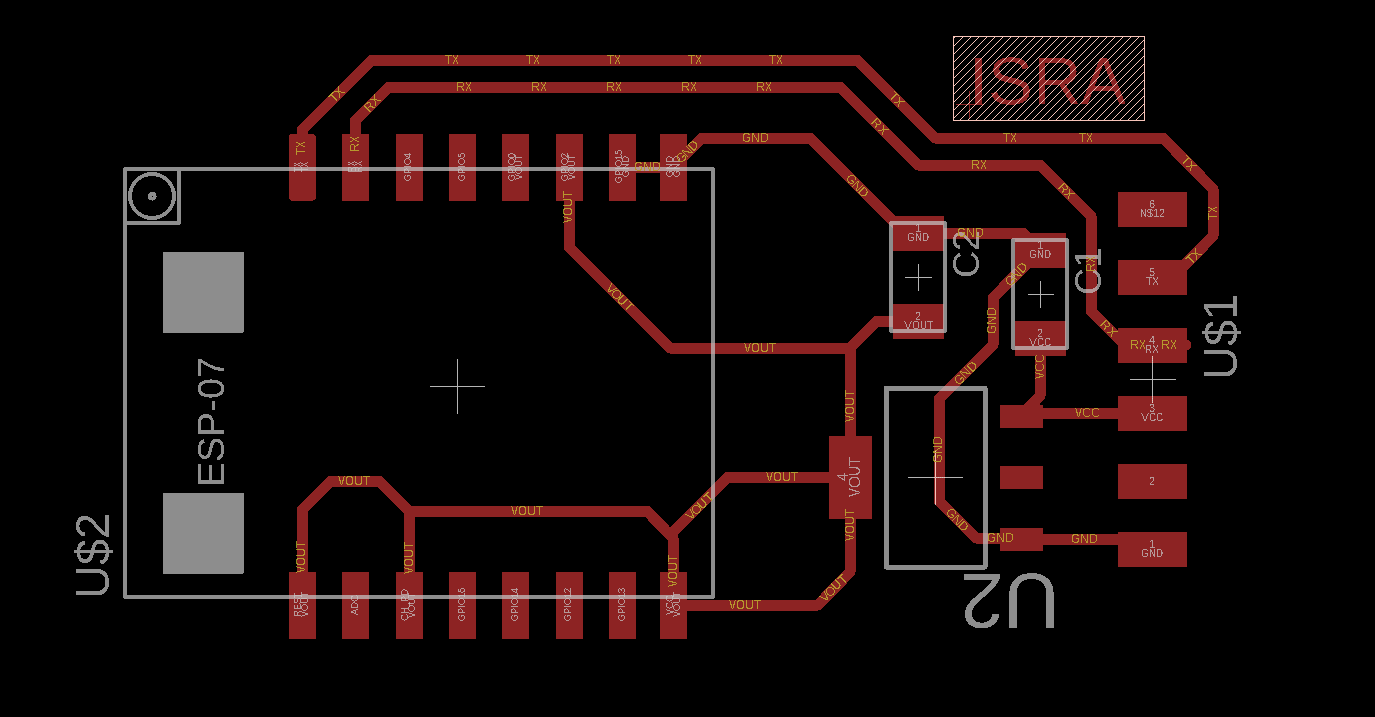
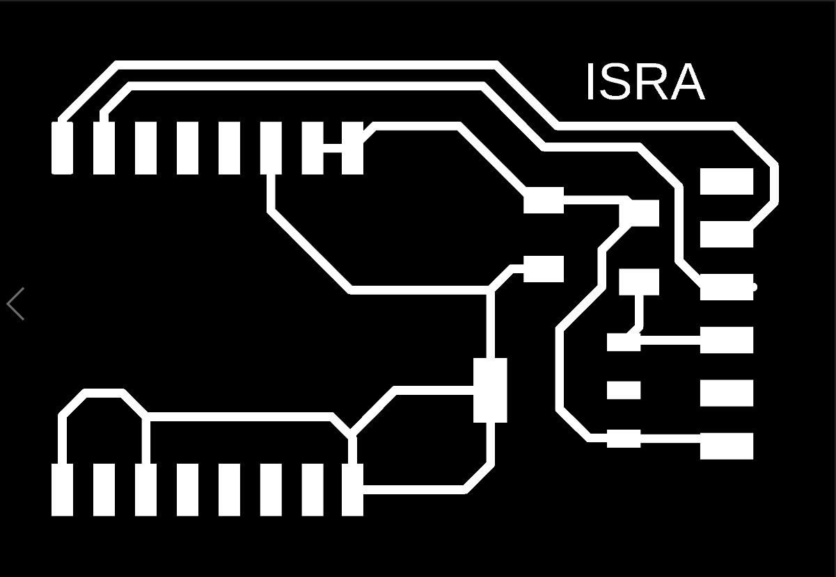
This is the ready exported image from eagle, which will be transferred to Fabmodules to set milling settings.
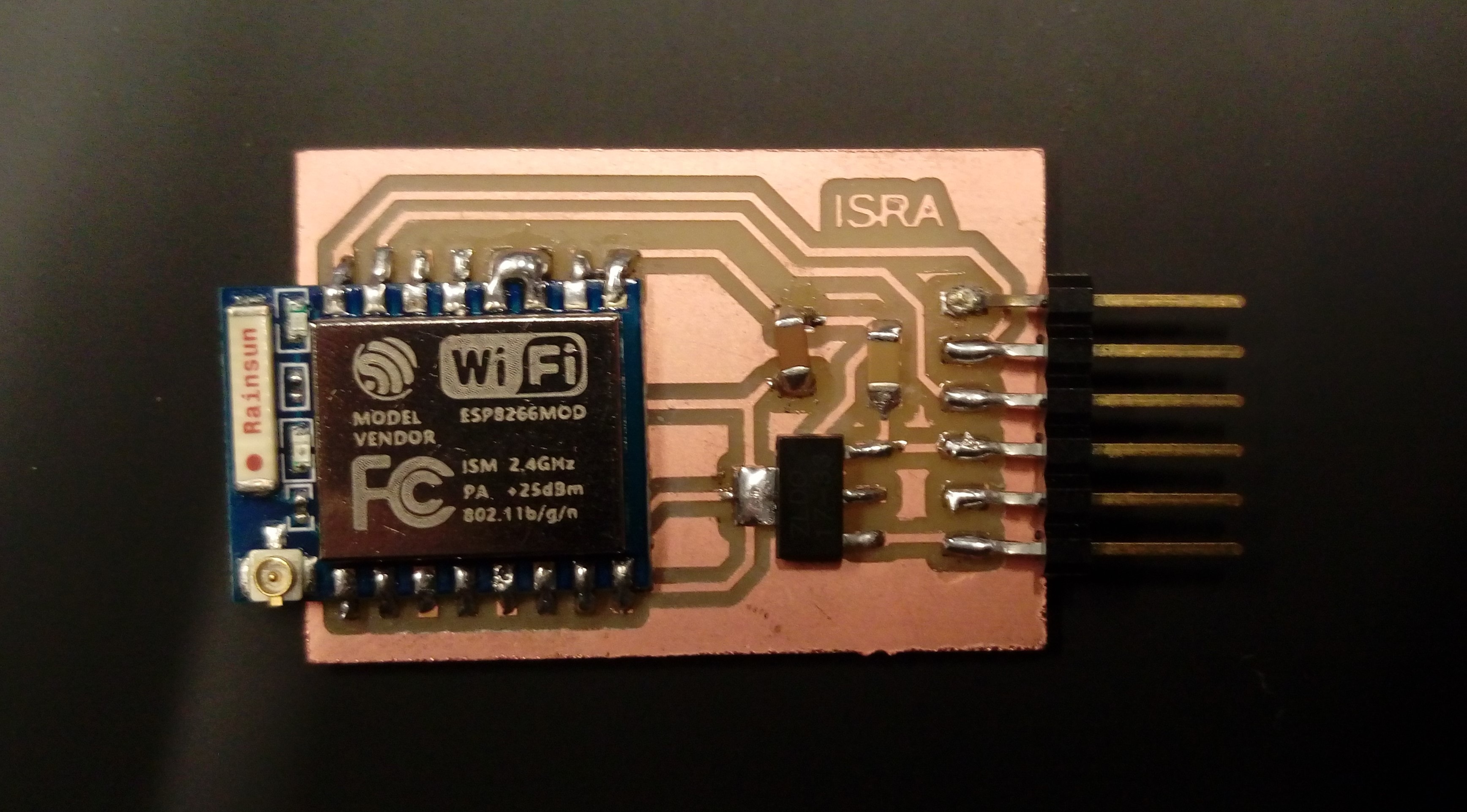
Then I followed the procedure which I did in Electronics Design week to fabricate my board and solder it My final results:
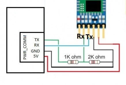
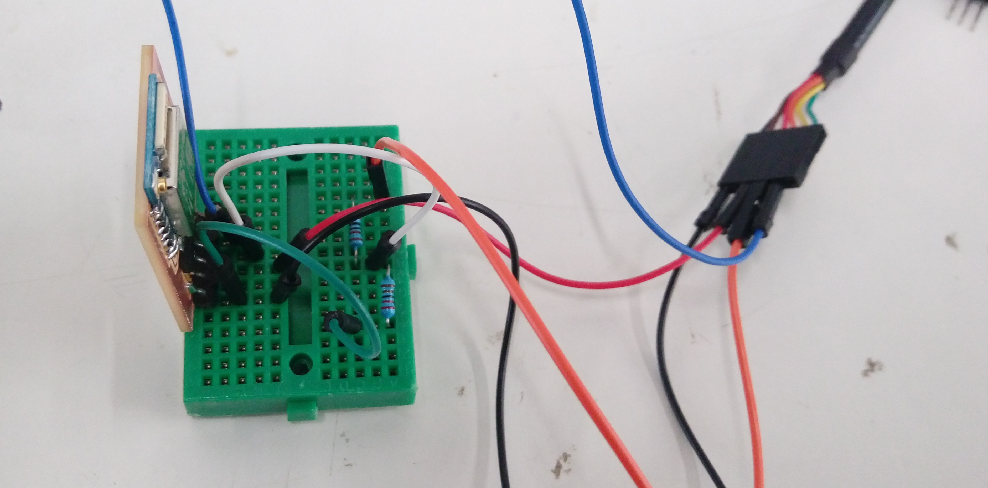
Now I should connect ESP 07 chip to my laptop USB port using 3.3V FTDI because ESP 07 should be connected to 3.3V not 5V. But unfortunately this cable wasn't in the lap when I star working so I tried to use a simple voltage divieder circuit shown below. Unluckily nothing works
So I just try to connect ESP 07 directly with 5V FTDI cable without voltage divider as shown:
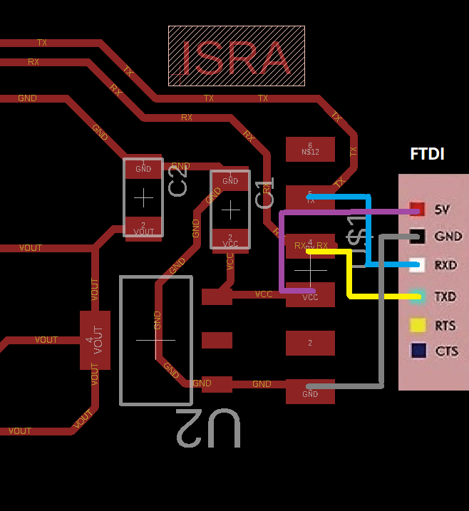
I know it is a stupid decision, but I just tried and it worked!!!!!!!!
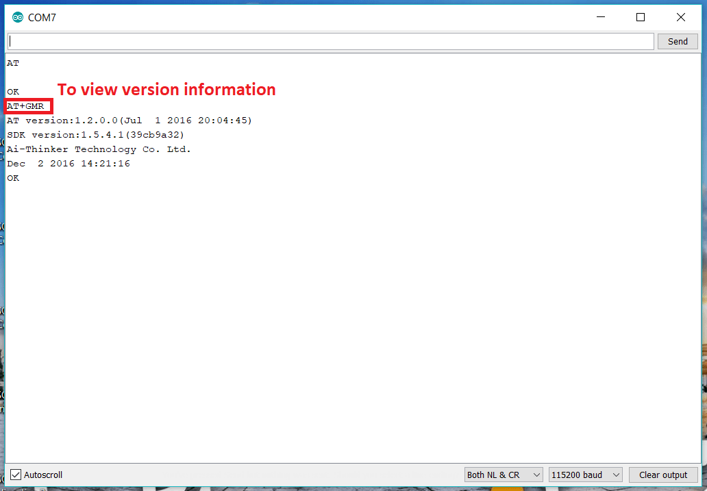
. I open Arduino IDE serial monitor and change baud rate to 115200 which is the default for this ESP chip. Then I started sending AT commands through it. The first command was AT and the response OK which mean that it recognized ESP chip.
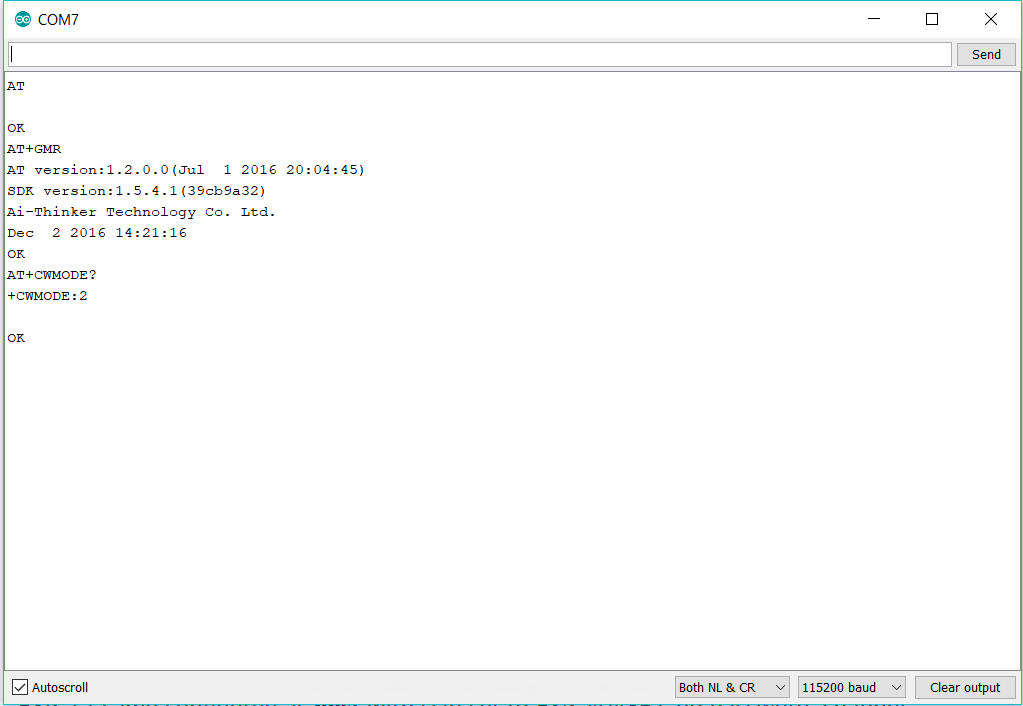
Check the WiFi mode using AT+CWMODE? there is three modes 1 is client. 2 is host and 3 is dual mode. My chip is in host mode now.
Try to create a network using AT+CWJAP="NAME","Password" first several tries failed because of wrong in typing the commands.
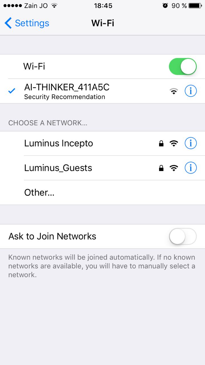
Finally, it works and connected to my phone this is default name
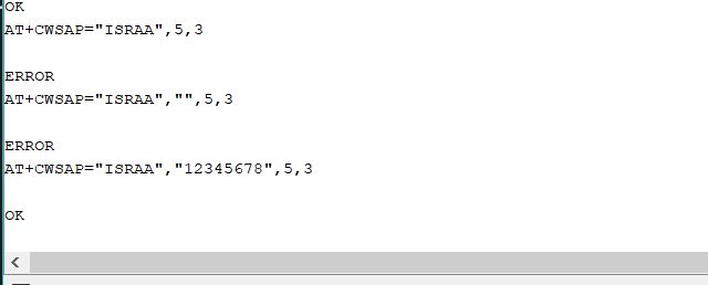
Change the name and set a password using this command:
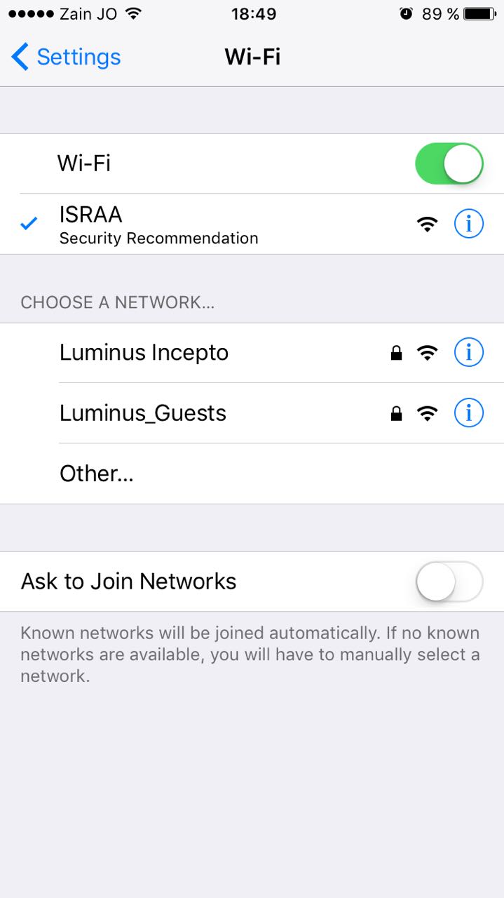
My phone connected to my network:
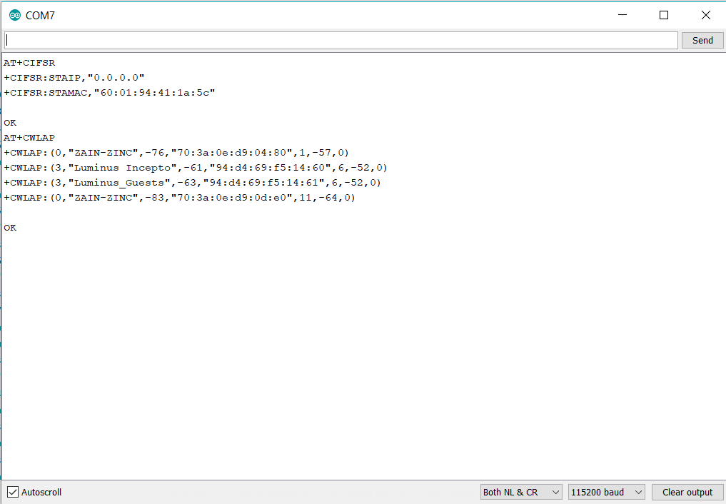
Now I will try to use my chip as a client so I changed the mode to 1 using AT+CWMODE=1 then used AT+CWLAP to list avliable networks
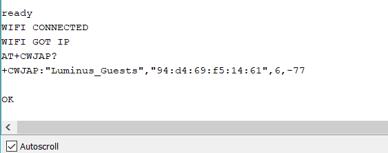
After several tries I could finaly connect to a network :)
Now I tried to use Blynk app to control Arduino using ESP board. I found this useful Tutorial on YouTube to help me using my WIFI board to control Arduino pins through Blynk application. I started as I did in the previous week with blynk settings. After some steps while I'm trying to upload the code Suddenly my chip stop response to anything it seems that it burned due to 5V FTDI connection :( I need to replace the chip then repeat everything. Unfortunately, there no more chips in the lab.
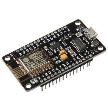
As I mentioned before, I burned my ESP board so I used ESP8266 LoLin NodeMCU V3 board.
The board's pin out:
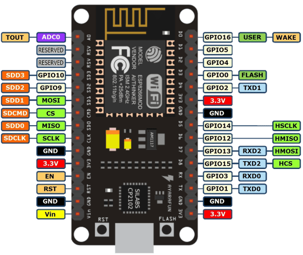
From pin out you can see the board has many GPIO: General Purpose Input Output pins which can be used as Arduino's digital pins. I want to use my smart phone to control RGB led connected with three GPIO pins. I used common Anode RGB as I did in Output Devices Week.
I started with installing the necessary libraries on Arduino IDE. Firstly, I installed Blynk application on my smart phone from App Store. Secondly, I installed latest blynk library from HERE and added it to an Arduino libraries folder.
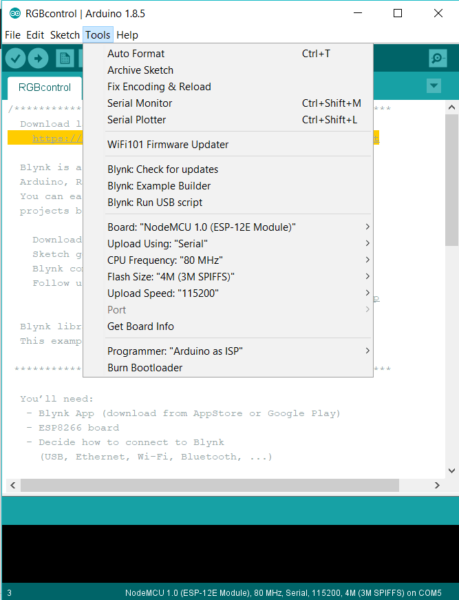
After that I followed steps in < a href=" http://henrysbench.capnfatz.com/henrys-bench/arduino-projects-tips-and-more/arduino-esp8266-lolin-nodemcu-getting-started/">This Tutorial to instal ESP8266 library, then I could choose this board in Arduino IDE.
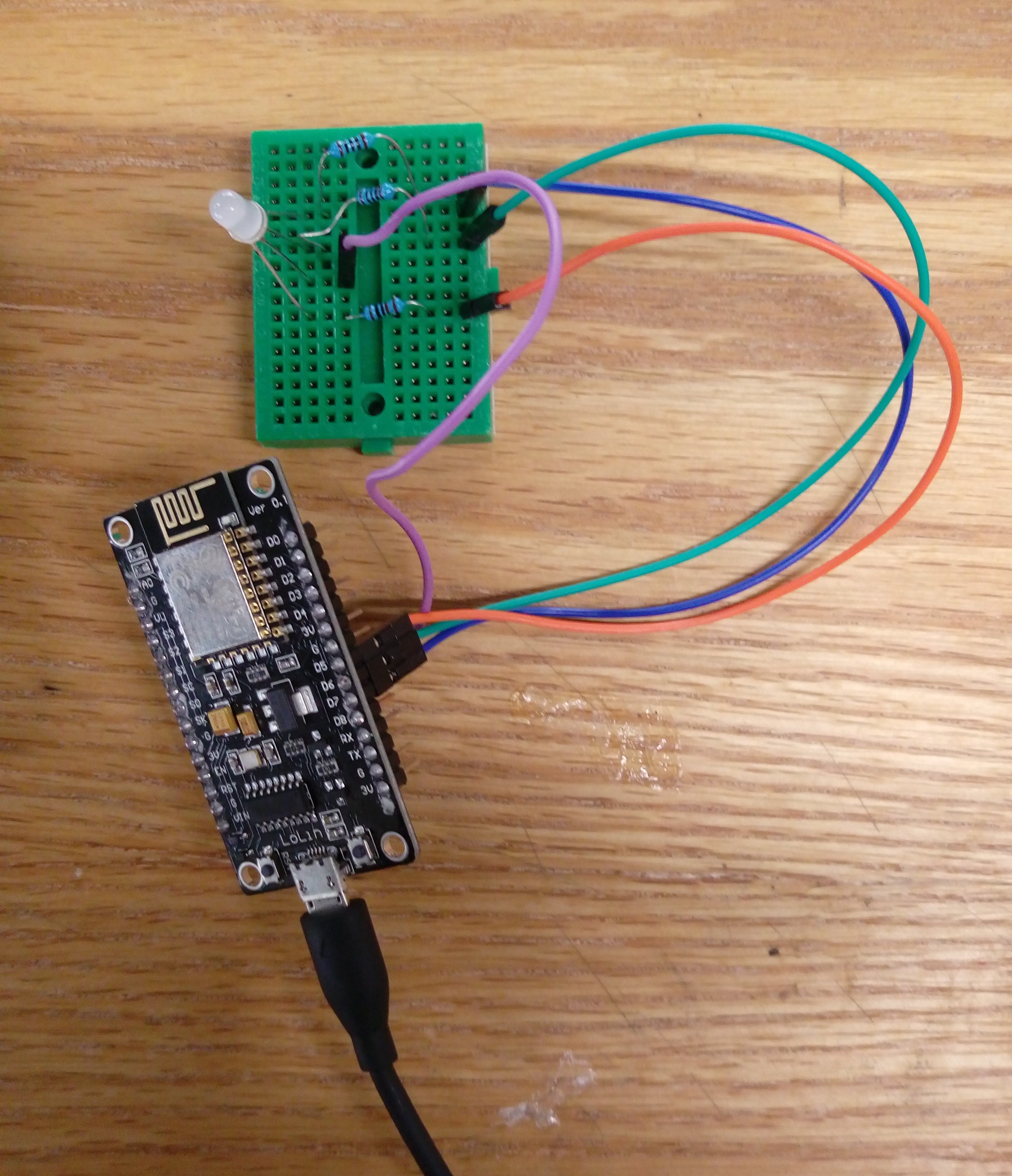
After that, I connect RGB LED with the board and connect ESP board to my laptop using USB cable.
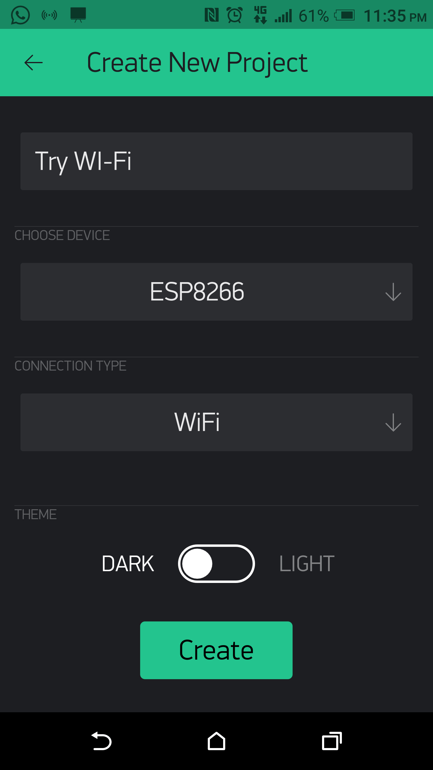
In my phone I built a new project in Blynk App. I chose device and connection type as shown:
After I pressed Creat New Project, I recived the auth token code in my email
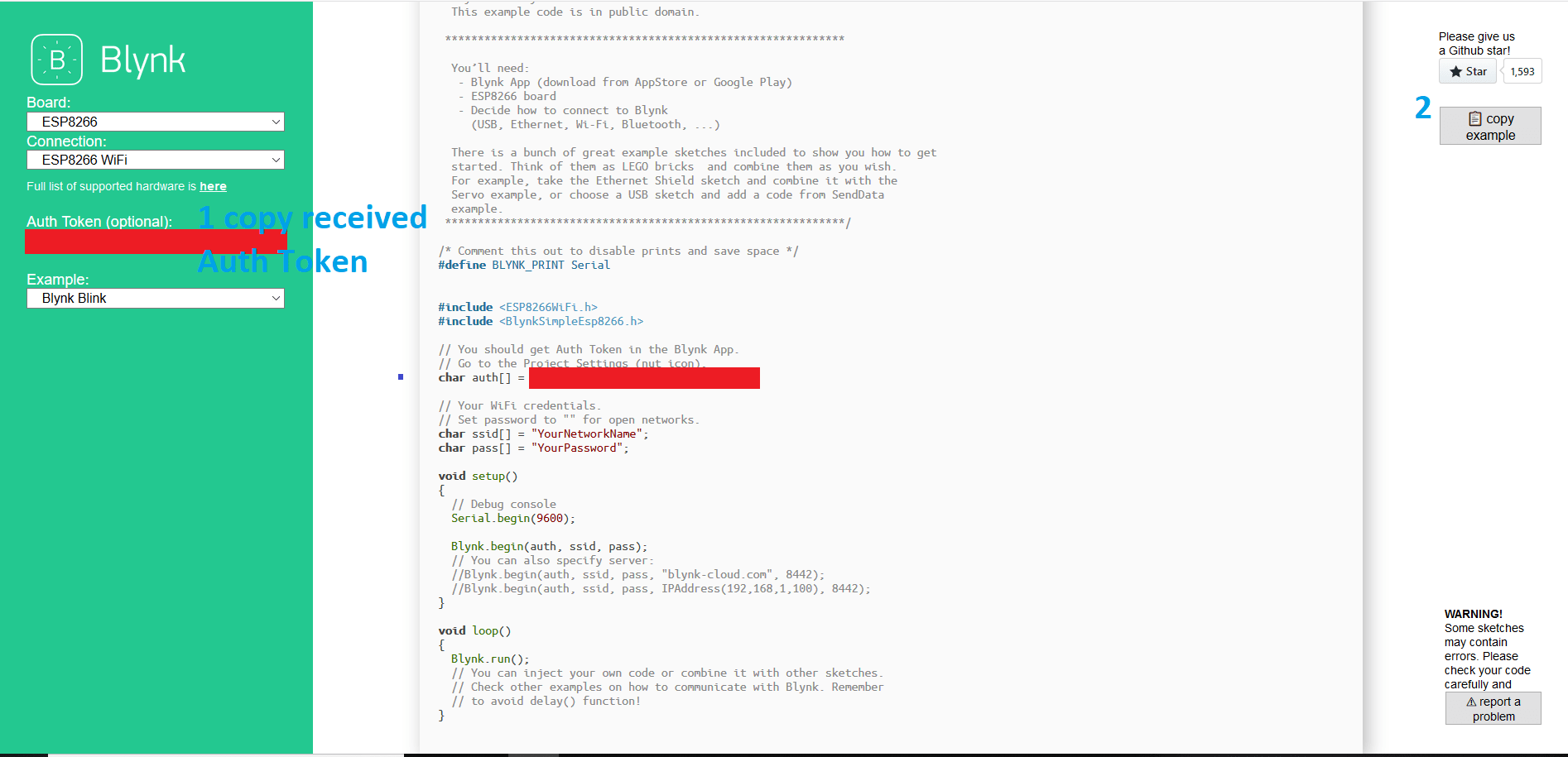
The next step was to find example from Blynk example generator page. Start by adding the received Auth Token and choose suitable example as show:
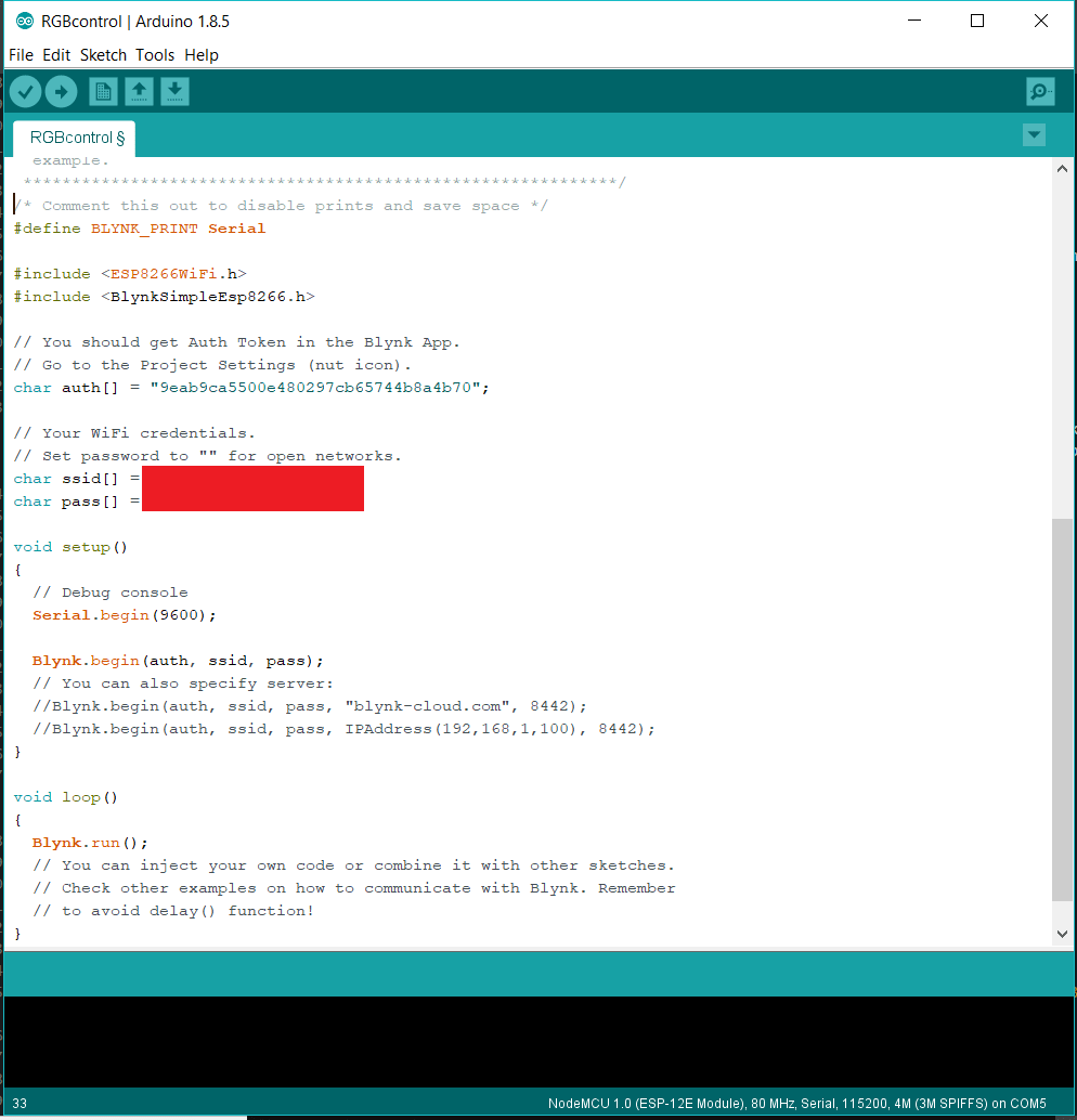
Afterwards, I simply pasted the code in Arduino IDE and carefully type the name and password of the network ( it should be the same as the network connected with the smart phone). Then upload this code to the ESP Board.
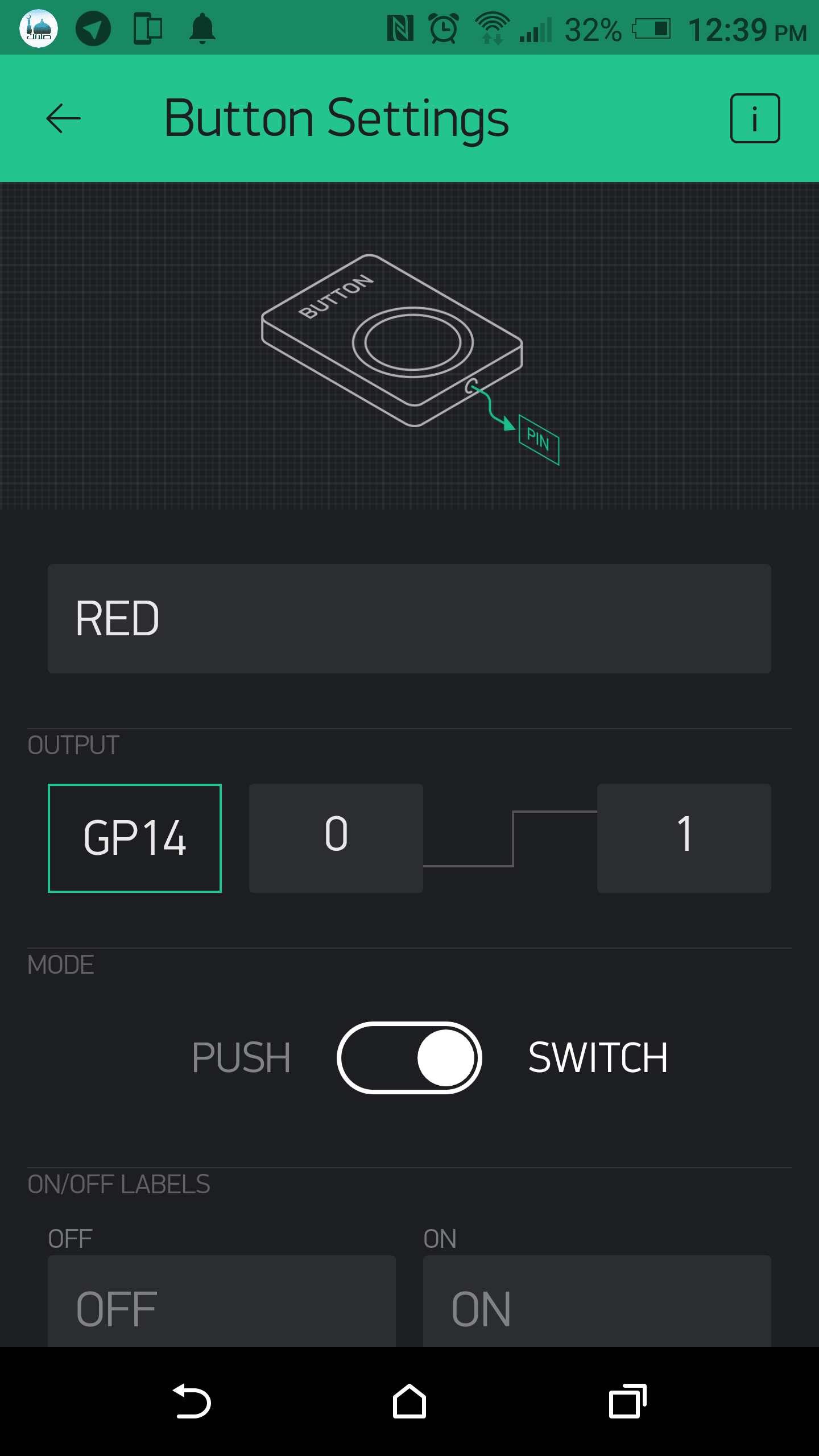
Back to Blynk App. I added a button named it RED and connect it to GP14 and change it's color to red.
Then, I repeated the previous step to to add three more buttons: Green, Blue and Button (connected to the board build-in LED). Final interface screen:
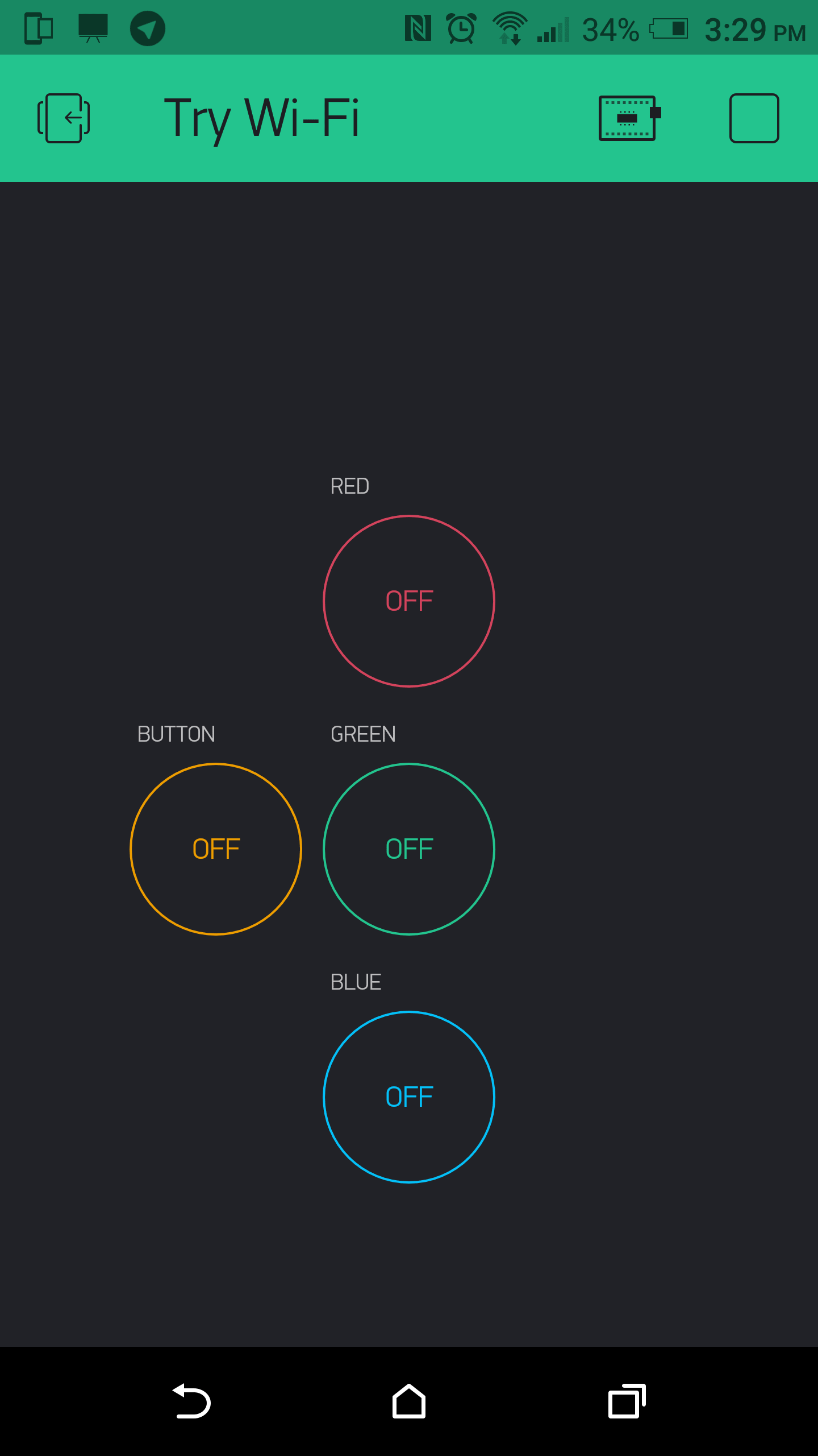
The last thing was pressing on the start button and start playing :) . IMPORTANT NOTE: I used common anode RGB which will light when button off (LOW logic), also I discovered that the build-in LED works at the same logic. To start with off leds I pressed all button as shown:
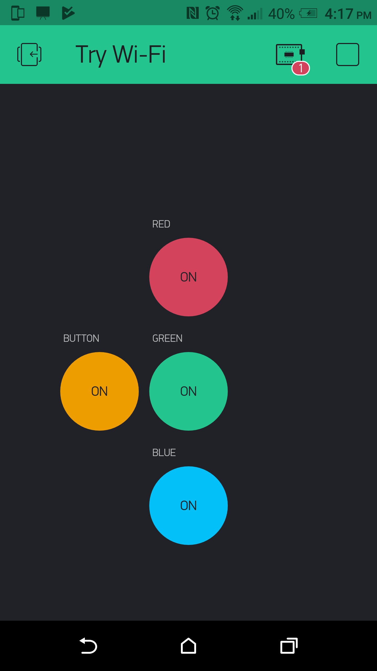
See result in this vedio
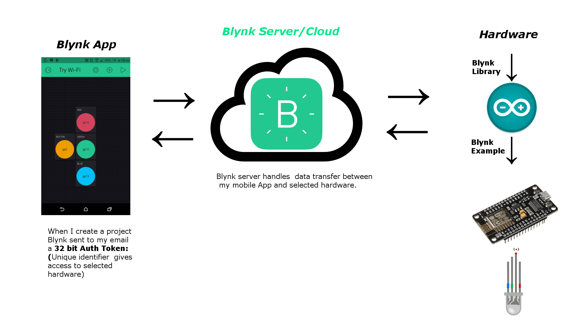
Blynk is a platform with iOS and Android apps to control Arduino, ESP8266, Raspberry Pi and the likes over the Internet. You can easily build graphic interfaces for all your projects by simply dragging and dropping widgets.
To know how it is work I read refer to This web Page.
Also for more details you can read This Page. After that I designed this picture to briefly summarize everything.
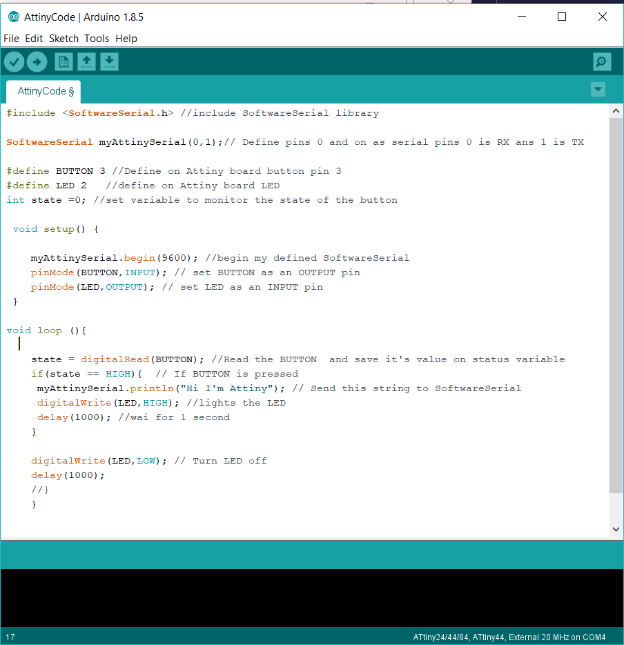
I want to let my ATtiny44 Hello board to 'talk' with Arduino UNO board using serial communication. Unfortunately, there is no hardware serial in ATtiny44 board, so I decided to use SoftwareSerial.h which is a library enables any two digital pins to behave as RX and TX Serial pins.
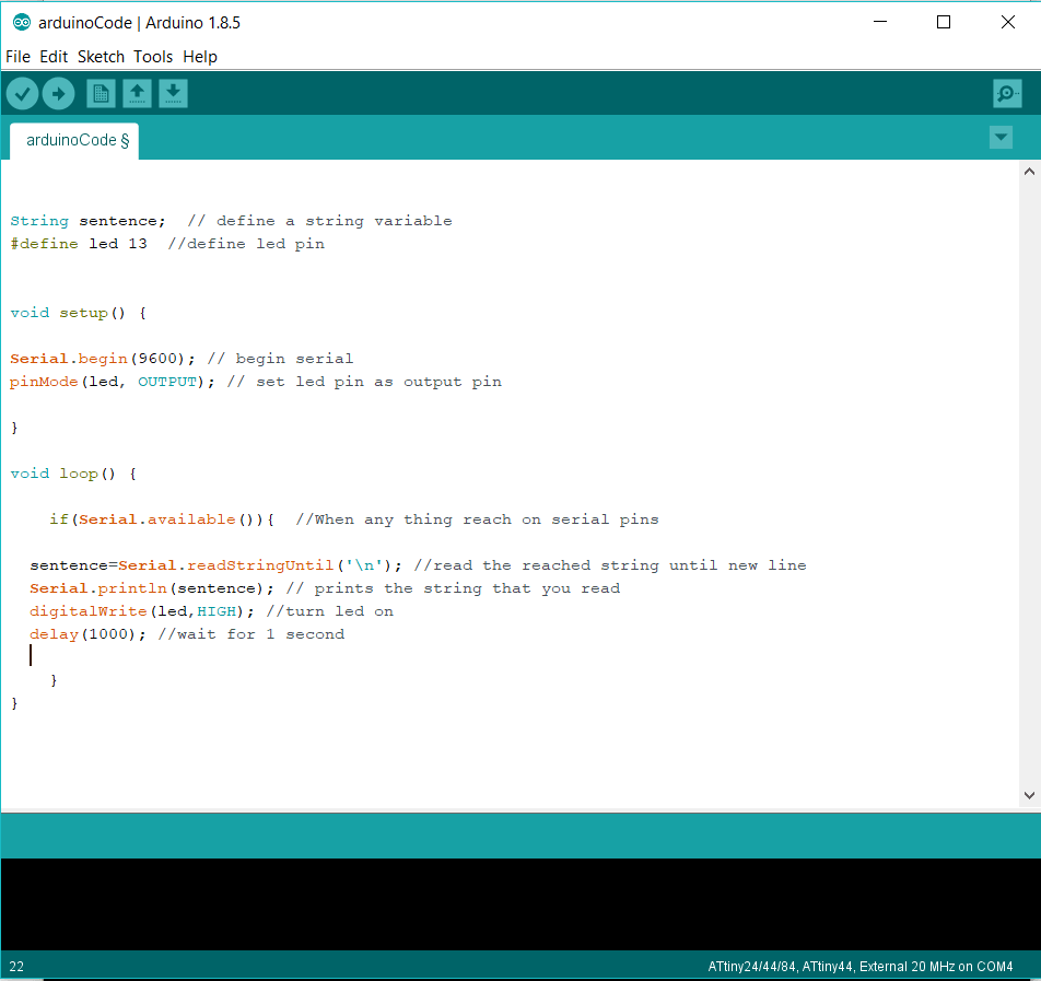
To do this task I wrote two codes. First one of ATtiny to send a string to Arduino UNO and lights an LED when I pressed the button. The second code of Arduino to print the string received from ATtiny on Arduino IDE serial monitor.
This is ATtiny code with explnation comments:
And this is Arduino UNO code with explnation comments:
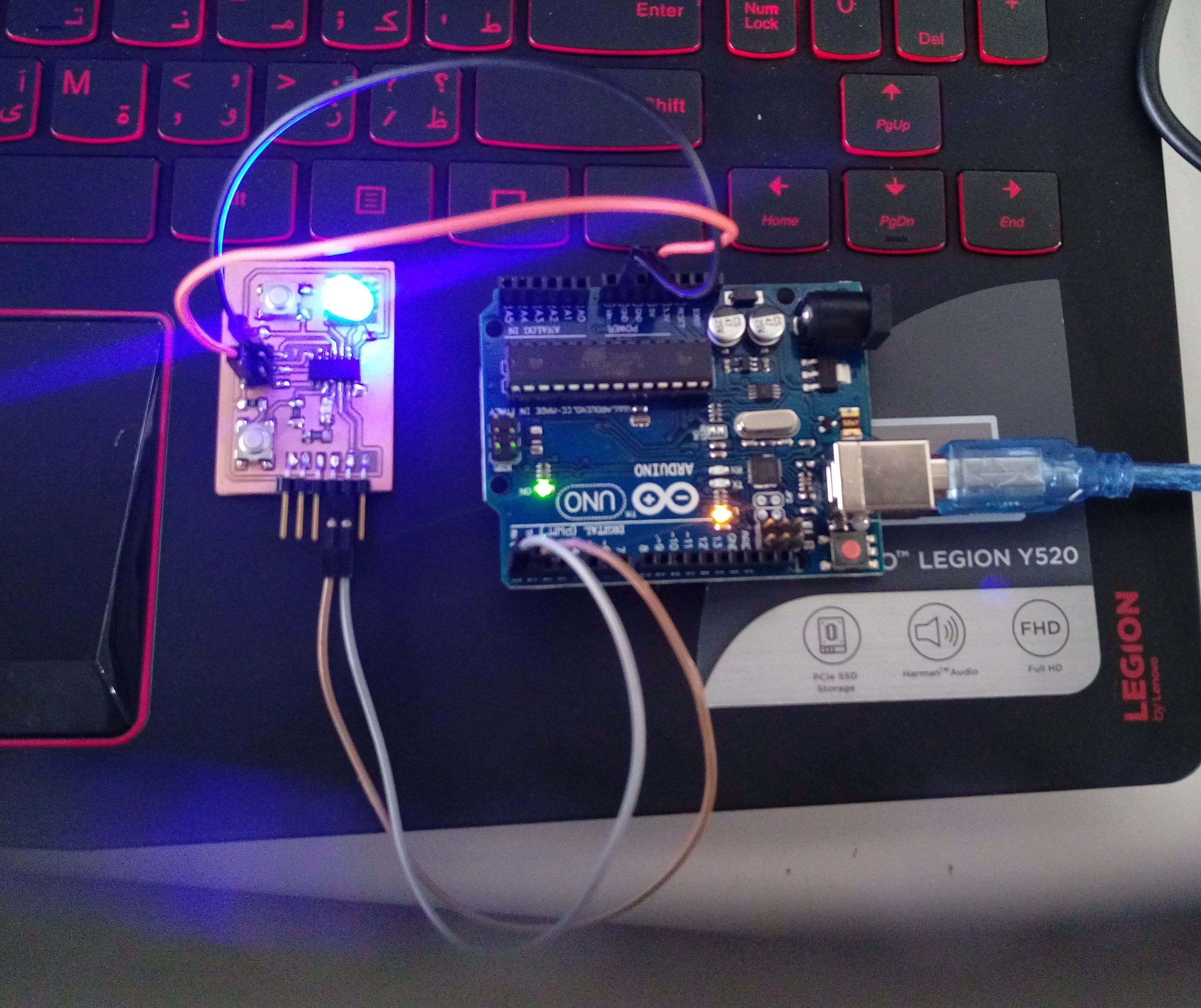
After I uploaded my code to ATtiny board as I did in Electronics Design week. I made this connection:
The connection shown in this figure:
watch this video to show my results:
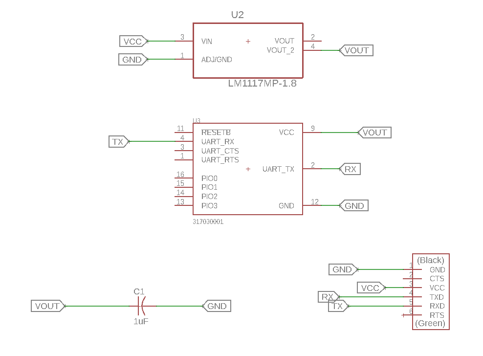
I tried to design a board of HM-11 Bluetooth module chip. This is my schematic:
This is the board layout after routing:
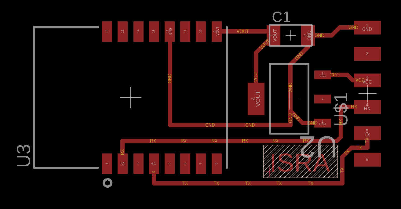
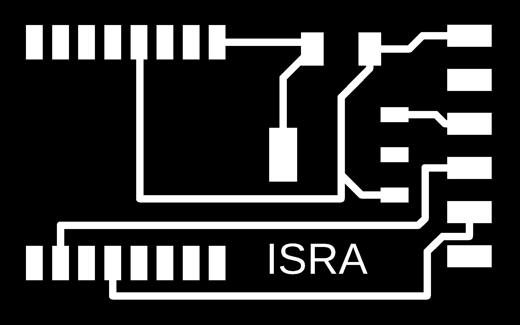
This is the traces in exported image from Eagle:
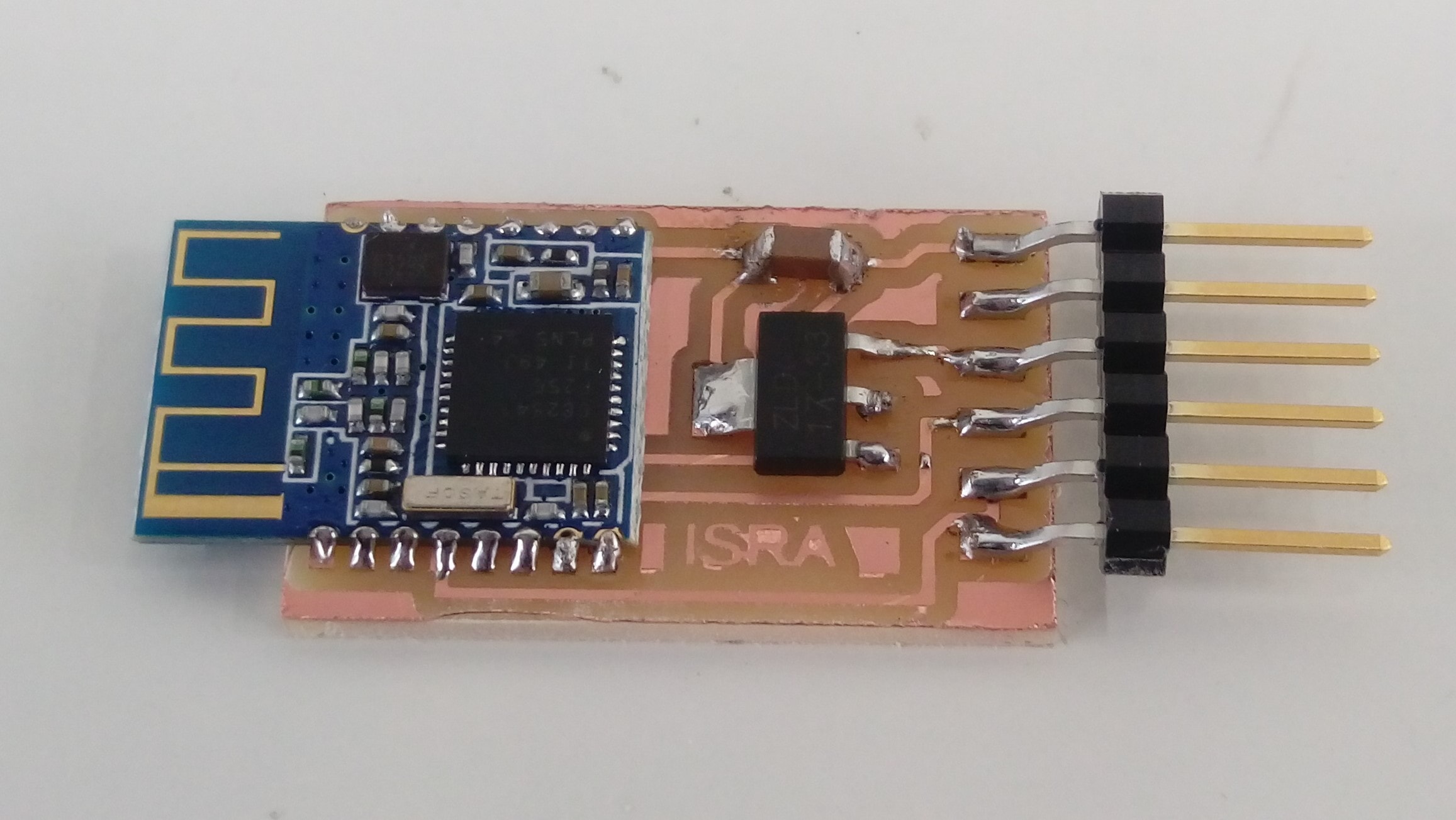
This is my board after soldaring:
After I finished my board I connect it to my laptop with FTDI cable as I did with my WiFi board. I opened the serial monitor and tried to write AT commands without any response :( .
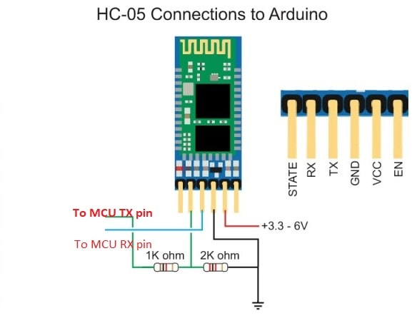
Due to time limitations I decided to use a HC-0C Bluetooth module instead of fixing my board problems. The connection of this module is super easy I just have to connect GND and VCC to power the module and connect Bluetooth TX to Arduino RX, but to connect Bluetooth RX to Arduino TX I used a voltage divider because the voltage must be 3.3V not 5. The connection shown below:
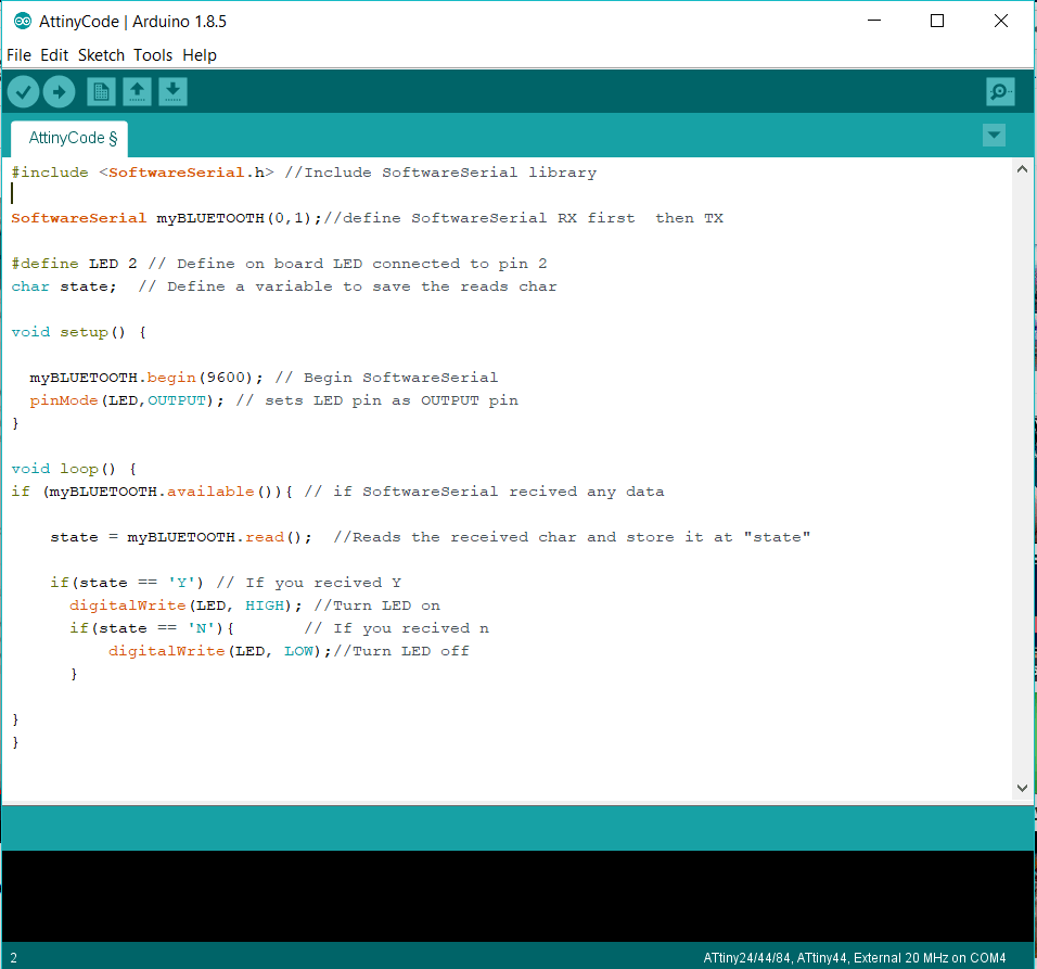
To write a code for ATtiny 44 I defined software serial as I did in a previous interface week. In my code if ATtiny serial receives 'Y' character the LED will lights and If 'N' is received the LED will off. This is my code with explanation comments:
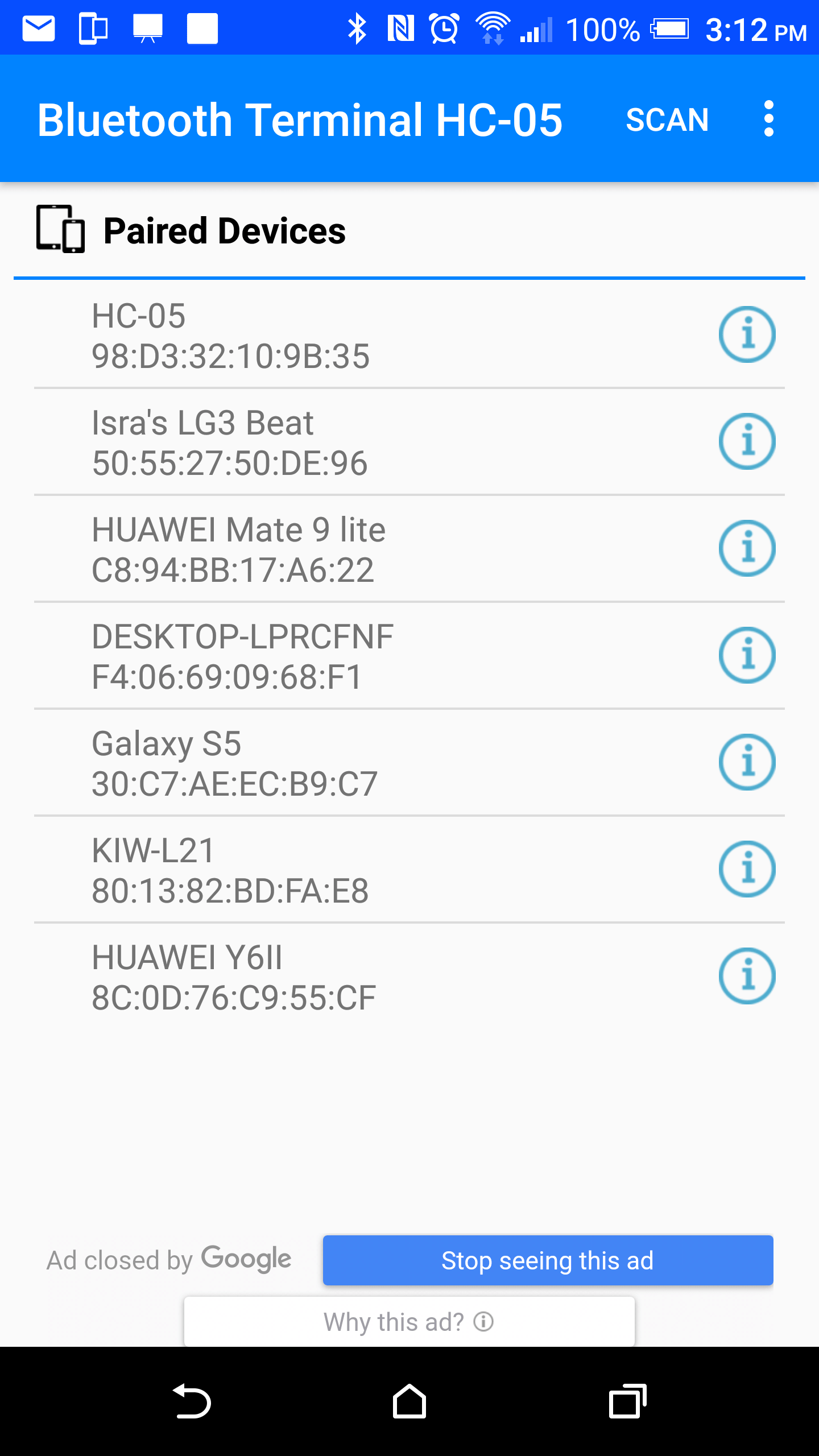
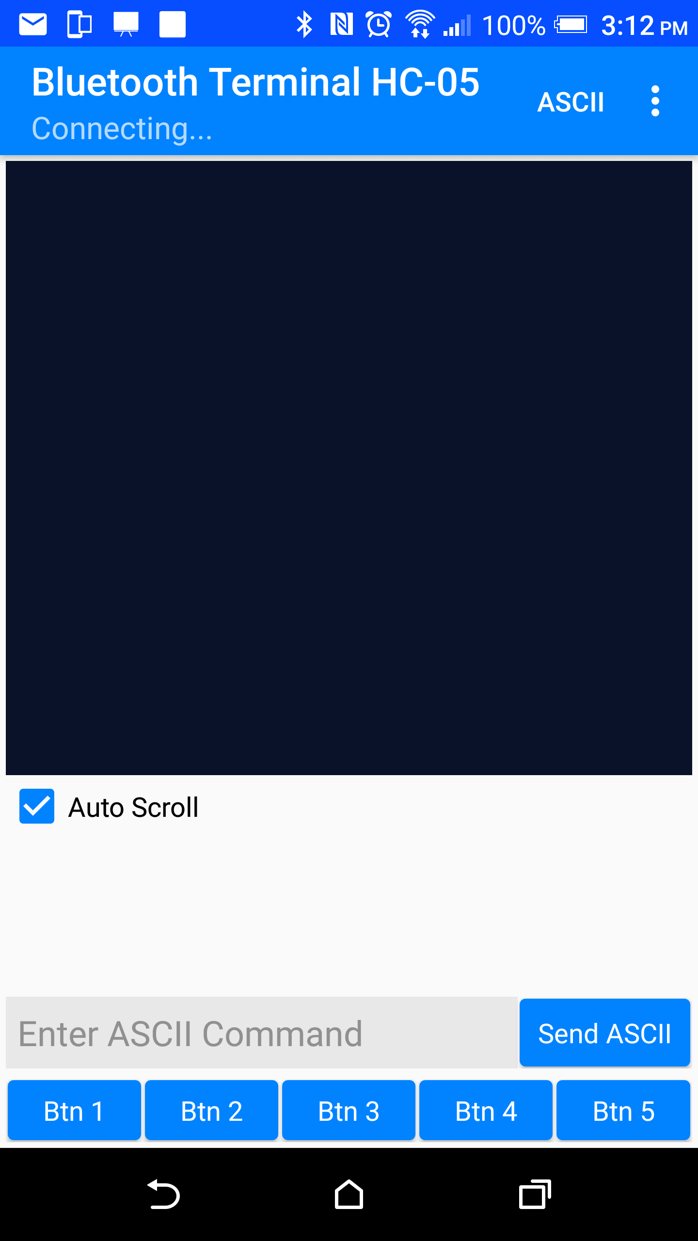
To connect with Bluetooth module and send desired data to it, I used Bluetooth Terminal HC-05 Android app on my phone. After upload the code to my AT/tiny Hello board and I connected the module to the ATtiny I could find the Bluetooth HC-05 device and connect to them to be able to sendthe required data to control the LED:
Watch the results in this vedio:
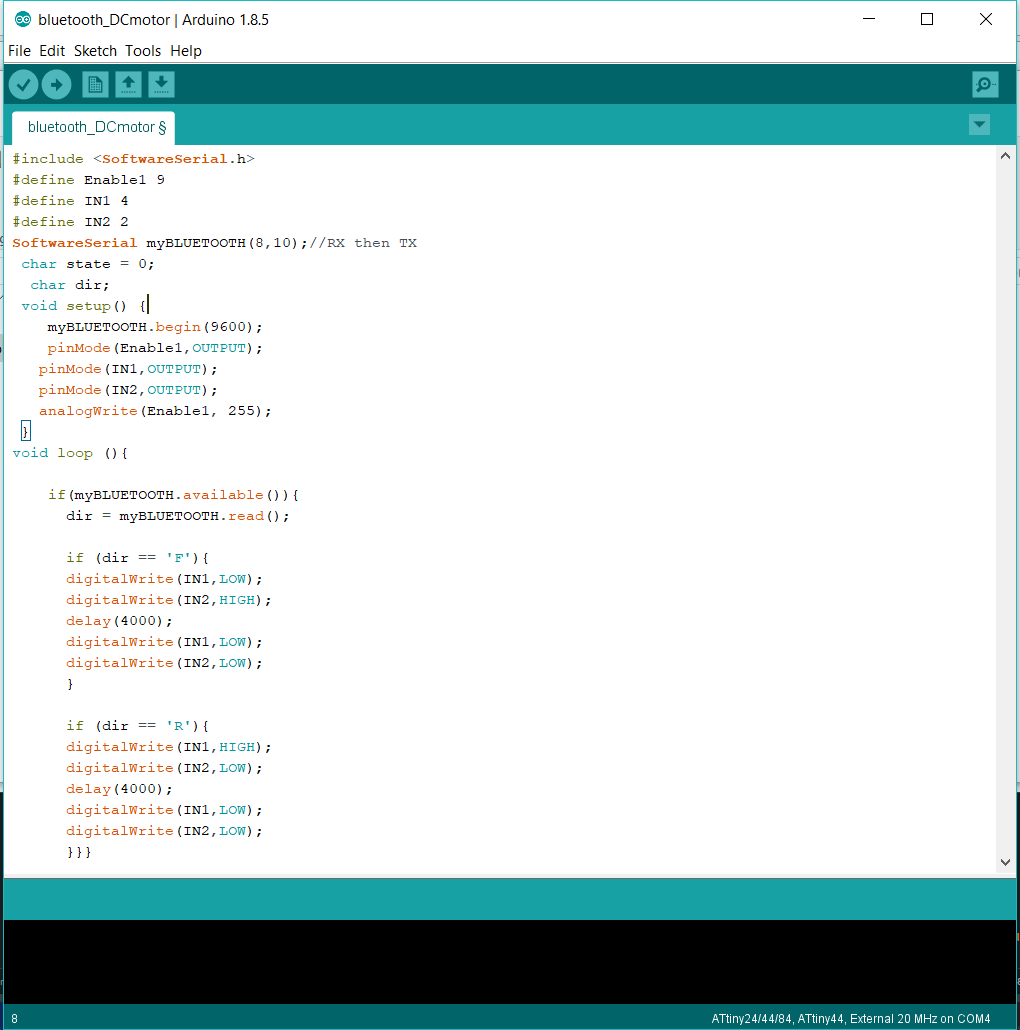
I controlled DC motor rotation direction using two buttons in output devices week. In this week I wnat to control motor rotation direction with bluetooth instead of buttons. This is my code:
Watch the results in this vedio:
As I mentioned before, I faced these problems with my designed board:
When I used a commerital Bluetooth module I noticed that it is easier to connect and control them at least I could do something useful with them.