TASKS :
Redraw the echo hello-world board, Add (at least) a button and LED (with current-limiting resistor)
Check the design rules, make it, and test it.
This week, we are going to design our own board, this is my fist experience to design a board.
The software which I will be using for this assignment is EAGLE
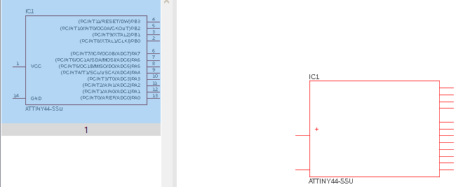
I start using this software by chose New Schematic
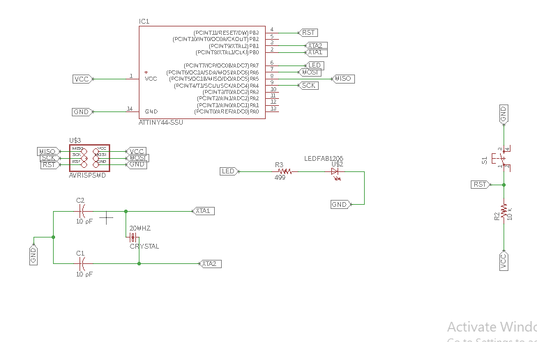
The schematic window is a collection of red circuit symbols which are interconnected with green nets.
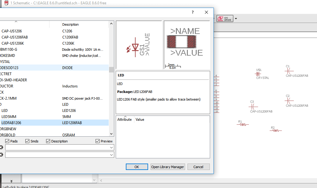
I download Fab library, the libraries store parts, which are combination of schematic symbol and PCB footprint.
After downloading the fab library I can add component by type "add" or select the "add icon from the toolbar".
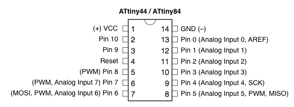
I will add microcontroller ATtiny44
I will use this chip to make my PCB. After reading the data sheet of ATtiny44 microcontroller, I know which component I will add.
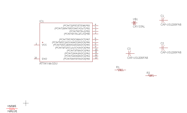
I add these components from the library:
These parts aolready on the Hello Echo Board
Microcontroller: Attiny44A. x1
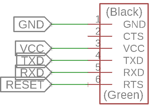
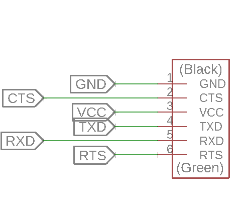
FTDI header x1 "powers the board and allows board to talk to computer"
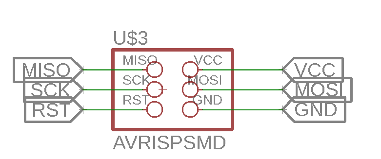
6-pin programming header "We use it for programming the board"
I will add : Crystal 20MHz x 1 Capacitor 10 pF x 2 Resistor 499 Ohm x 2 Resistor 10K Ohm x 1 LED x 2 SMD Buttons x1
To connect the components
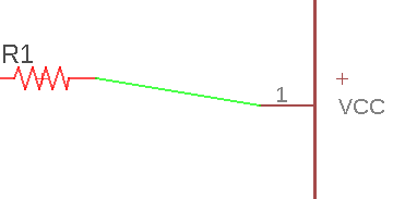
I can connect a components by chose Net command, when I chose it I can draw a green line green lines and connect the pins.
I can check the wire connection by chose a move and move the part, if it is connect the part will move with the wire.
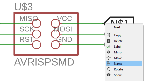
To connect the component, I name the nets which attached to the components by chose Labels
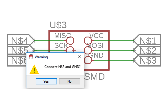
The parts will be connected by naming them with the same name.
I chose yes! So the part now will be connected.
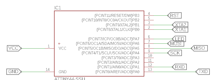
I connect the components with the Microcontroller by following the data sheet information.
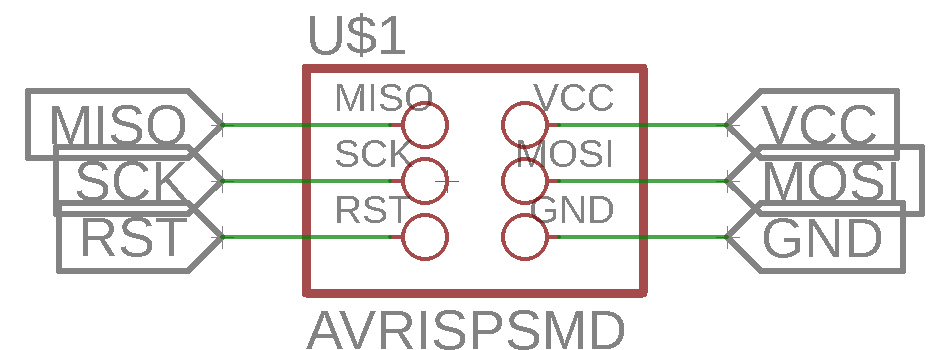
The AVRISPSDM and FTDI cable are connected with the Microcontroller.
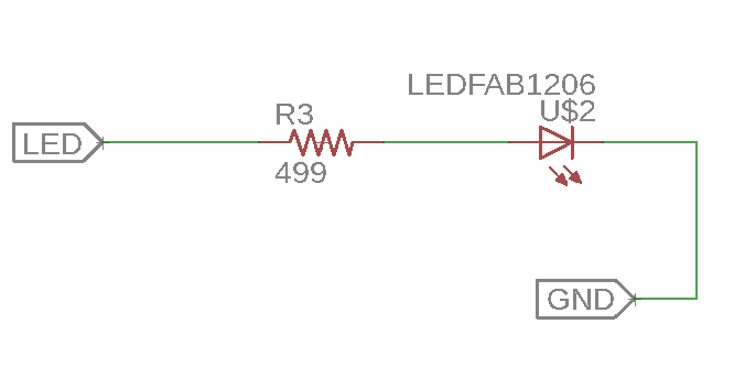
I placed two LEDs. One will be controlled by the SMD button, another by a digital pin called LED for both LEDs I chose 944 ohm resistor.
We can add the value for the resistor by click -right click- then chose the value and type the number.
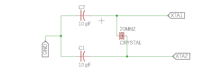
For crystal 20 Mhz I connect it with two capacitors 10 pF for both side, and connect it with the Microcontroller.
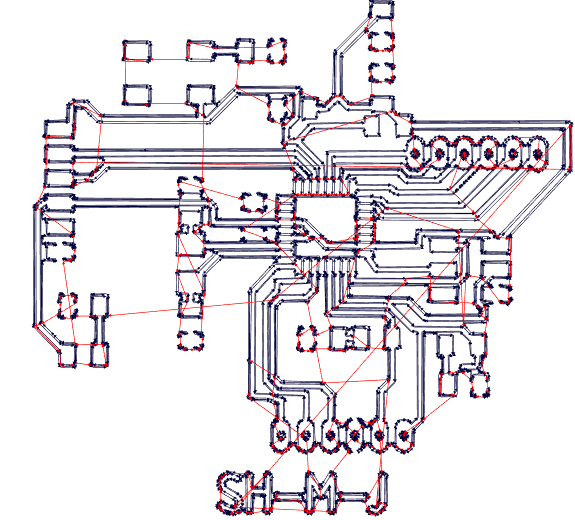
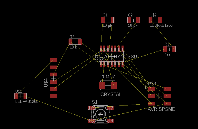
To see how the board layout look like, I press Generate/Switch to Board on the top menu.
The board editor is where the real magic happens.
Here colorful layers overlap and intersect to create a precisely measured PCB design.
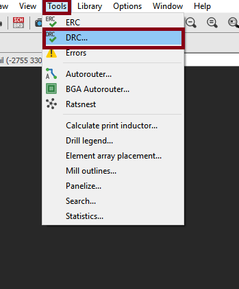
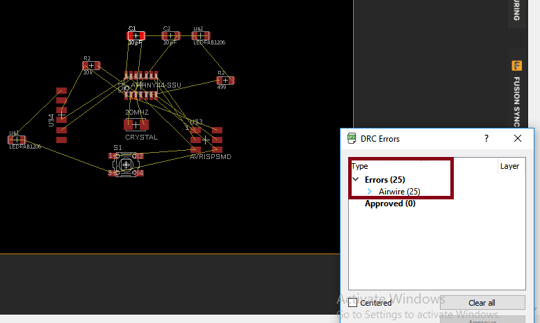
First I Download the DRCb to check that there is enough space everywhere.
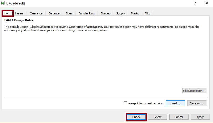
I saved the file as (.dru) then open from tool menu DRC then load.
After press check I can see that I have 25 errors
so let's work in the board and moving the components.
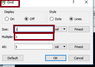
But before move the components I change the grid to 1mm
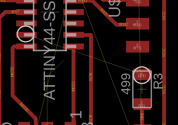
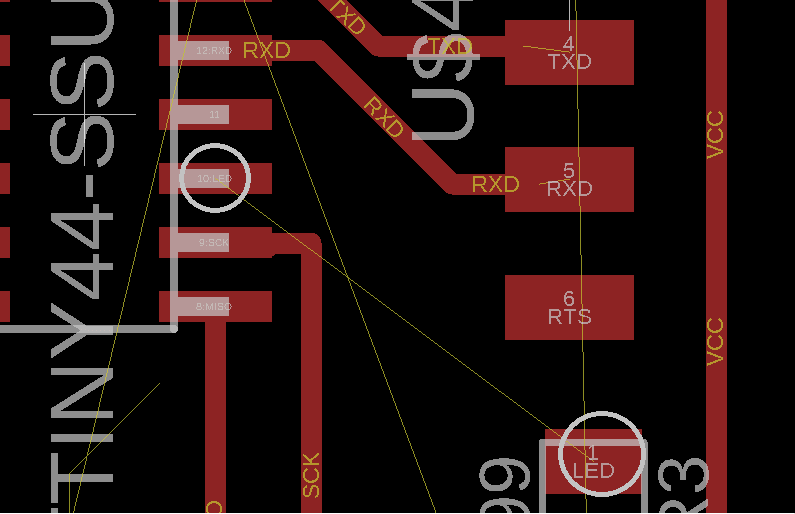
I have a problem with this LED connection!
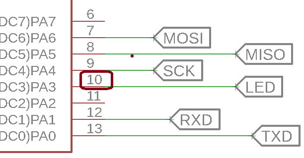
To fix this problem I go back to the Attiny44A data sheet and change the connection of LED.
I chose pin (10).
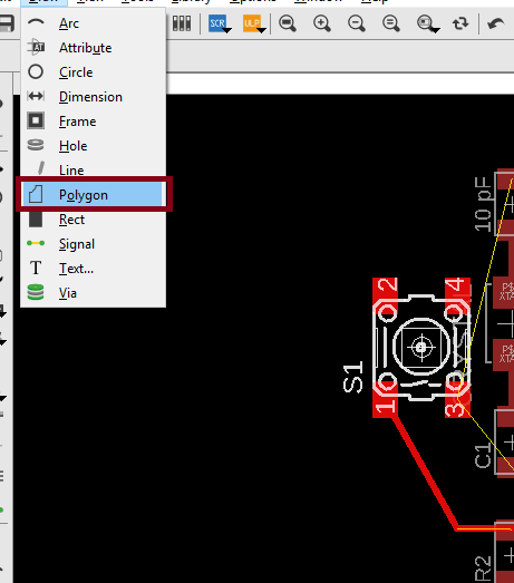
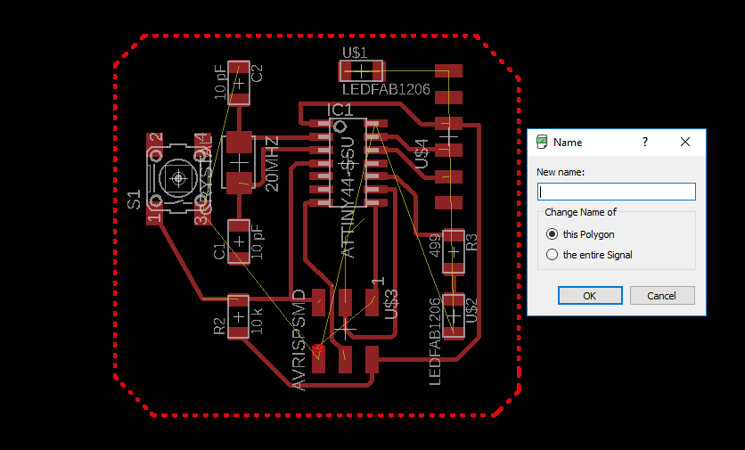
Then I draw a polygon around the components.
Then press right click on the polygon line, change the name on GND, the area inside the polygon will be filled.
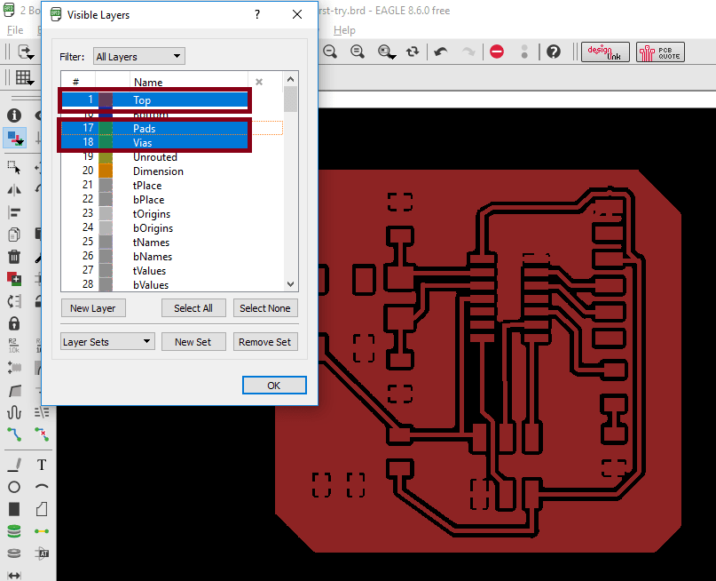
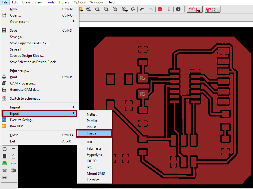
To prep board for milling:
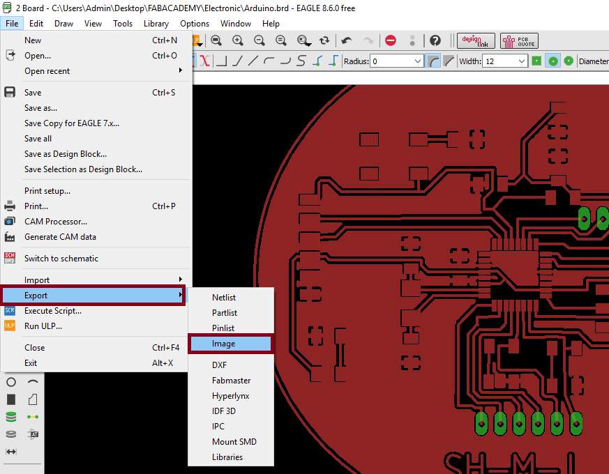
In layers menu in the top toolbar, select the only the top layer (traces only)
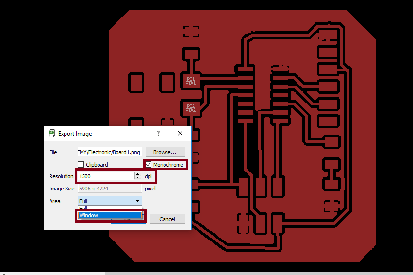
Then export the file as PNG file.
Settings should be MONOCHROME and 1500 DPI - this will export an image with white traces.
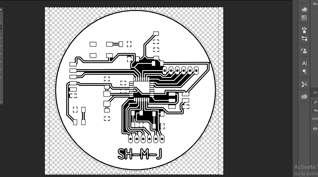
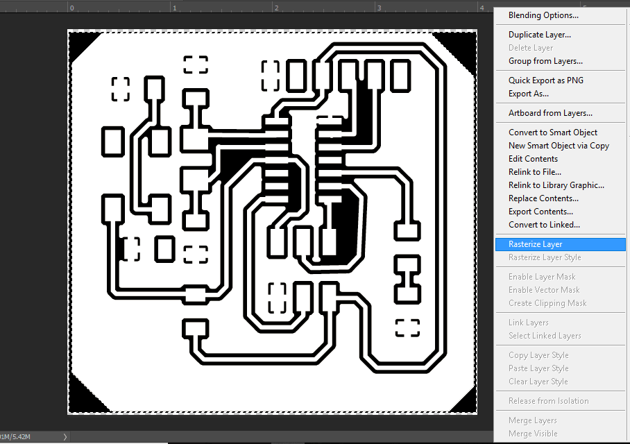
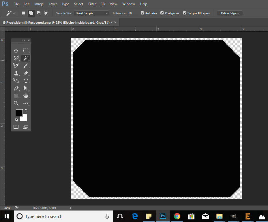
To edit the .PNG image, I will use PS. I should Rasterize the layer first, then by (magic tool)
I select the black color and change it to white.
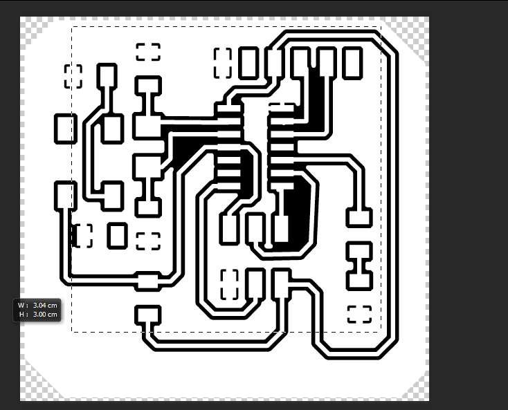
This will be the inside cut board. .
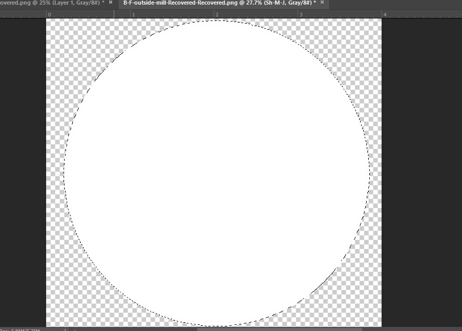
To make the outside cut I chose selection tool and fill it with black.
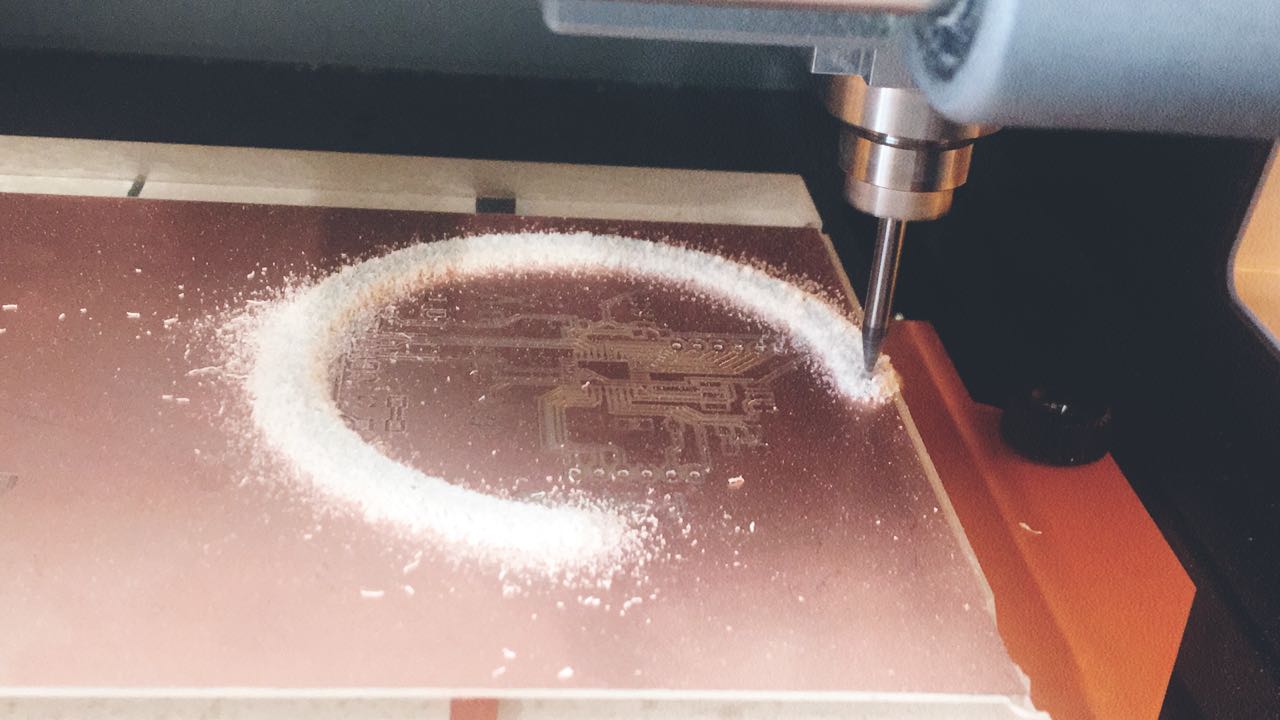
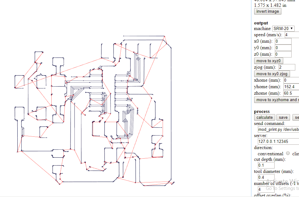
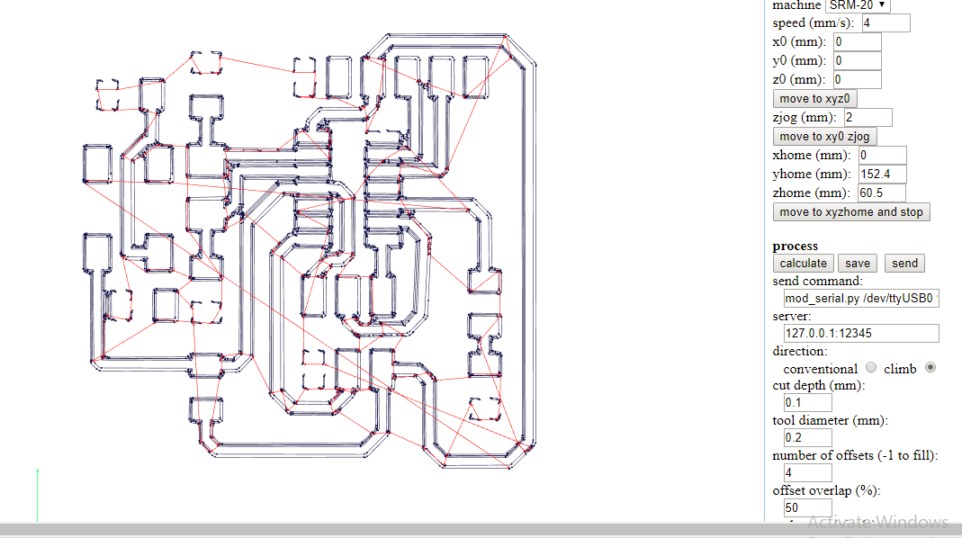
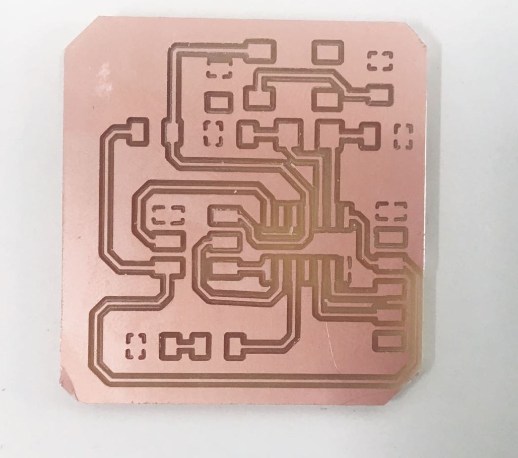
I used FabModules to convert the .PNG files into Gcodes for the Roland machine.
I input the png file and put the setting. I chose (0.4) tool diameter. Then I press calculate. .
I think it`s not good so I change the tool diameter to (0.2) mm. .
Now it`s better!
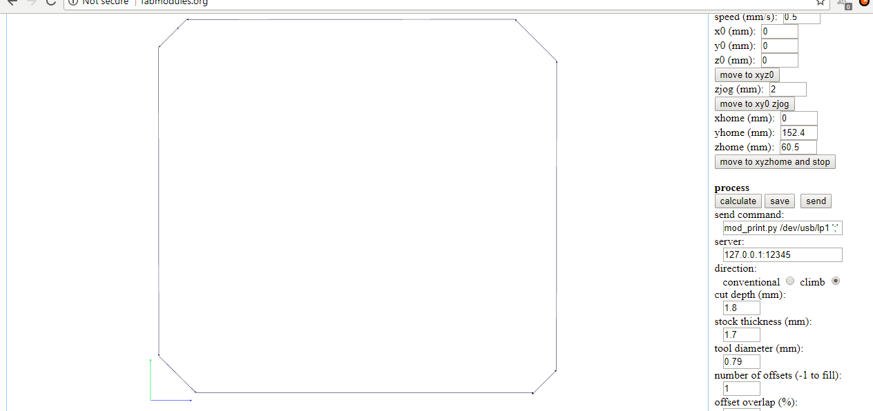
Then I input the outside cut.
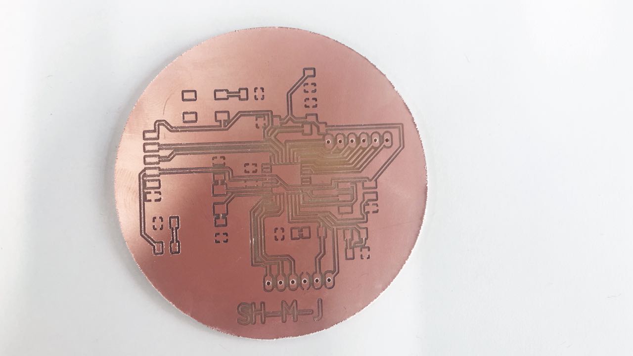
This is how the final result looks like:
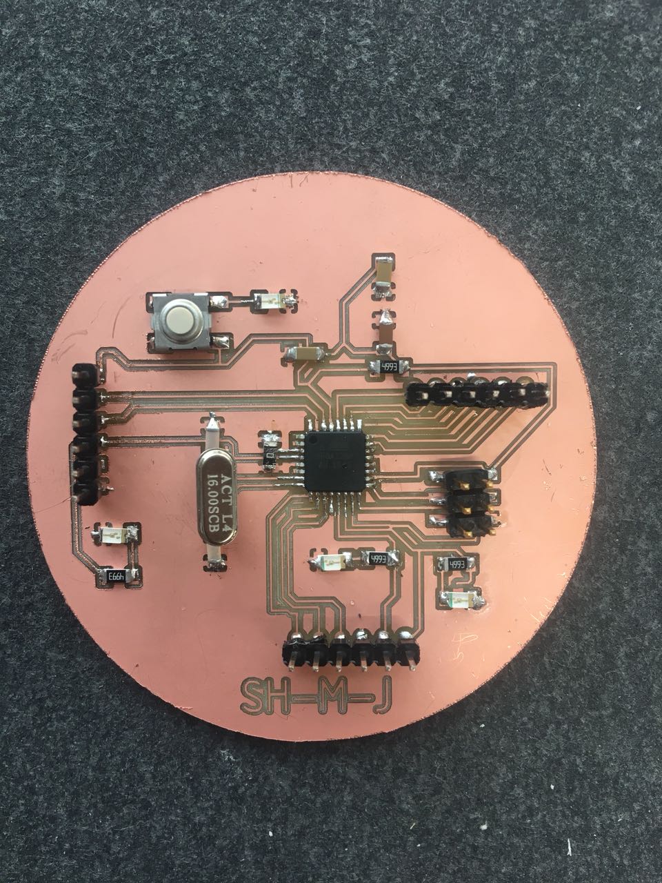
And now Let's solder it!
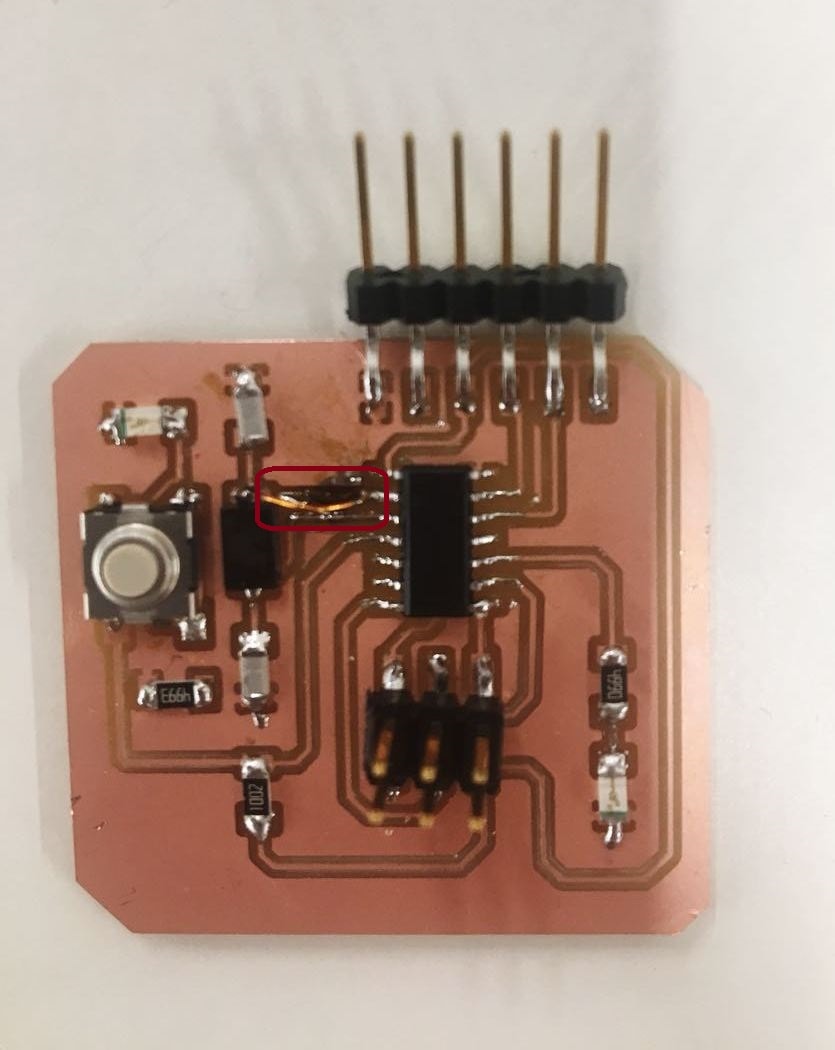
Problem
After I soldered all the components, I noticed that the crystal didn`t connect with the microcontroller, I decided to fix the problem rather than milling another PCB.
This is how I fixed it :
I used wire to conncet between the crystal and the microcontroller
Programing the board
I chose Arduino Arduinosoftware to program my board.
In the tools menu select the right board (Arduino Uno/Genuino)
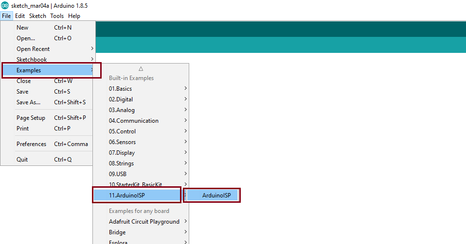
I need to make the Arduino as ISPto program the Echo-hello board
First, I connect the Arduino board to the USB hub, press on File .. Example select Arduino as ISP
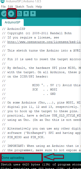
Upload the code
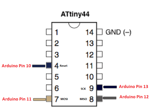
After the uploading is done, I connect the Arduino and my PCB with wires by following this picture.
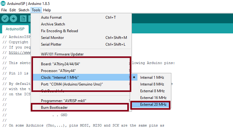
After the connection I go totool menu and chose the -Processor,Board and Clock- ATtiny24/44/84, ATtiny44, internal 20Mhz.
then press theBurn Bootloader button
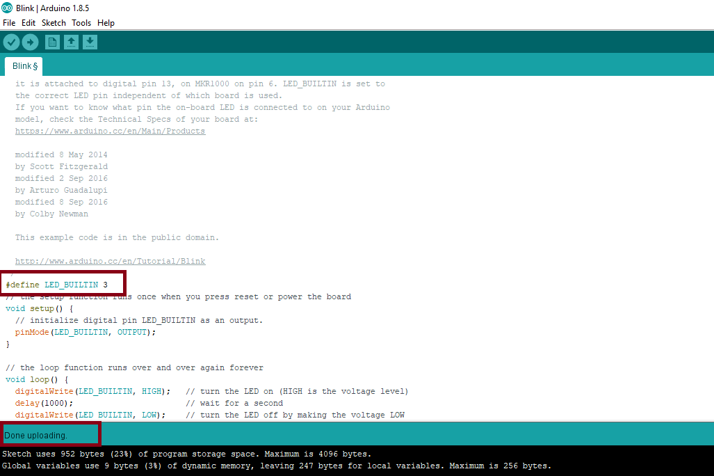
Then I chose the blink example to blink the LED in my board,and we have to define the right blink in my board I definePin 3 .
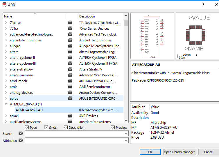
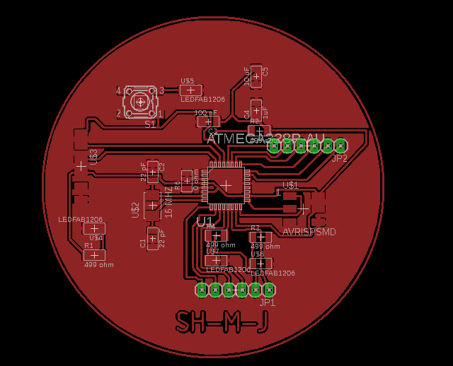
To design our own board, I chose ATmega328/P Following Daniele Ingrassia's Satshakit which is an improved and fabbable
ATmega328/P is a low-power CMOS 8-bit microcontroller
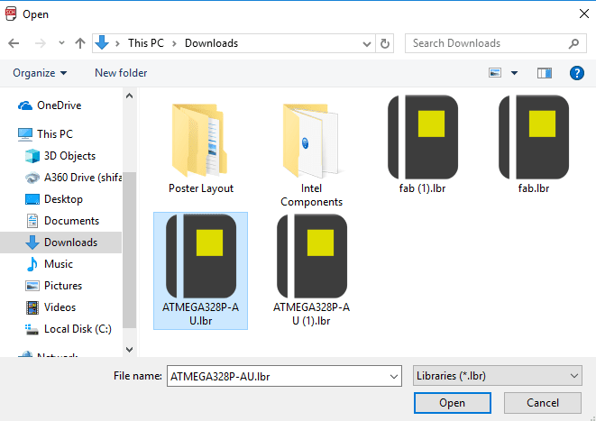
Downloaded the library of the component for eagle and I used Atmega328P.
I follow the data sheet to chose the components and connect them.
I add these components from Fab Library:
ATmega328/P x1
Capacitor 22 pF x2
Capacitor 1 uF x1
Capacitor 10 uF x1
Capacitor 100 nF x1
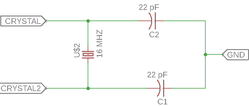
Crystal (16 MHz) x1
Resistor 499 ohm x4
SMD Buttons x 1
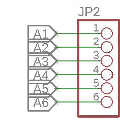
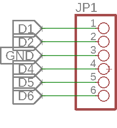
Pinhead x2v
FTDI header x1
AVRISPSMD x1
This is the circuit for the 16MHz crystal, reinforced from both sides with 22 pF capacitors, and connected using labels to the microcontroller.
I chose 2 pin headed one of them for Digital Pin connection, and the other for Analog connection
AVR_ISP pinheaders connect it with the microcontroller.
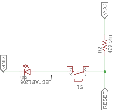
LED 1 : When I press the button, the LED is on, when I release the button, the LED is off.
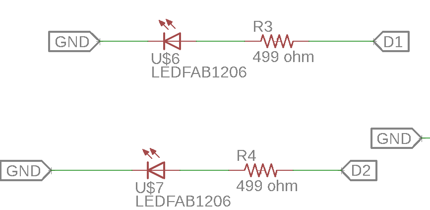
LED D1,D2 :I connect it with digital pin. When I send a signal to the digital pin HIGH, the LED will shine.
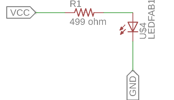
LED : this LED will work when the VCC and GND are connected it.
Connect the pins for the FTDI cable
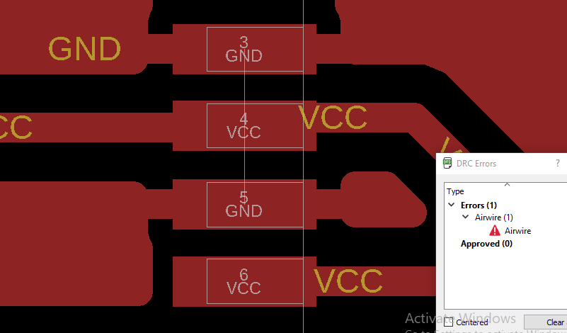
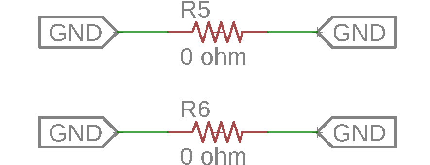
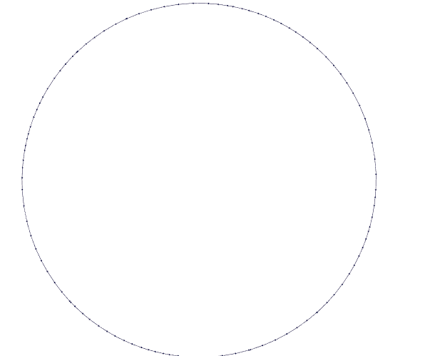
I draw a circle and name it (GND)
when I check my design athe GND that wasn't connected to solve this problem I add Resistor (0 ohm) and connect both side with GND.
Now I have no error in my file, I chose export to export the file as PNG file
Edit the PNG file Using PS- Photoshop software
I use
Fab modules to convert the png file to G-code
.png)