measure something: add a sensor to a microcontroller board that you have designed and read it.
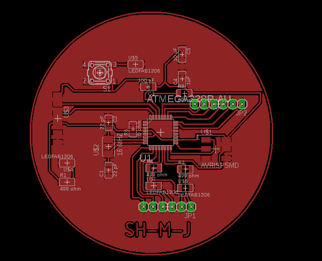
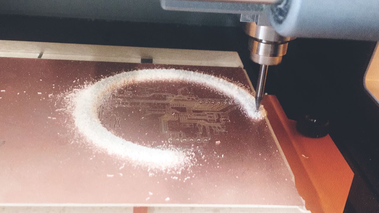
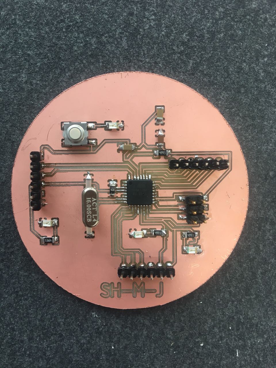
ARDUINO Board
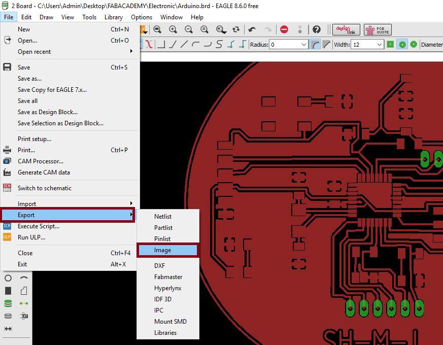
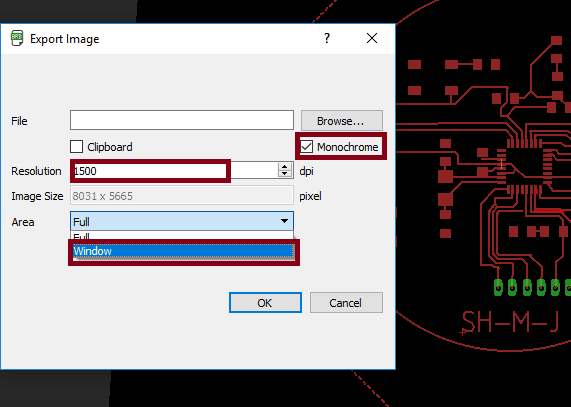
The software which I will be using for the Arduino design is EAGLE
I start using this software by chose New Schematic
The schematic window is a collection of red circuit symbols which are interconnected with green nets.
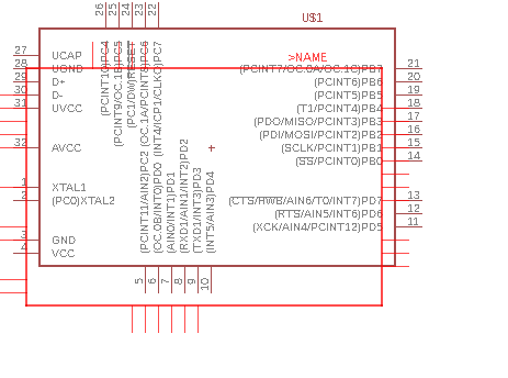
To design our own board, I chose ATmega328/P.
ATmega328/P is a low-power CMOS 8-bit microcontroller
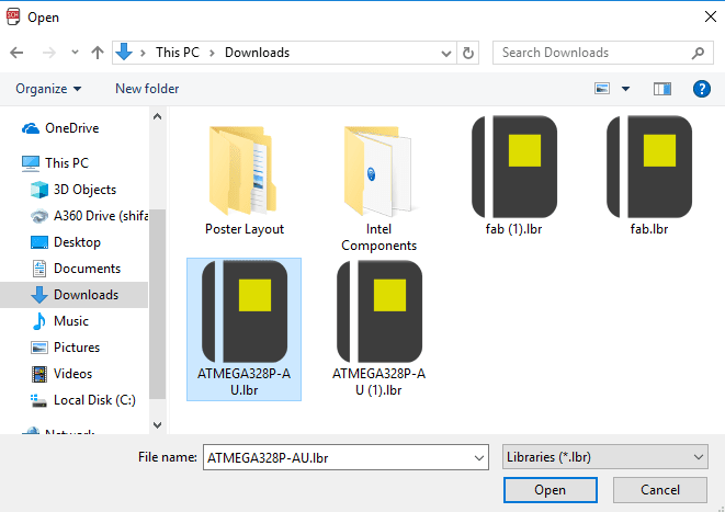
I download a library (ATmega328/P) library. Then I add the component on schematic window.
I follow the data sheet to chose the components and connect them.
I add these components from Fab Library:
ATmega328/P x1
Capacitor 22 uF x2
Capacitor 1 uF x1
Capacitor 10 uF x1
Capacitor 100 nF x1
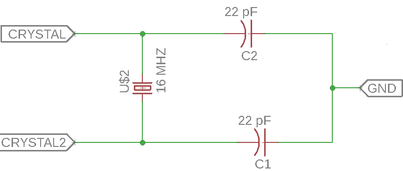
Crystal (16 MHz) x1
Resistor 499 ohm x4
SMD Buttons x 1
Pinhead x2v
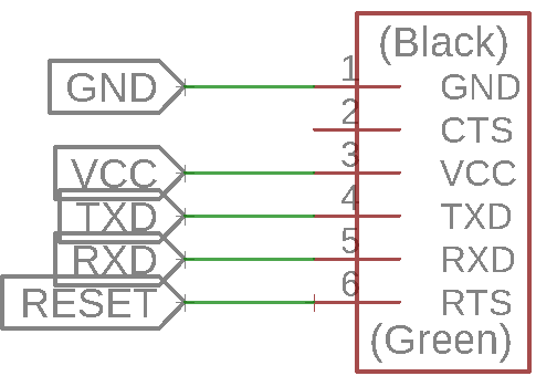
FTDI header x1
AVRISPSMD x1
This is the circuit for the 16MHz crystal, reinforced from both sides with 22pF capacitors, and connected using labels to the microcontroller.
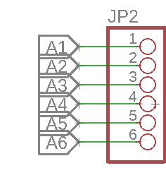
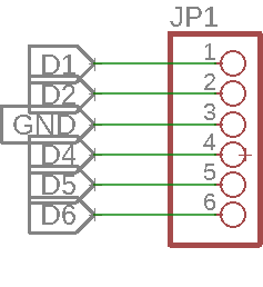
I chose 2 pinheaded one of them for (Digital Pin) connection, and the other for ( Analoge) connection
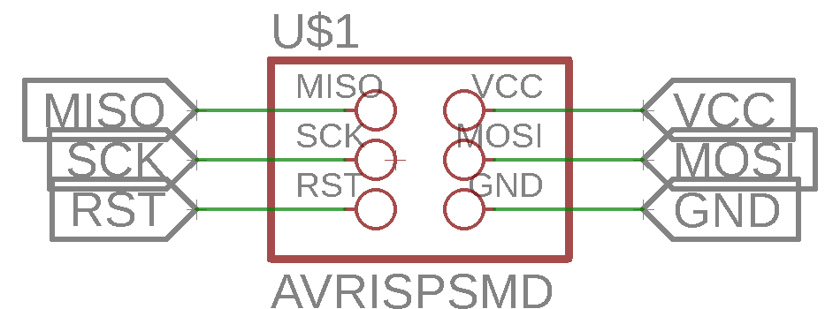
AVR_ISP pinheaders connect it with the microcontroller.
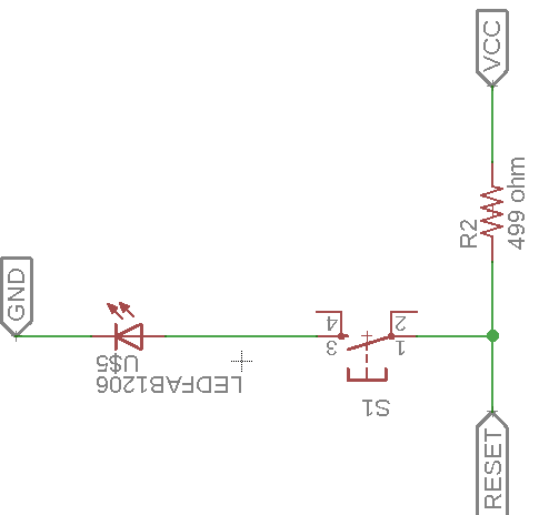
LED 1 : When I press the button, the LED is on, when I release the button, the LED is off.
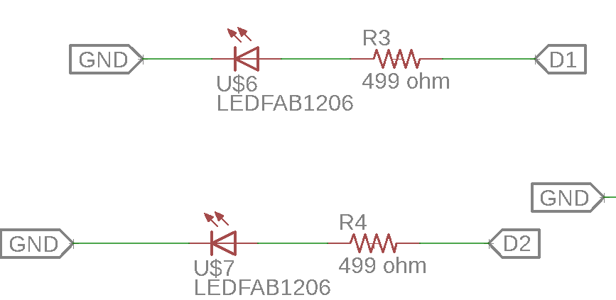
LED D1,D2 :I connect it with digital pin. When I send a signal to the digital pin HIGH, the LED will shine.
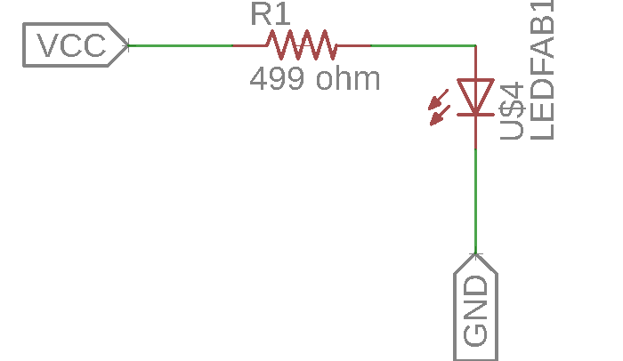
LED : this LED will work when the VCC and GND are connected it.
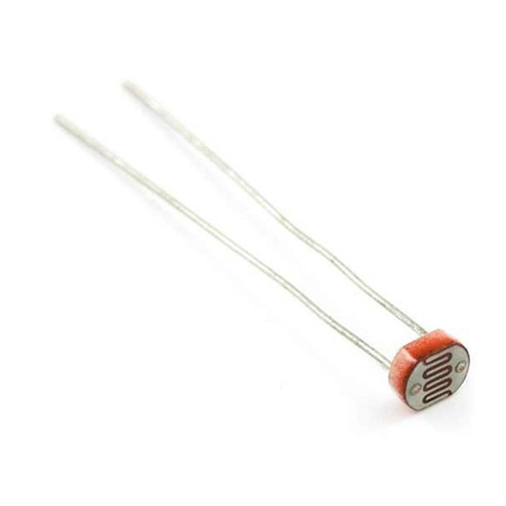
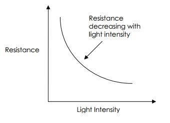
LDR " The LDR is a special type of resistor that allows higher voltages to pass through it (low resistance) whenever there is a high intensity of light, and passes a low voltage (high resistance) whenever it is dark."
How does it work ?
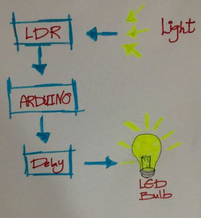
It`s a sensor that can be used to detect light.When the light level decreases, the resistance of the LDR increases . As this resistance increases in relation to the other Resistor, which has a fixed resistance, it causes the voltage dropped across the LDR to also increase
Testing the Code for the Arduino LDR Sensor
I write this Code then i test it with arduino :
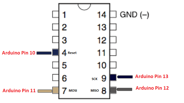
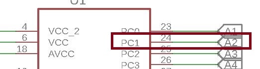
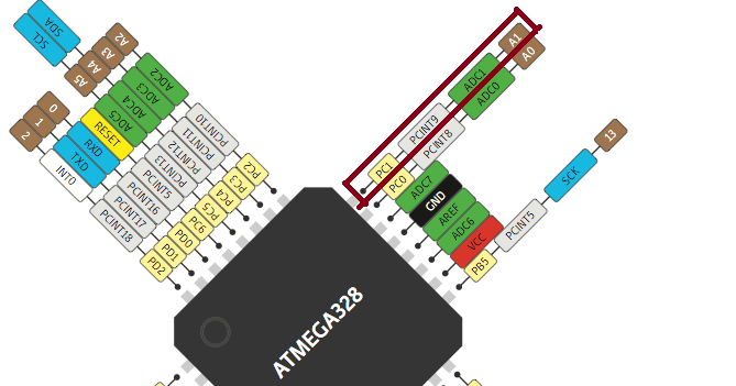
Chose analoge A2 PC1 :
By following the data sheet PC1 = Arduino Pin is A1
  int ledPin = 6;

void setup() {
pinMode(ledPin, OUTPUT);

Serial.begin(9600);
}

void loop() {

int photocell = (analogRead(A1)/4); // Divides input 0-1023 to resemble to 0-255


Serial.println(photocell);
if (photocell>300)
  digitalWrite (ledPin,1);


if (photocell<300)
  digitalWrite(ledPin,0);


delay(200);

}
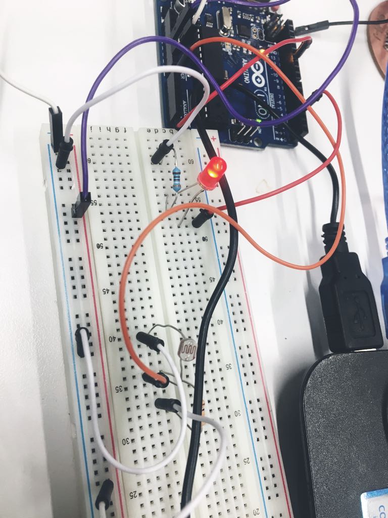
Connect the LDR with Arduino:
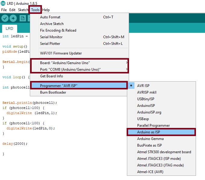
Now ! To program my board I use Arduino as ISP Arduino will be the programmer to my board.
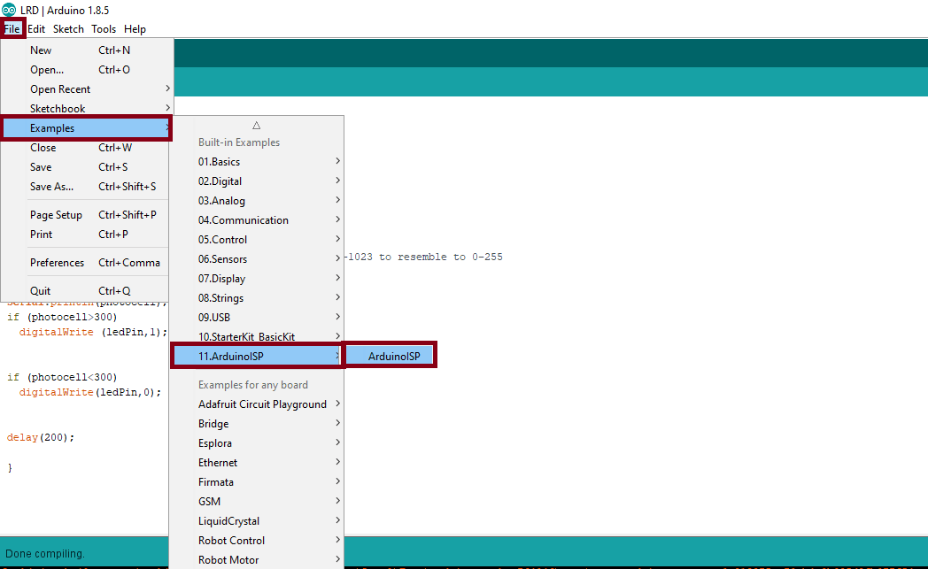
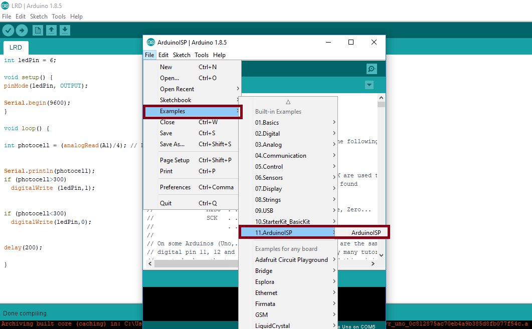
First from File menu I chose Example then Arduino ISP
After the uploading, I connect my board with Arduino to complete the programming.
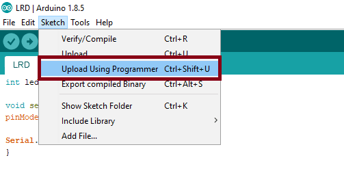
After I check the connection, from tool menu :
then from Sketch menu
Done Uploading ! let`s see the result :
But there is a problem with delay
Ultrasonic Sensor
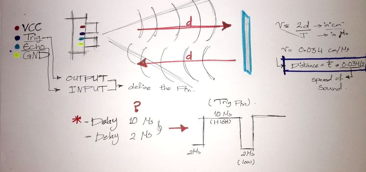
Ultrasonic sensors measure distance by using ultrasonic waves.
The sensor head emits an ultrasonic wave and receives the wave reflected back from the target. Ultrasonic Sensors measure the distance to the target by measuring the time between the emission and reception.
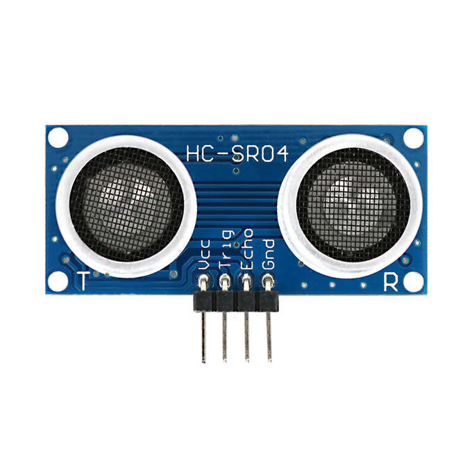
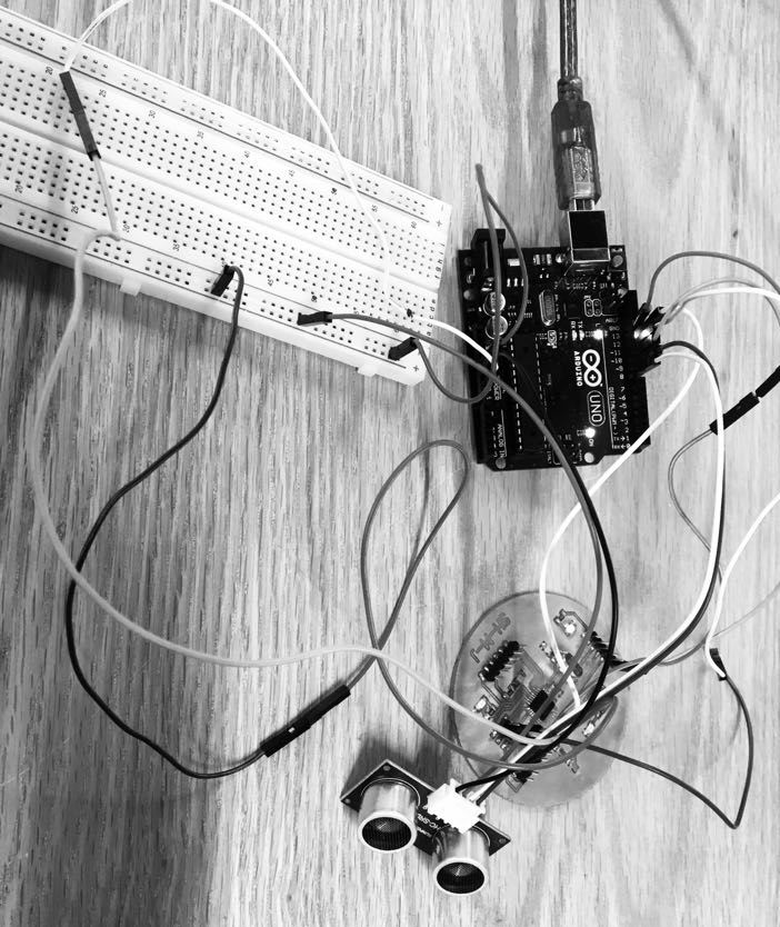
The Ultrasonic Module has 4 pins: Ground, VCC, Trig and Echo
Th Ground and the VCC pins needs to be connected to the Ground and the 5 volts pins on the Arduino Board
The trig and echo pins to any Digital pin on the Arduino Board.
Before writing the code I need to understand How does the Ultrasonic Sensor work?
To test the code, First I upload it to Arduino.
Connect the VCC of Ultrasonic Sensor... with the VCC of Arduino
Connect the GND of Ultrasonic Sensor... with the GND of Arduino
Connect Trig of Ultrasonic Sensor .. with Pin 5 in Arduino
Connect Echo of Ultrasonic Sensor .. with Pin 6 in Arduino
And this is the code:
//Define Arduino Pin
int trigPin =5;
int echoPin =6;
#define LED 7
//Define variables
long duration;
int distance;
void setup() {
// put your setup code here, to run once:
pinMode( trigPin , 1); //trigpin is output
pinMode(echoPin , 0); //echo pin is input
Serial.begin (9600); //Start serial communication
}
void loop() {
digitalWrite(trigPin, LOW);
delayMicroseconds(2);
// Sets the trigPin on HIGH state for 10 micro seconds
digitalWrite(trigPin, HIGH);
delayMicroseconds(10);
digitalWrite(trigPin, LOW);
// Reads the echoPin, returns the sound wave travel time in microseconds
duration = pulseIn(echoPin, HIGH);
// Calculating the distance divided by 2
distance= duration*0.034/2;
}
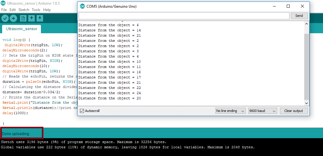
// Prints the distance on the Serial Monitor
Serial.print("Distance from the object = ");
Serial.println(distance);//print new line
delay(1000);
}
The result will be printed in serial Monitor.
Now let`s go to program it in my board using Arduino as ISP
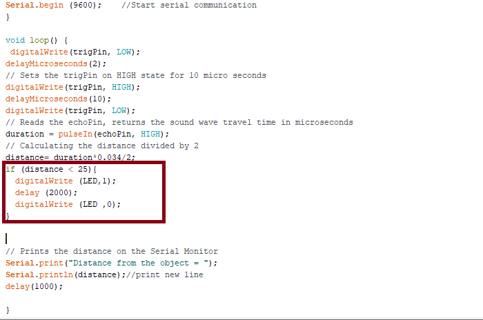
Connect my board with Arduino, like what I did before with LDR sensor But the problem is I don`t have Serial Monitor in my borad so I Write this code
to test the Ultrasonic Sensor
So if the Ultrasonic Sensor read the distance less than 25 cm the LED will blink.
The LED is working:)
But I have the same problem with Delay !!
To fix the problem
I change the Crystal and yes finally it works !:)
.png)


-min.png)