Tasks:
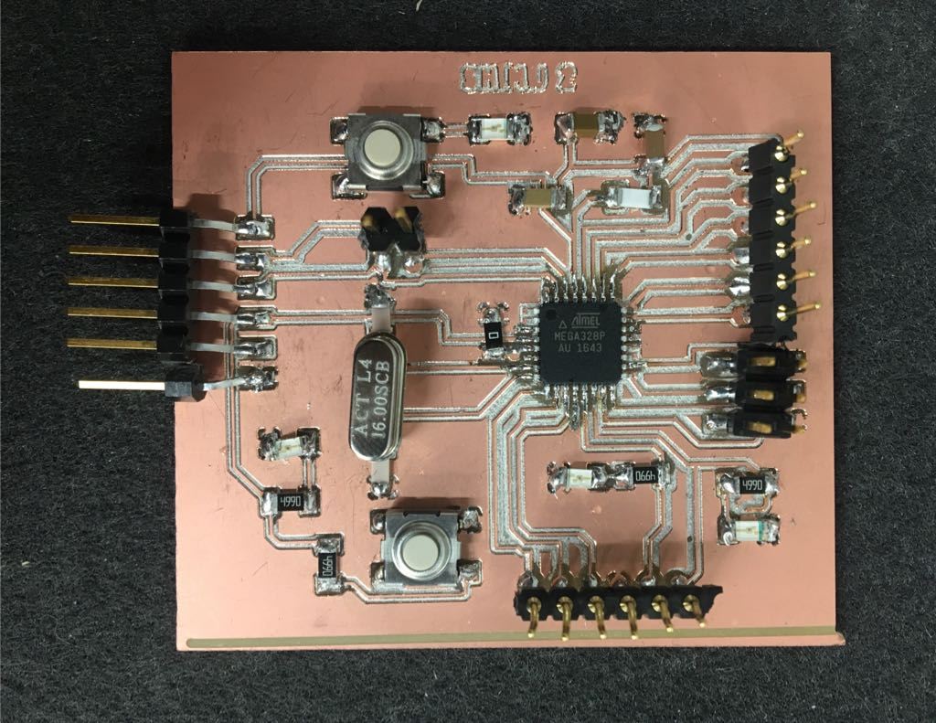
Write an application that interfaces with an input and/or output device
that you made
    void setup() {

  pinMode(10, OUTPUT);   //set pin as output , Red led
  pinMode(9, OUTPUT);   //set pin as output , White led
  pinMode(7, OUTPUT);   //set pin as output , Blue led
  pinMode(6, OUTPUT);  //set pin as output , Green led
  pinMode(5, OUTPUT); // set pin as output , yellow led

  Serial.begin(9600);    //start serial communication @9600 bps
  }

void loop(){

  if(Serial.available()){  //id data is available to read

    char val = Serial.read();

    if(val == 'r'){       //if r received
      digitalWrite(10, HIGH); //turn on red led
      }
    if(val == 'b'){       //if b received
      digitalWrite(9 , HIGH); //turn on blue led
      }
    if(val == 'w'){       //if y received
      digitalWrite(7 , HIGH); //turn on white led
      }
      if(val == 'g') {
        digitalWrite(6 , HIGH); // turn on green led
      }
      if(val == 'y'){
        digitalWrite(5, HIGH); // turn on yellow led
      }
    if(val == 'f'){       //if f received
      digitalWrite(10, LOW); //turn off all led
      digitalWrite(9, LOW);
      digitalWrite(7, LOW);
      digitalWrite(6, LOW);
      digitalWrite(5, LOW);

      }
    }
  }
stop blinking.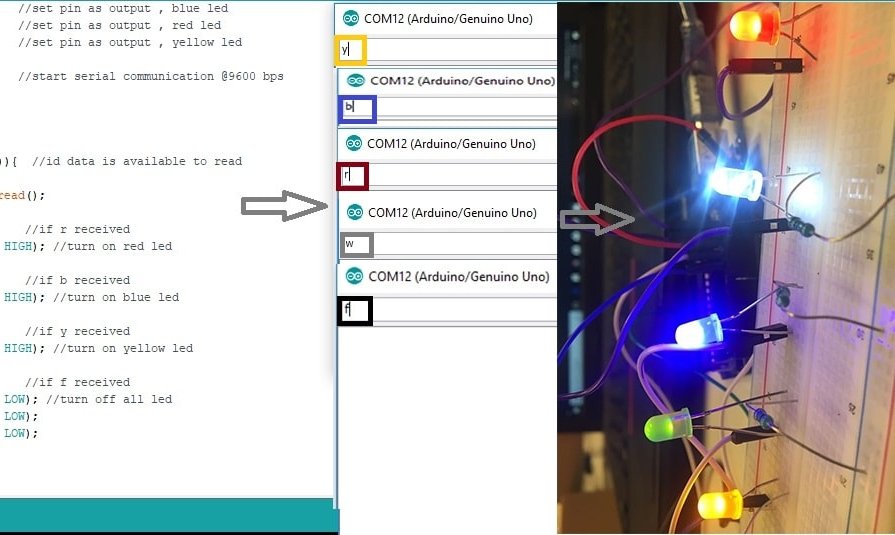
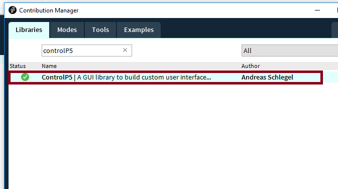
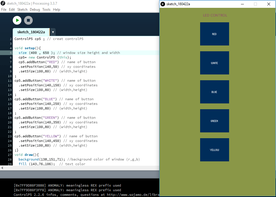
GUI (graphical user interface) with which you can do many things.sketch menu to import (Control P5) library. 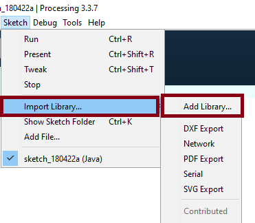
import controlP5.*; // import controlP5
import processing.serial.*;
Serial port;
ControlP5 cp5 ; // creat controlP5
PFont font;
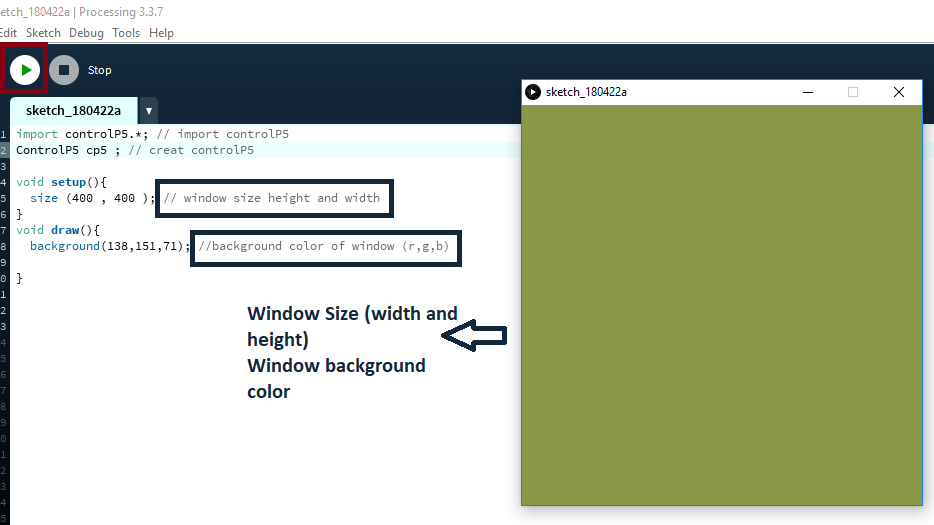
void setup(){
size (400 , 650 ); // window size height and width
printArray (Serial.list()); //prints all available serial ports
port = new Serial (this,"COM12",9600);
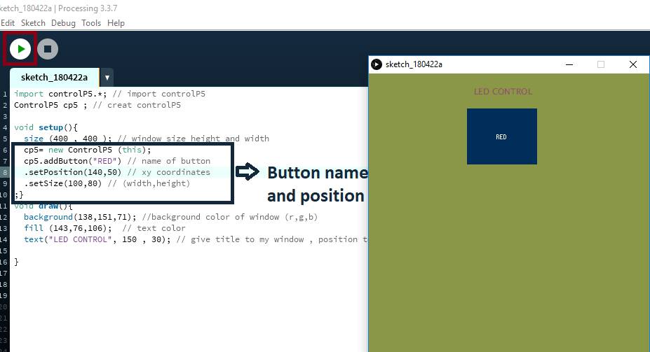
cp5= new ControlP5 (this);
cp5.addButton("red") // name of button
.setPosition(140,50) // xy coordinates
.setSize(100,80) // (width,height)
;
cp5.addButton("white") // name of button
.setPosition(140,150) // xy coordinates
.setSize(100,80) // (width,height)
;
cp5.addButton("blue") // name of button
.setPosition(140,250) // xy coordinates
.setSize(100,80) // (width,height)
;
cp5.addButton("green") // name of button
.setPosition(140,350) // xy coordinates
.setSize(100,80) // (width,height)
;
cp5.addButton("yellow") // name of button
.setPosition(140,450) // xy coordinates
.setSize(100,80) // (width,height)
;
cp5.addButton("alloff") // all led will be on
.setPosition(140,550) // xy coordinates
.setSize(100,80); // (width,height)
}
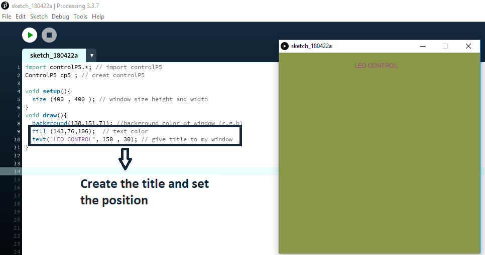
void draw(){
background(138,151,71); //background color of window (r,g,b)
fill (143,76,106); // text color
text("LED CONTROL", 150 , 30); // give title to my window , position to the title
}
void red(){
port.write ('r');
}
void white(){
port.write('w');
}
void blue(){
port.write('b');
}
void green(){
port.write('g');
}
void yellow(){
port.write ('y');}
void alloff(){
port.write('f');}
what has been received will light 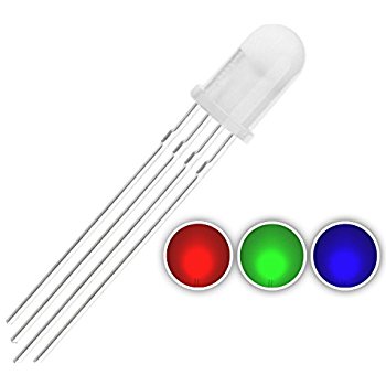
import serial #import serial to enable sending and receiving data using the serial port
import tkinter #tkinter is the GUI for python
data= serial.Serial('com15','9600') #define the com of the arduino and the baud rate which is set to 9600
def turn_red_on(): #This is to turn the LED on, we send one over the serial port and in the arduino code we turn the led on using digitalWrite
 data.write(b'0')
def turn_blue_on(): #This is to turn the LED off, we send one over the serial port and in the arduino code we turn the led off using digitalWrite
 data.write(b'1')
def turn_green_on():
 data.write(b'2')


def turn_white_on():
    data.write(b'3')
led_ctrl_win=tkinter.Tk()
Button=tkinter.Button
text=tkinter.Text
Red=Button(led_ctrl_win, text=" RED ", command=turn_red_on,  height=6, width=10)
Blue=Button(led_ctrl_win, text="BLUE ", command=turn_blue_on,height=6, width=10)
Green=Button(led_ctrl_win, text="Green", command=turn_green_on,height=6, width=10)
white=Button(led_ctrl_win, text="White", command=turn_white_on,height=6, width=10)
#T= text(led_ctrl_win, height=2, width=30)
#T.insert(data.read())
Red.pack(side=tkinter.LEFT)
Green.pack(side=tkinter.LEFT)
Blue.pack(side=tkinter.LEFT)

white.pack(side=tkinter.RIGHT)

led_ctrl_win.mainloop()
#define red 10
#define blue 7
#define green 9
void setup() {
  // put your setup code here, to run once:
Serial.begin(9600);
pinMode(red,OUTPUT);
pinMode(blue, OUTPUT);
pinMode(green, OUTPUT);
}

void loop() {
  // put your main code here, to run repeatedly:

          int data=Serial.read();
          switch (data){
          case '0':
               setColor(0, 255, 255); // Red Color
                break;

           case '1':
               setColor(255, 255, 0); // Blue Color
                break;

          case '2':
               setColor(255, 0, 255); // Green Color
                break;

           case '3':
           setColor(0, 0, 0); // White Color
                break;


}

}
void setColor(int redValue, int greenValue, int blueValue) {
  analogWrite(red, redValue);
  analogWrite(green, greenValue);
  analogWrite(blue, blueValue);
}
I don`t face any problem in this assignment :)