Computer-controlled cutting
Computer-controlled cutting
Our task is :
- To cut something that we designed, using a vinyl cutter.
- Testing the kerf and cutting setting,(group assignment.)
- Design something using parametric program and cut it on the lazaer cutter.
Vinyl Cutter
I decided to use Inkscape program which work in victor, I drew a sketch so I can easily design it in this program.
Starting with a circle then drawing a pointer by Straight line tool .
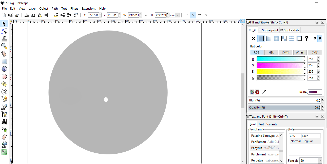
-min.png)
Write a text by text tool I can easily change the dimension and font size.
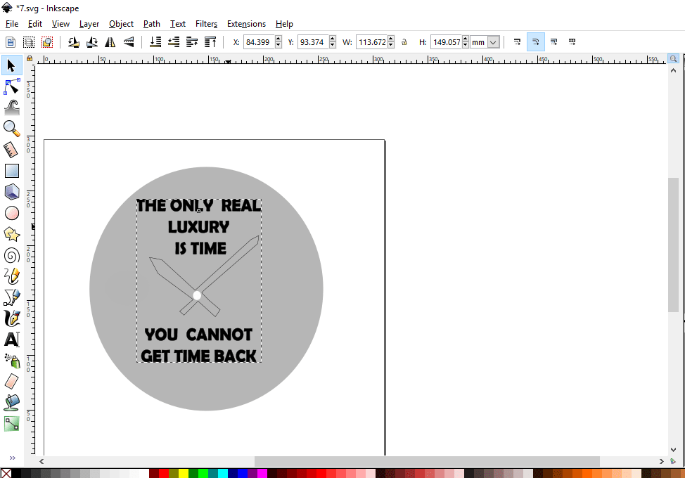
The font size is 43 and the font family is Berlin San FB Demi
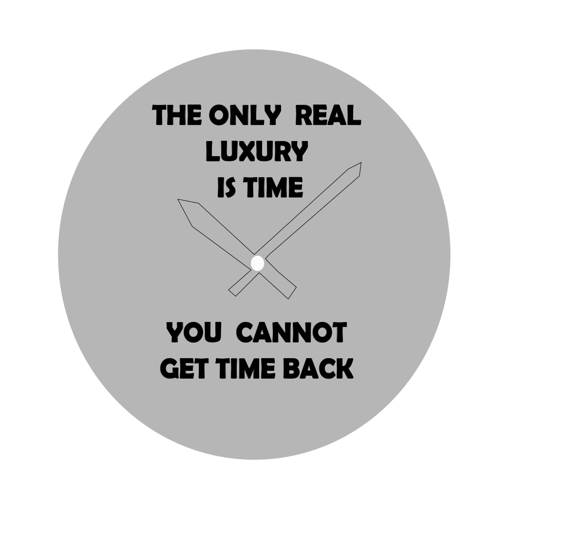
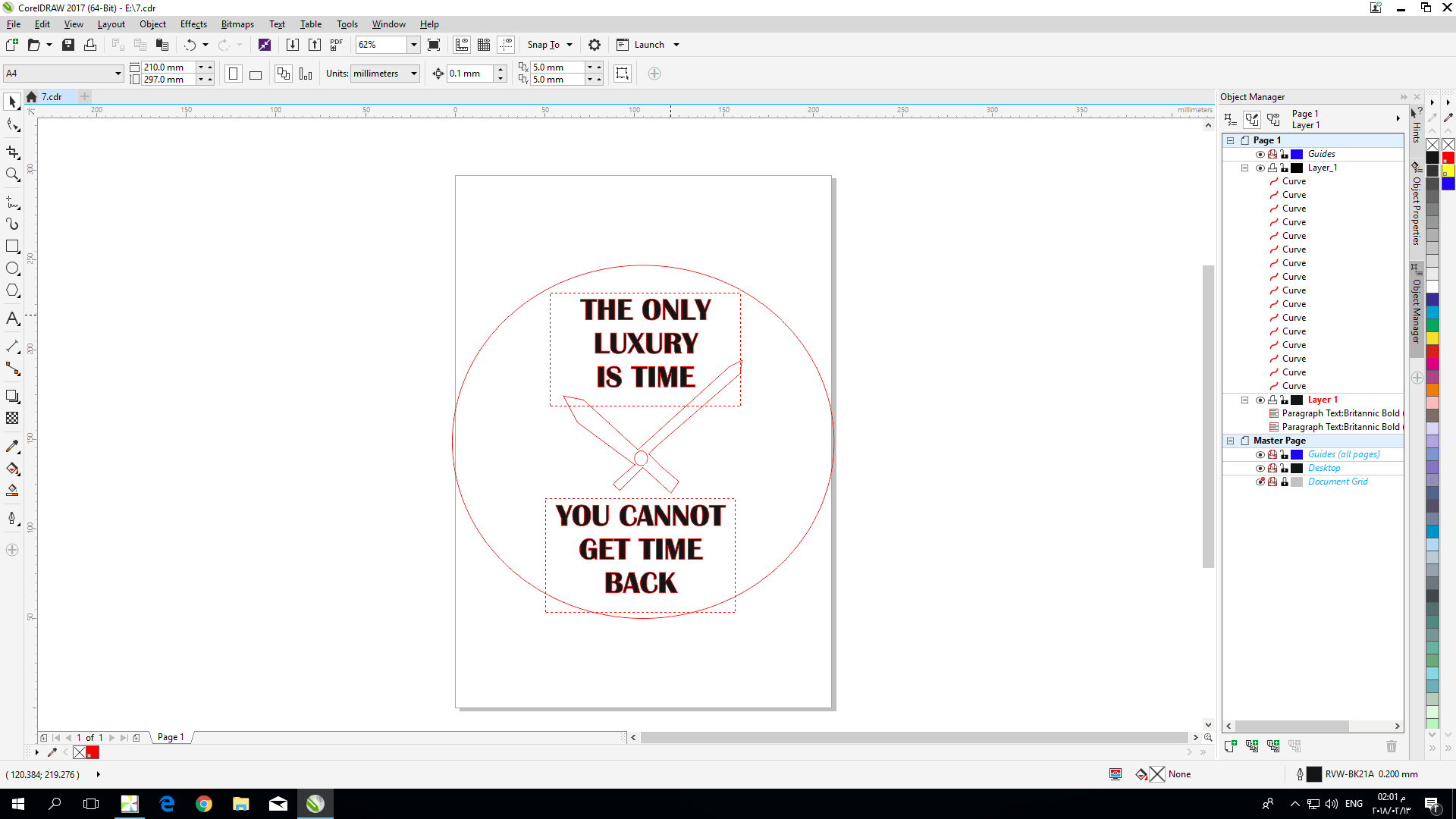
This is how the final design look like !
The next step is to import my design to the Corel draw Corel draw software.
The problem was when I open it, the text of my logo doesn’t appear so I rewrite it using the text tool of Corel draw
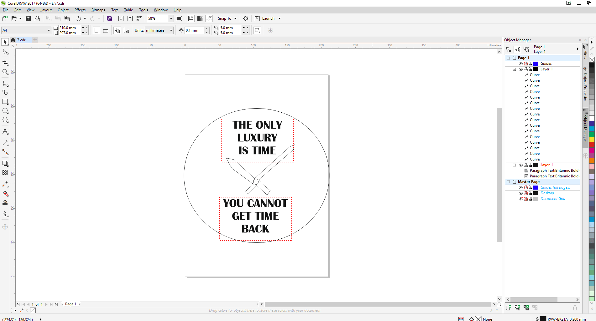
Then select the logo and change the color to Red 255 RGB, now the printer will read the cut line .
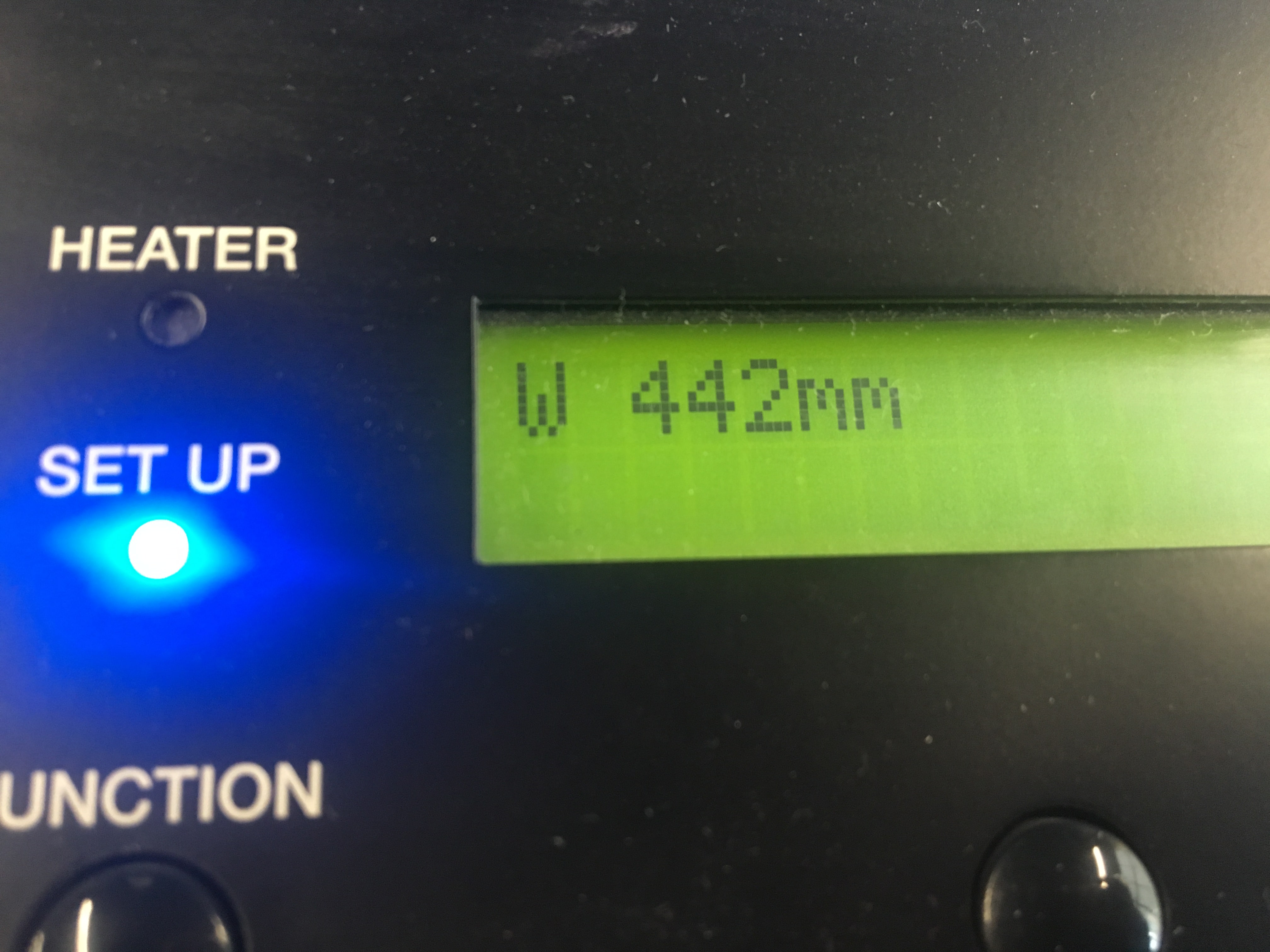
In Roland software I Imported my design, but before that I checked the width of the material
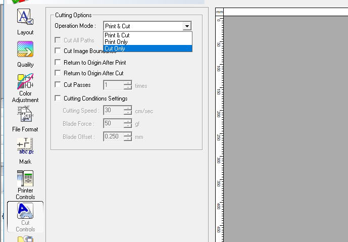
Set the settings of the software :
operation mode cut only
Blade force is 80 gf
press cut is 3 times, so I can easily remove the cut line.
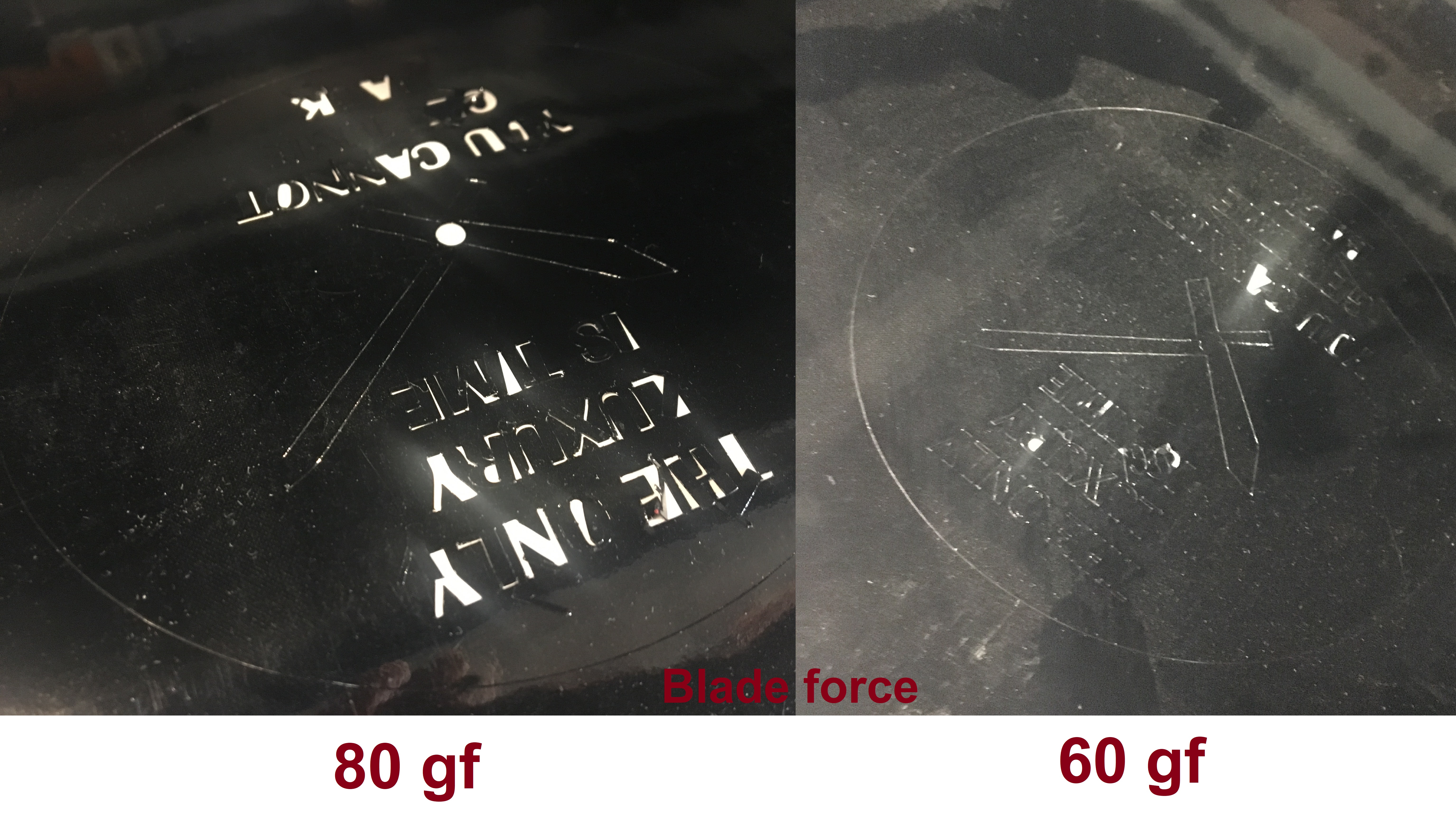
Problem :
The blade force was big ! so I change it to 60 gf
This image shows the difference between them: :
Finally, this is how it looks after I removed everything.
Laser cutting
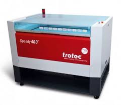
The Laser Cutter that we are using in our lab is trotec speedy 400, the interface program is Jobcontrol
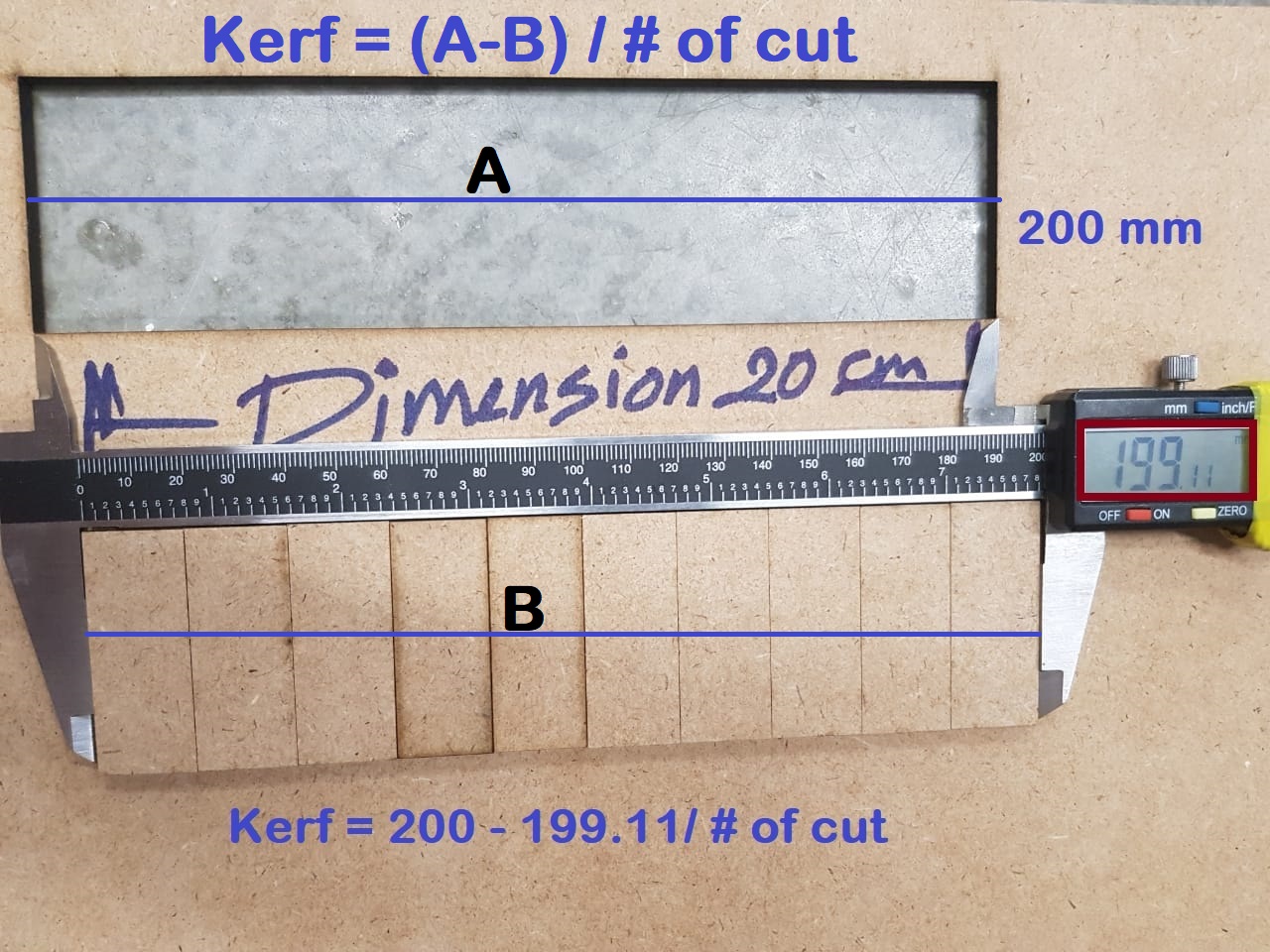
Starting with the kerf assignment
kerf The laser burns away a portion of material when it cuts through. This is known as the laser kerf and ranges from 0.08mm – 1mm.
Depending on the material type and other conditional factor.
I chose to test the kerf for Plywood, thickness 4.00 mm .
This is my kerf file, I draw it using AutoCAD software.
-min.png)
Best sitting for Plywood 4.00 mm thickness is :
Power = 100%
Frequency = 50000
speed = 0.35
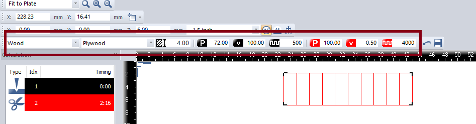
The kerf is 0.04.
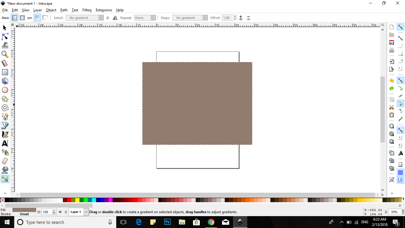
So after the kerf assignment I tried to make a cover for my note book, design it by Inkscape.
Measuring the dimension of my notebook then draw a rectangle in Inkscape program and put the dimension 280 , 210 mm.
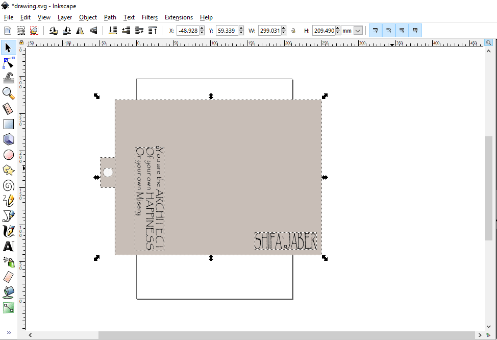
Using text tool to write the text, for front side and back side in my cover.
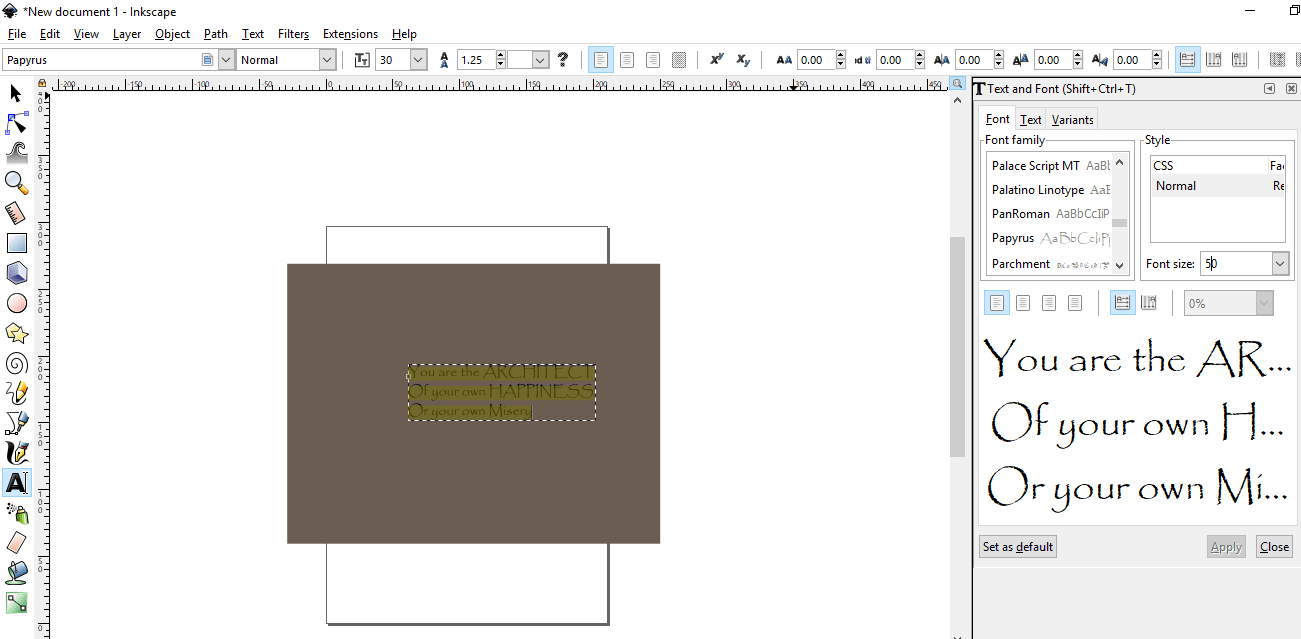
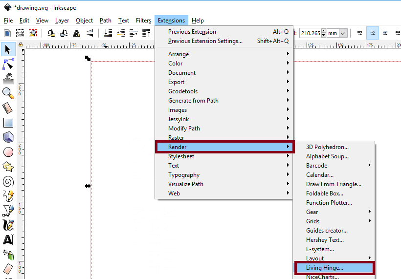
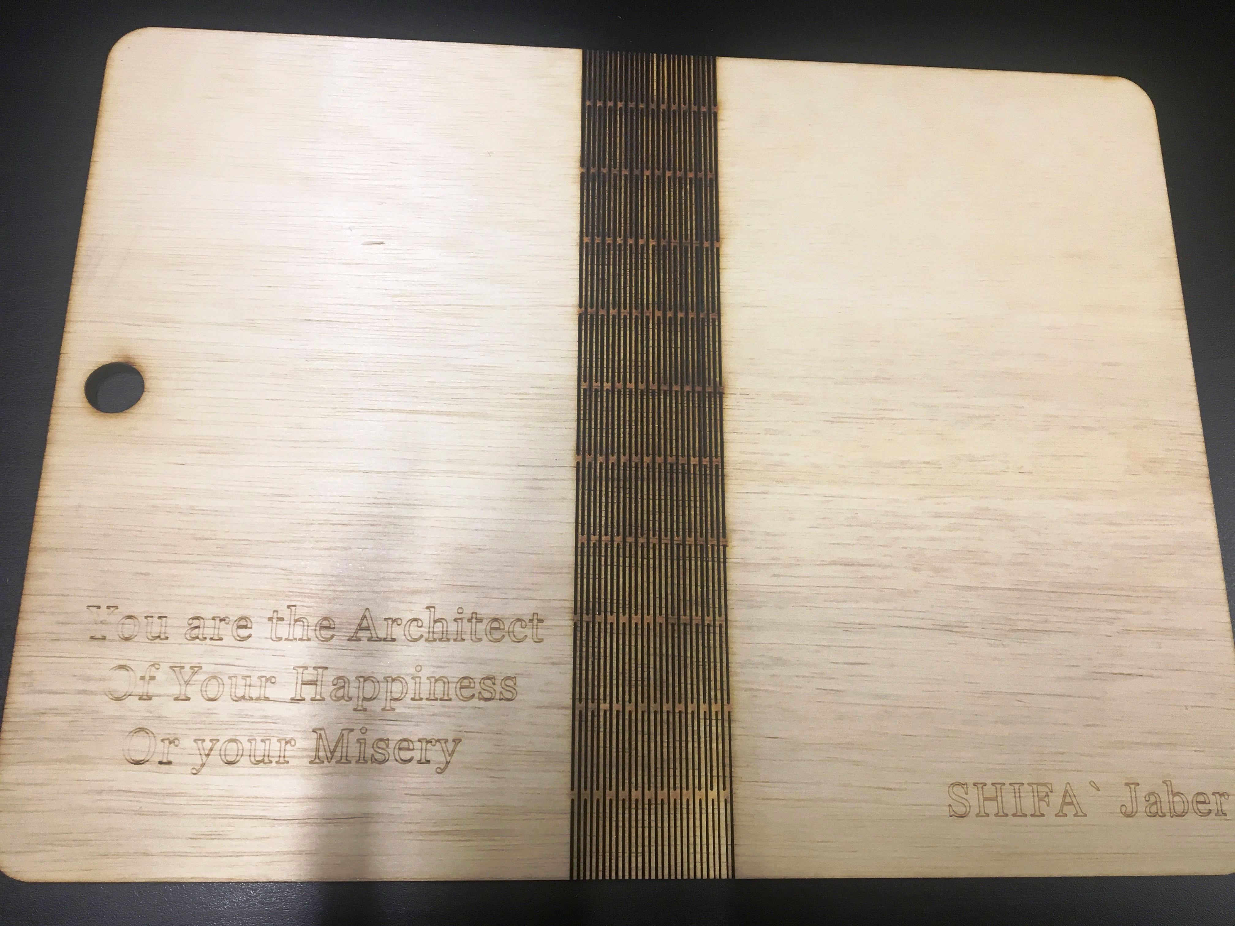
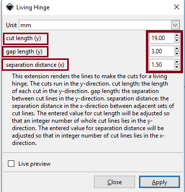
Using Living Hinge in my design to make the material flexible by cutting it, first I install the extension for the lining Hinge
When I chose Render from extension menu the living hinge will appear.
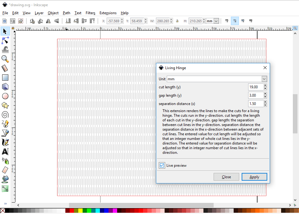
The extension dialog has a few parameters to set.
Change the cut length to 19.00 this is the length of each cut in the hinge.
The gap length is 3.00 which is the distance in y-direction between adjacent cuts.
The separation distance is the separation in x-direction.
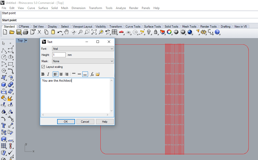
Using Rhino software to print from it.
The text of my cover didn’t appear, so I rewrote it using the text tool in Rhino, and edited the dimension because the scale was changed when I imported it.
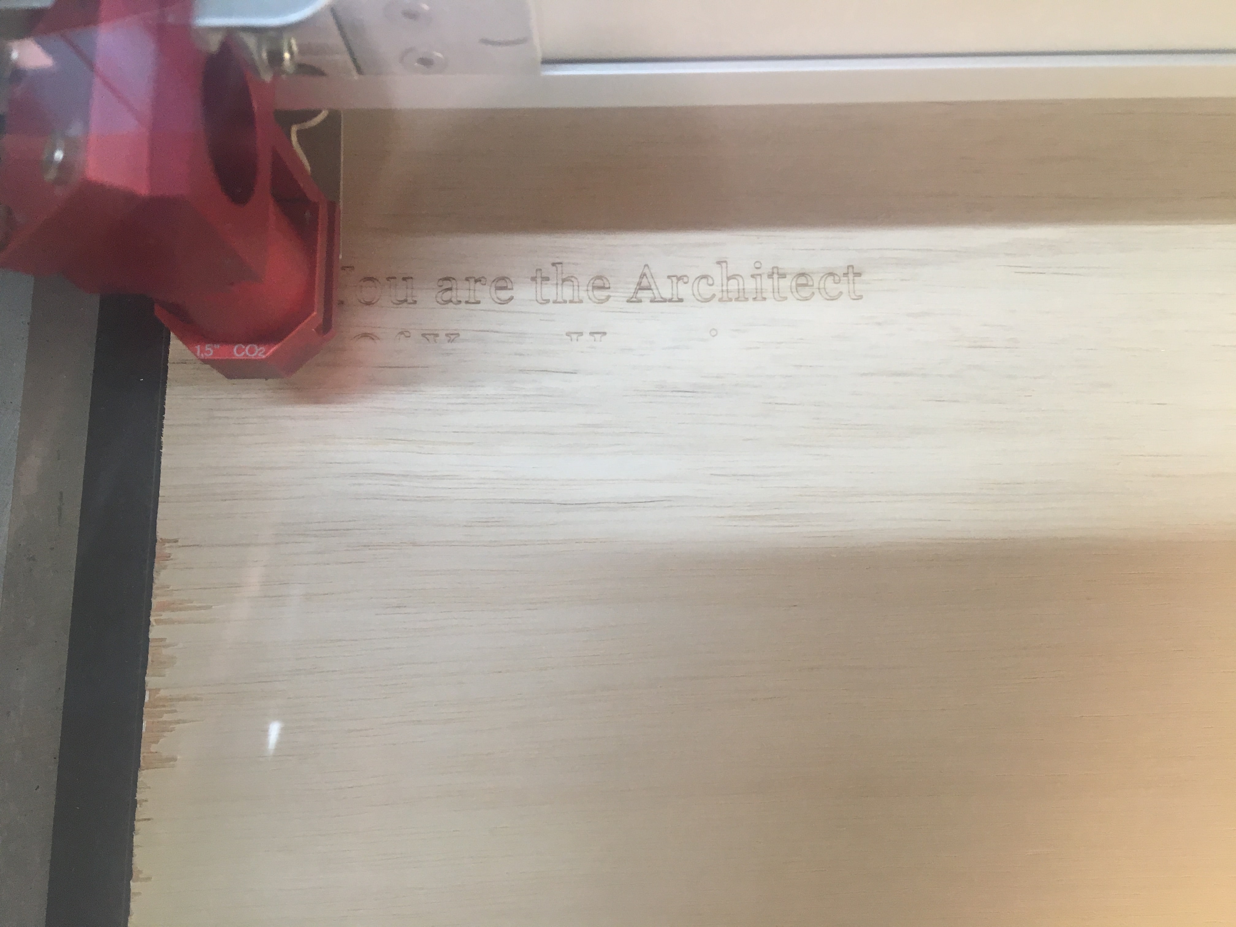
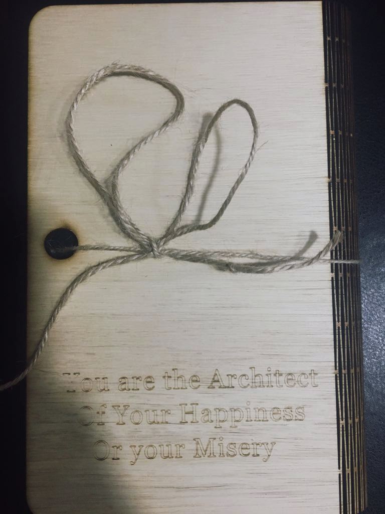
This is my cover after the laser cutting .
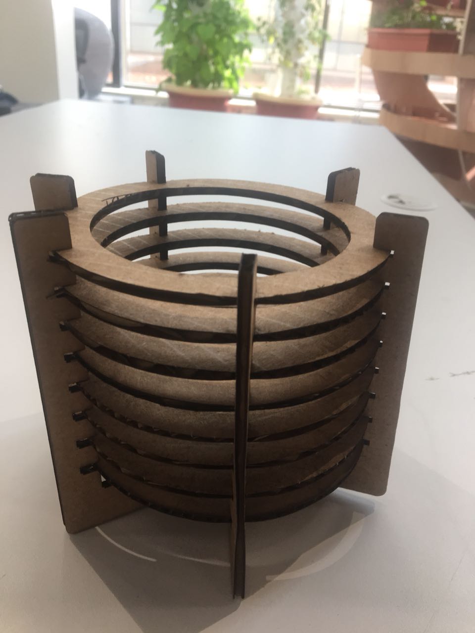
Pen holder
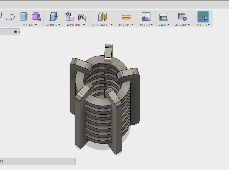
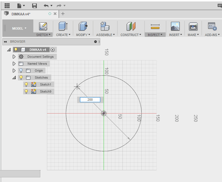
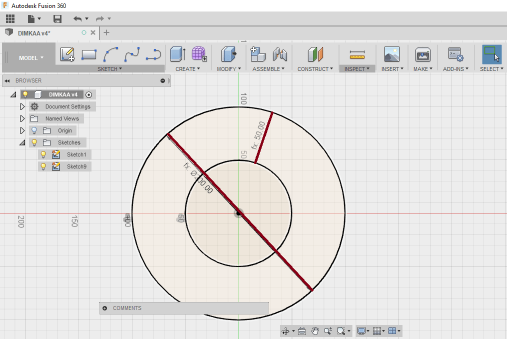
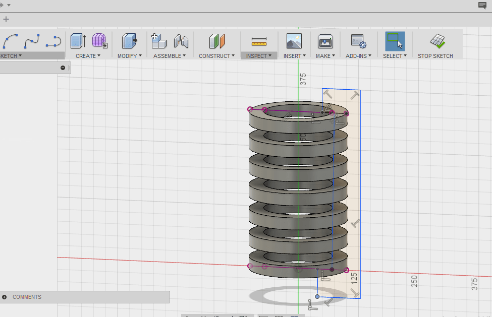
I also tried to make something parametric by Fusion 360
Start with drawing a circles with 200 mm diameter .
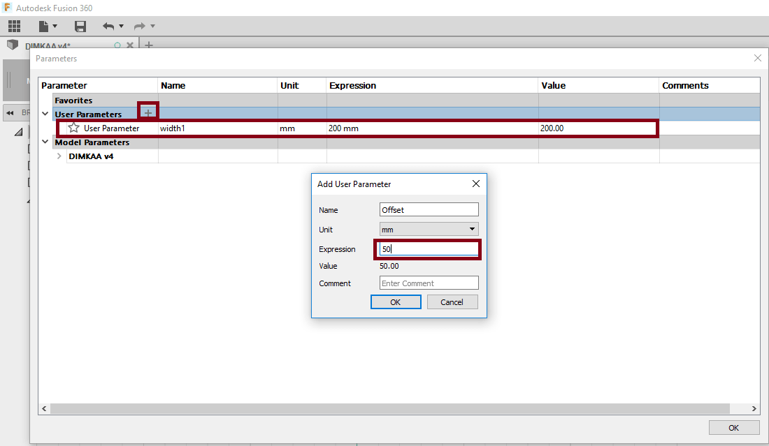
then make offset 50 mm.
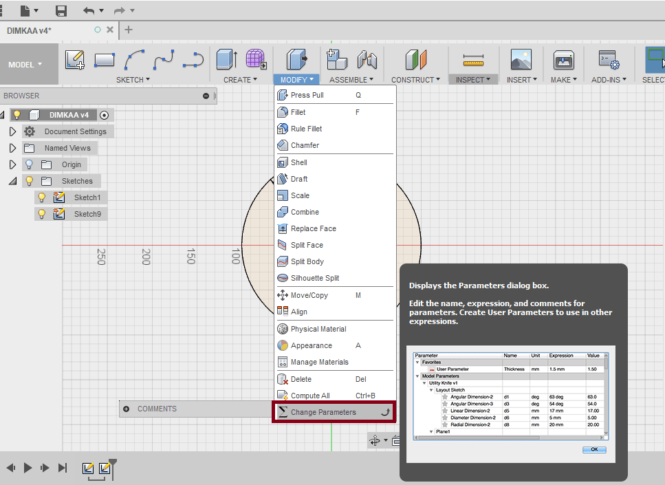
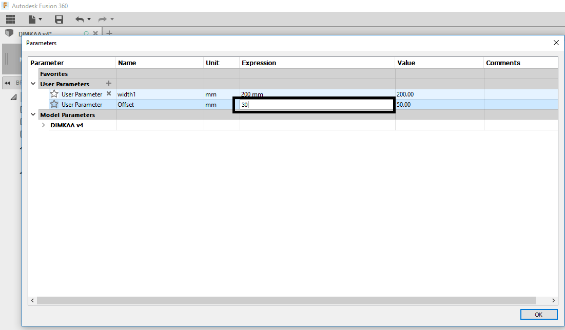
To make my design parametric from modify menu I chose Change parametric
Then put the value of the diminsion, If I change it my design will change because Fusion is parametric software
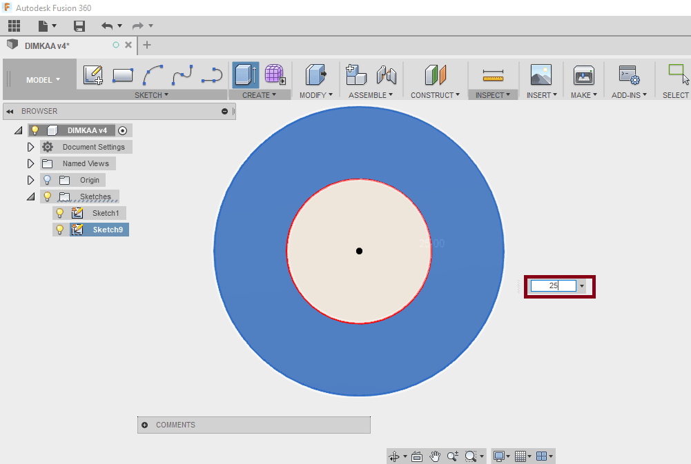
Extrude the circle 25 mm.
Change the offset value to 30 mm
Copy the circle 8 times
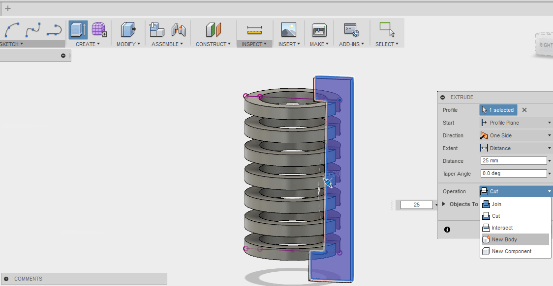
Draw a sktech from Sketch menu using Line tool this sketch will hold the 8 cicles.
Extrude the sketch 25 mm
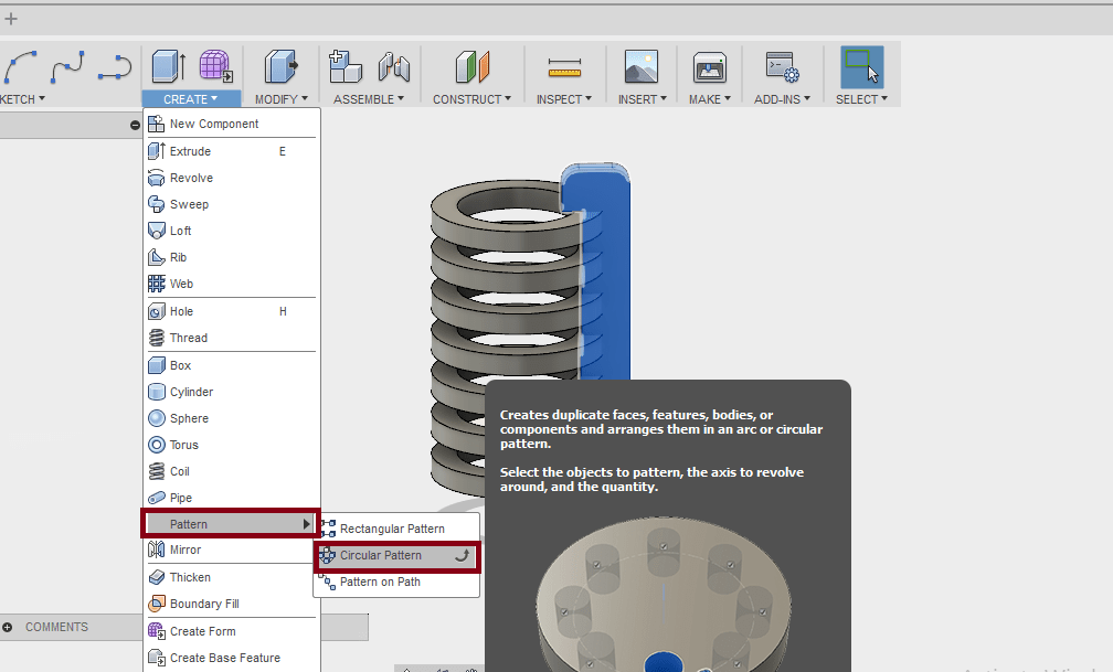
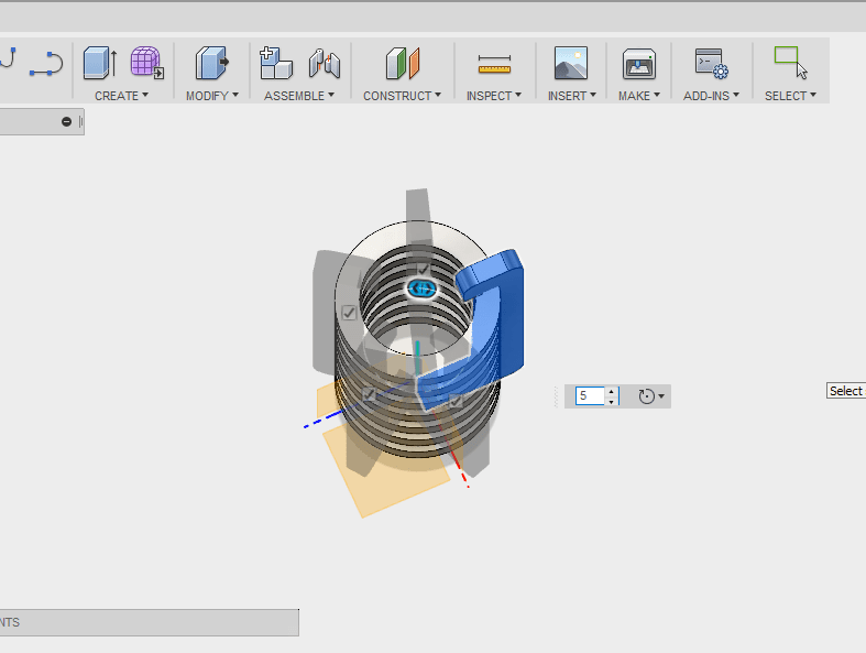
From create menu chose Circular pattern
The quantity of the pattern is 5
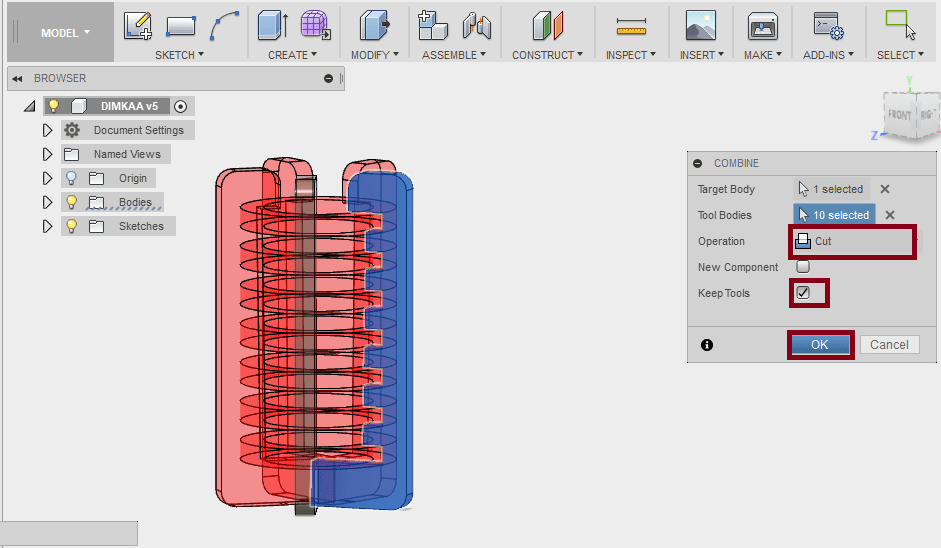
Then subtract the holders from the cicle, chose combine menu then chose cut tool
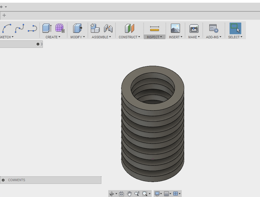
This is the final result.
I used the Cad software Corel draw Corel draw to cut my file, open the dxf files
Make the colors RGB red (255 ,0 ,0) then printed it.
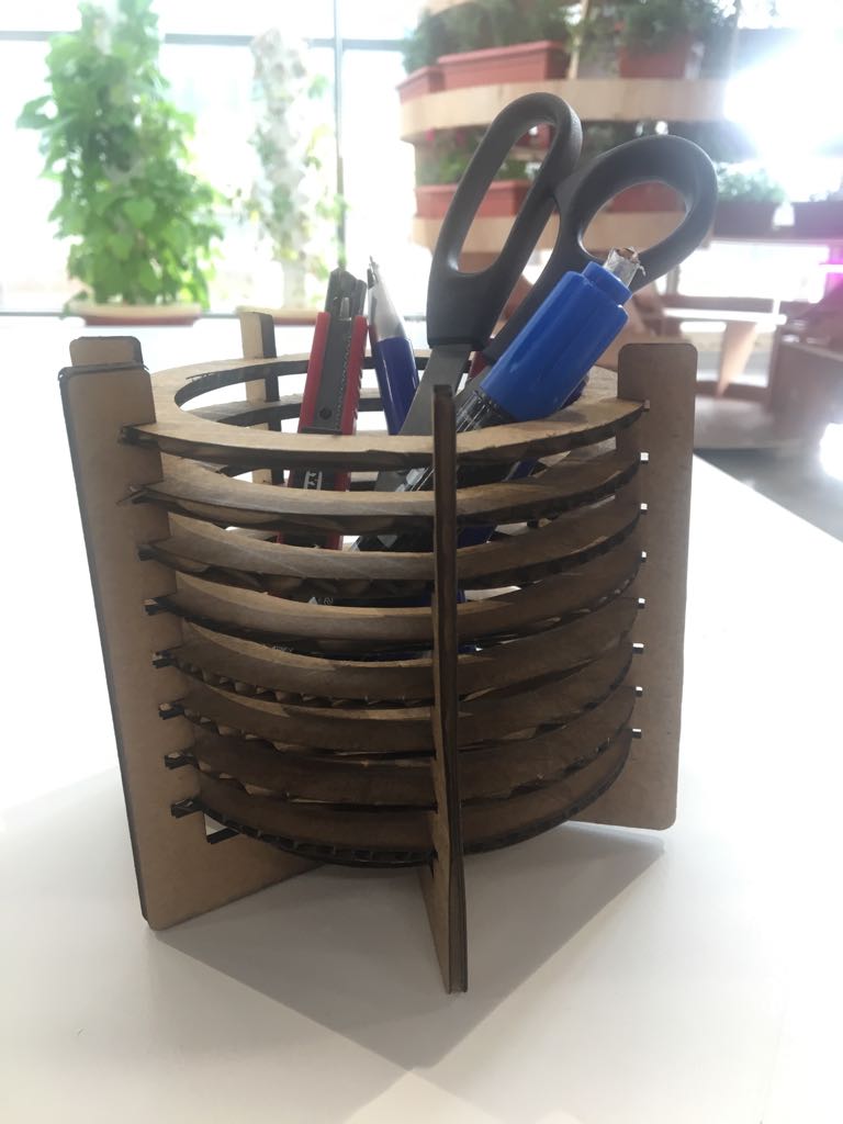
My Pen holder :
Download Files:
Vinyle Cutter file
Kerf .dwg file
Notebook Cover .svg
Pin holder
-min.PNG)