Contact Final Project Assignments My Lab About Me

Week 12

Output Devices

Assignment 12

Group Assignment:

Measuring Power Consumption of RGB LEDs

As one of our project is on RGB LEDs so we decide to find the power consumption of RGBs on different color pattern.
We write some codes which blink 1 RGB with specific color and measure current on that project.

Code to check Red LED

Checking current of RGB when 1 RED is on
  • The current is measured 47mA which is multiplied with 5 Volts is equal to 235mW.


  • Code to check Green LED

    Checking current of RGB when 1 Green is on
  • The current is measured 40mA which is multiplied with 5 Volts is equal to 200mW.


  • Code to check Blue LED

    Checking current of RGB when 1 Blue is on
  • The current is measured 48mA which is multiplied with 5 Volts is equal to 240mW.


  • Code to check White LED

    Checking current of RGB when 1 White is on
  • The current is measured 78mA which is multiplied with 5 Volts is equal to 390mW.


  • Code to check Black (no LED) LED

    Checking current of RGB strip when no RGB is glow

  • The current is measured 32.1mA which is multiplied with 5 Volts is equal to 160.5mW.

  • Different colors have different current consumptions. As per results we found that green color have low power consumption and white has maximum power consumption.


  • Individual Assignment:

    In this week I decided to make a circuit that will be used to operate a servo motor. Since it will be helpful for me ahead. Inorder to complete this assignment I followed the following steps:

    1.Making Circuit

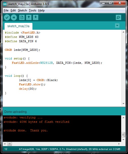
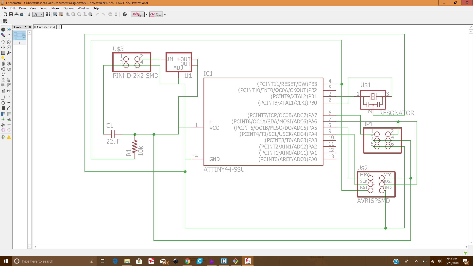
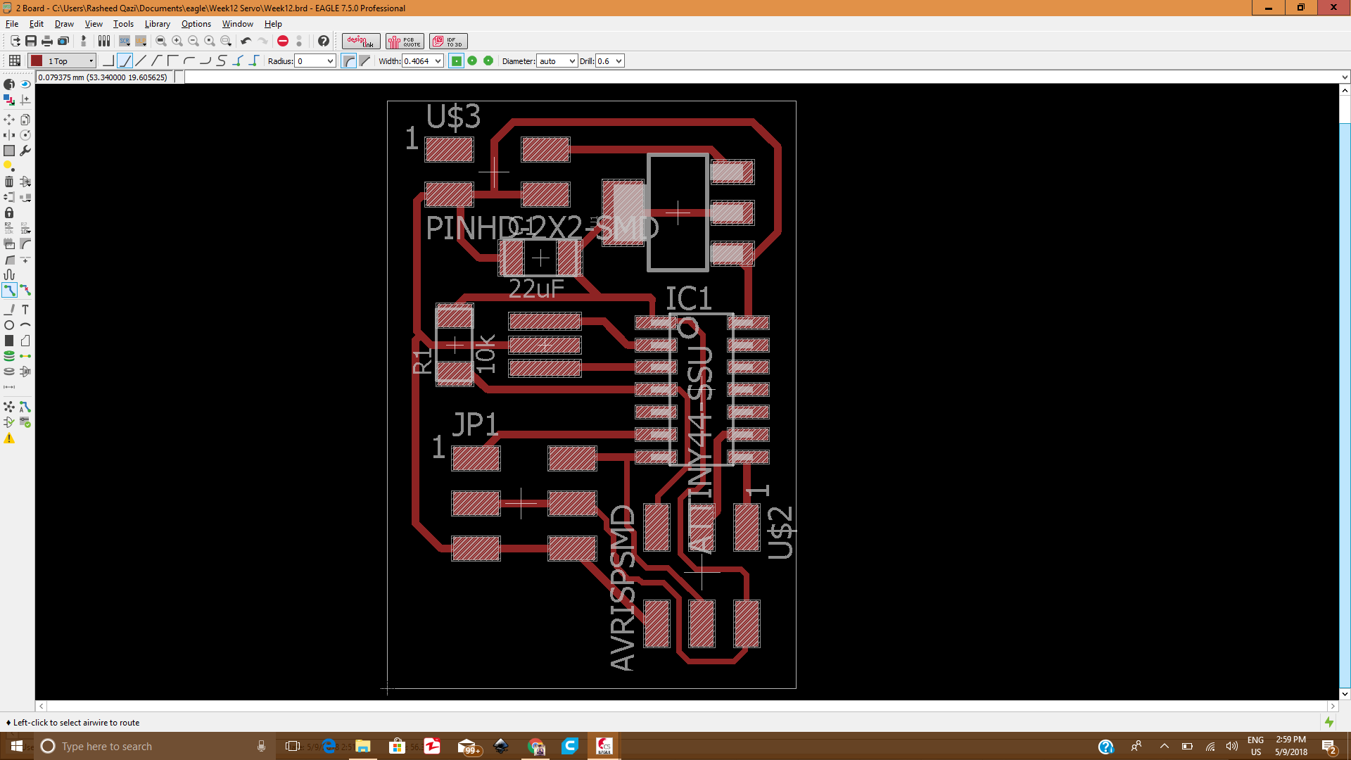
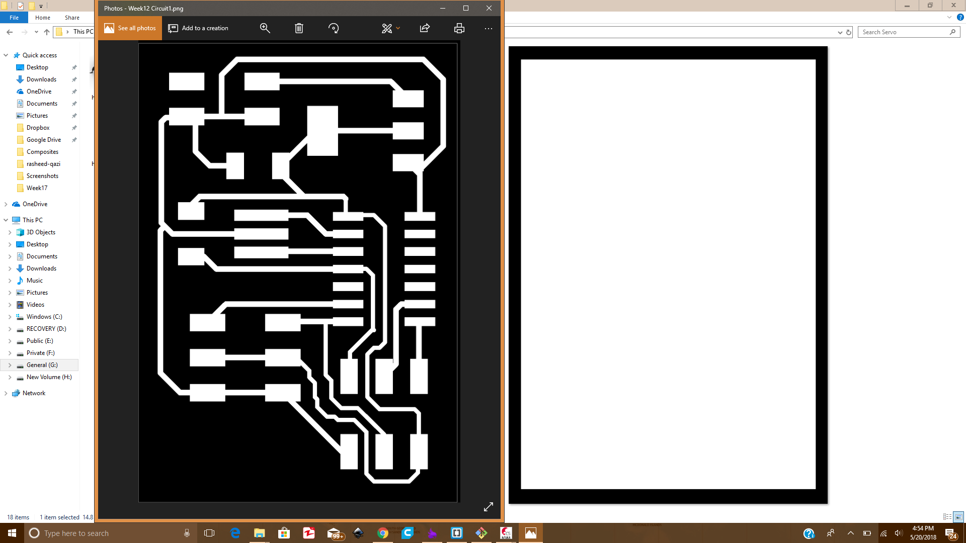
    I designed the circuit in Eagle software. The other steps were similiar to electronics production. Following pictures shows the circuit at different phases:

  • After completing the circuit schematic connections it looked like this:
  • Schematic of Circuit

  • Then working on the board file and connecting the components using copper traces, the circuit was like this:
  • Board file of the circuit in Eagle

  • After that we had the Traces and Outline of the circuit
  • Traces and outline

  • Similiarly I had generated the RML files for both Traces and Outline
  • Toolpaths of outline and traces

    2. Milling and Soldering

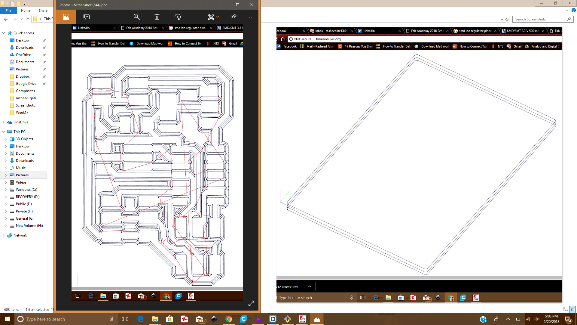
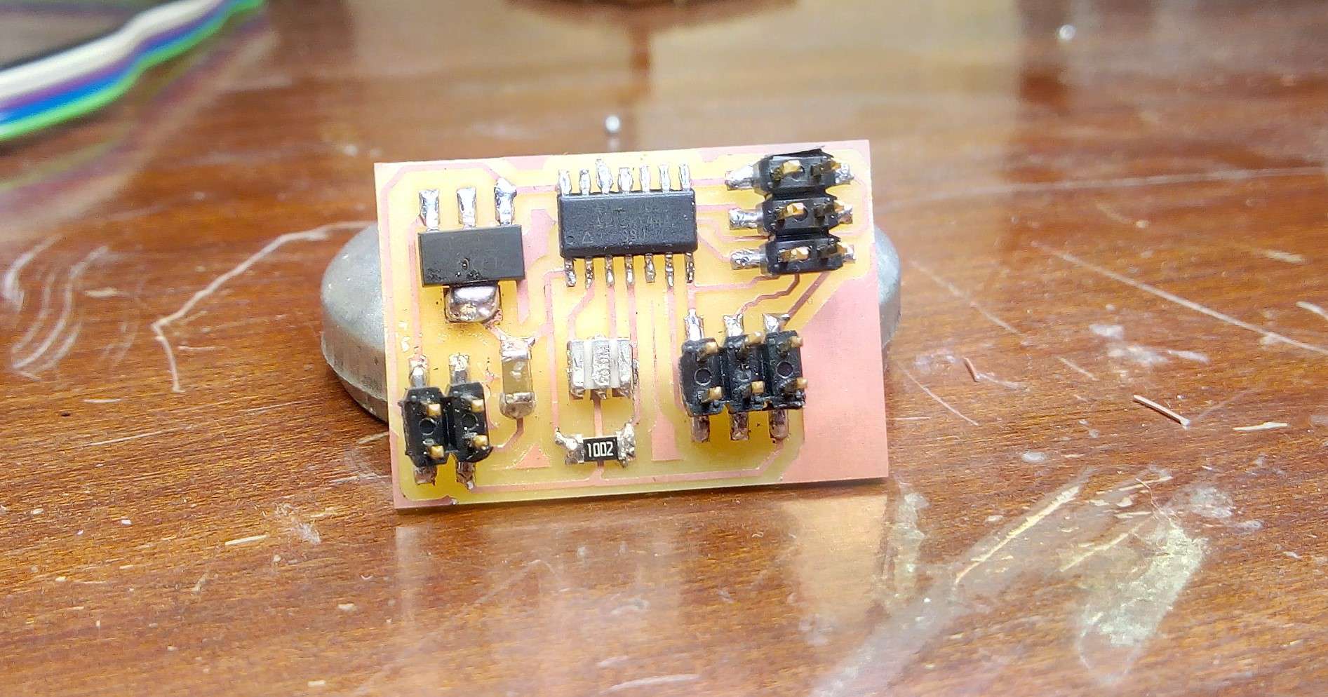
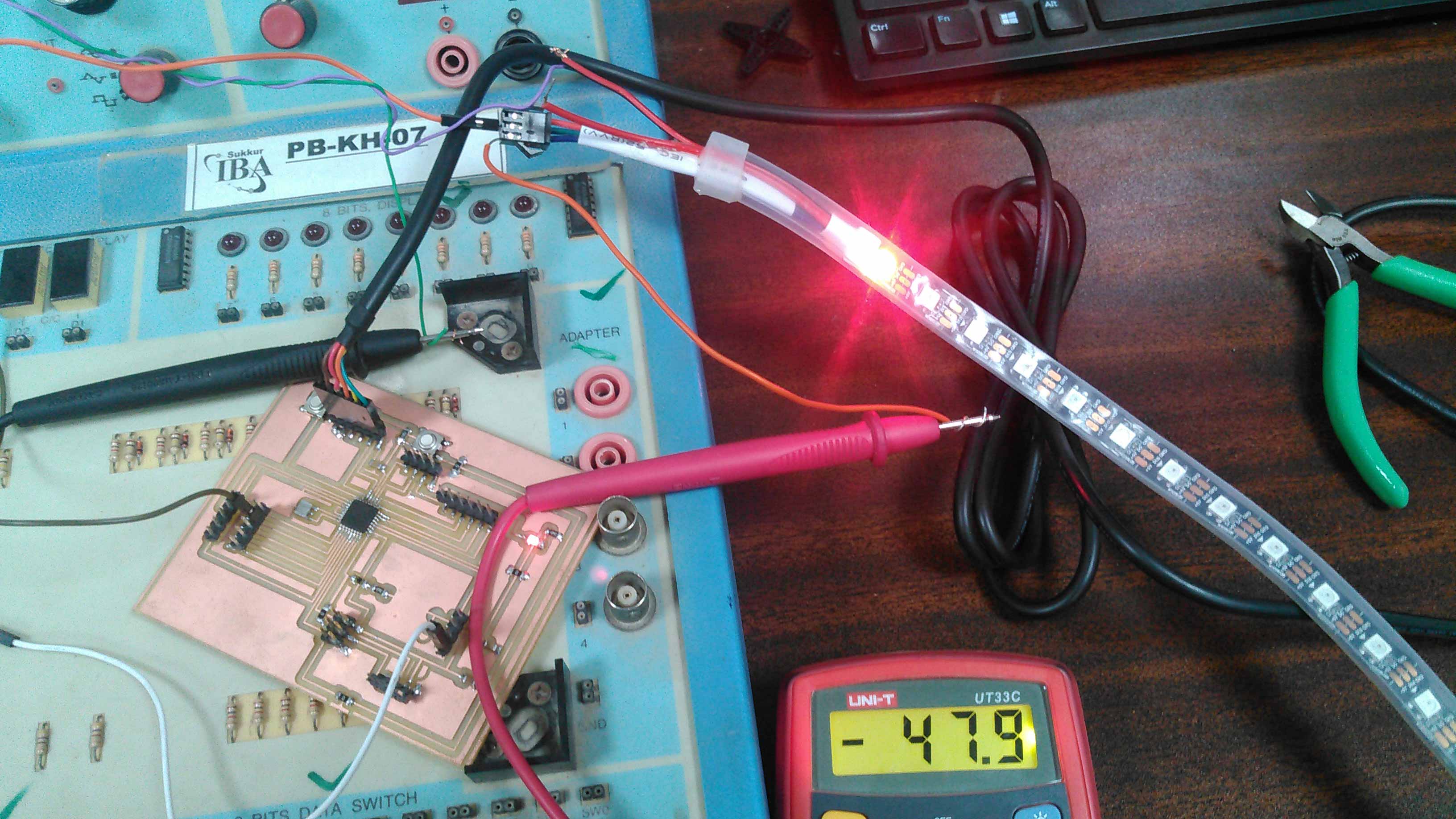
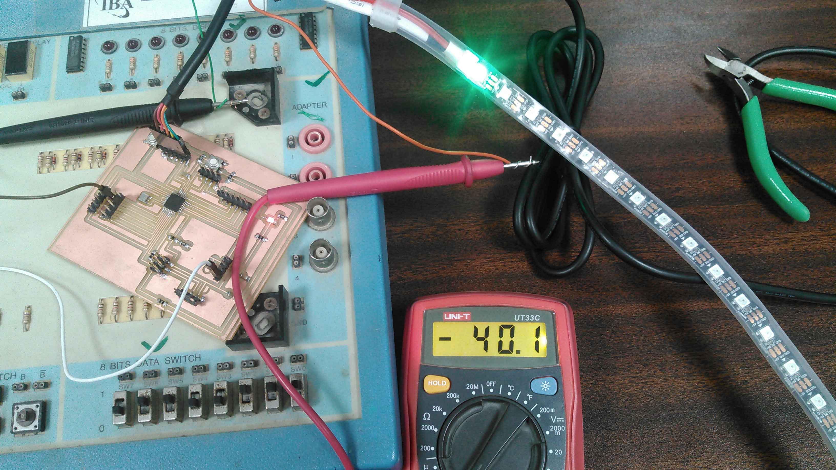
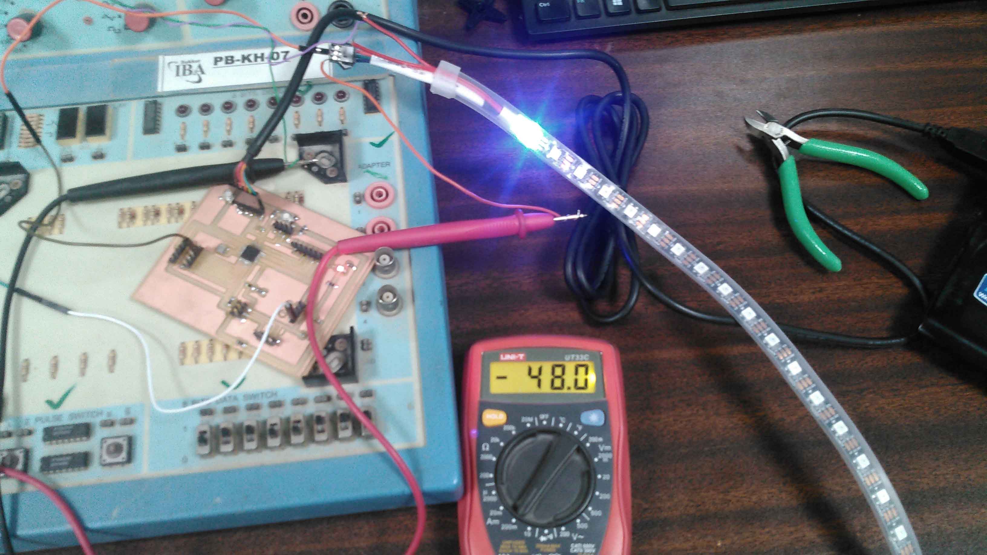
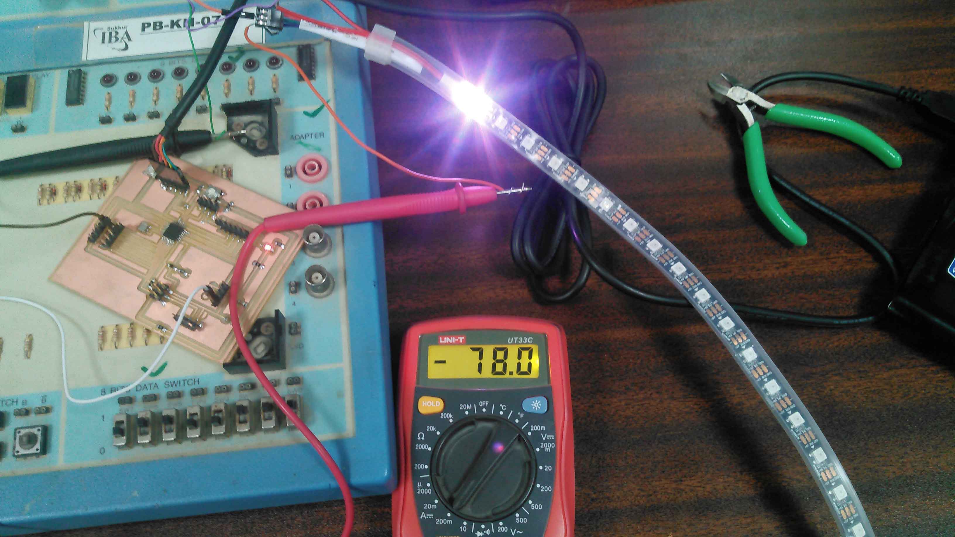
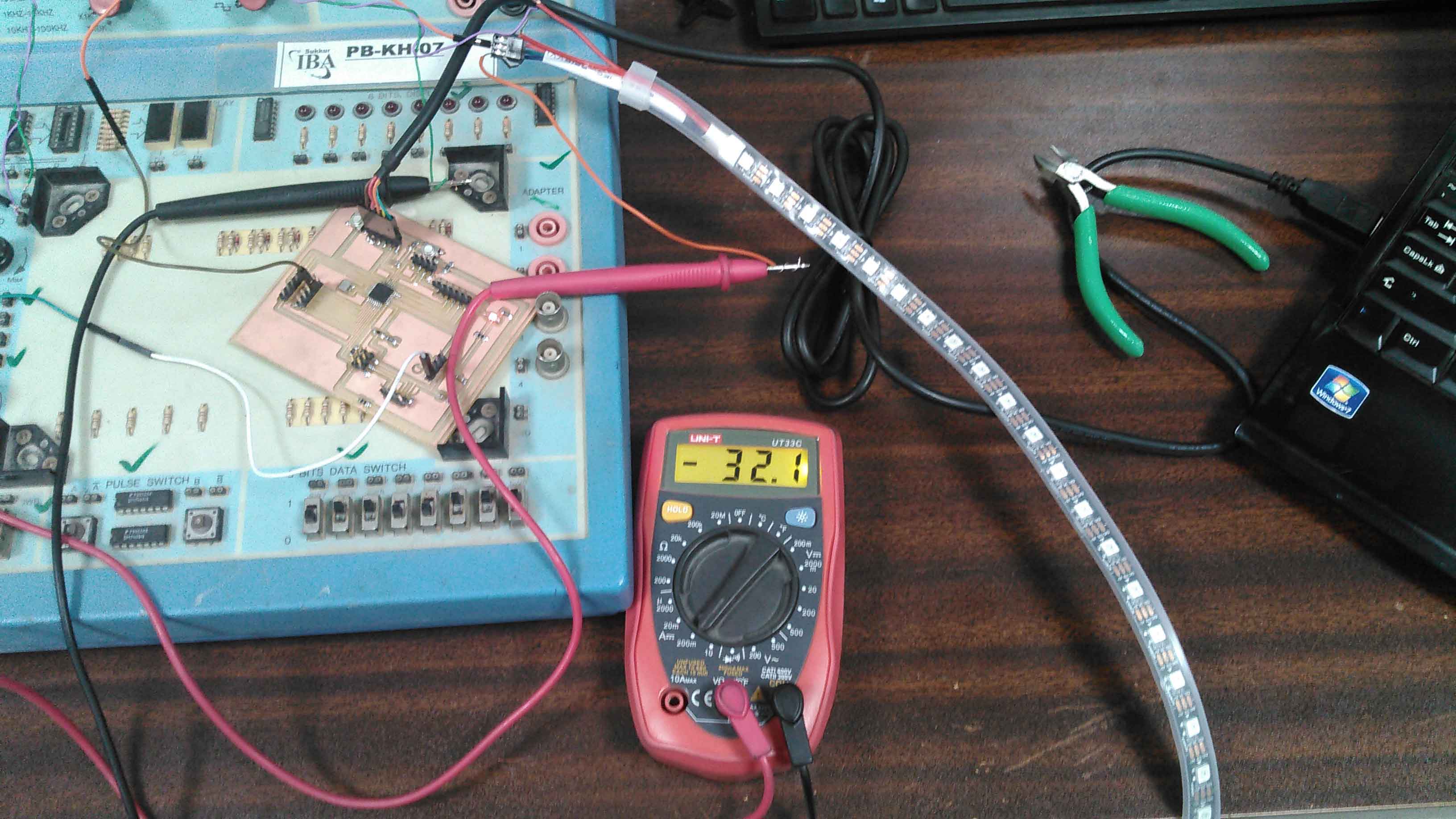
    Then milled the circuit, and solder the components over it.

    Circuit after milling and soldering


    3. Programming and operating the board

    I started programming the board using My Fab ISP. And uploaded the sample code from website to check wehther the circuit is working properly or not. A snap of the code is attached below:
    C code

    Once the code was successfully uploaded, then I took the board and a servo motor and made the connections of them with the Variable power supply to observe the output results. A picture of that setup can be seen attached below:
    Setup to check the results of circuit

    Finally I turned on the power supply and observed the output of the circuit. That output now can be seen in the video given below:
    Video showing the working

    That's all for week12..
  • All the Files of Week 12 can be downloaded from Here.


  • Creative Commons License
    This work is licensed under a Creative Commons Attribution-NonCommercial 4.0 International License.