Assignment 07
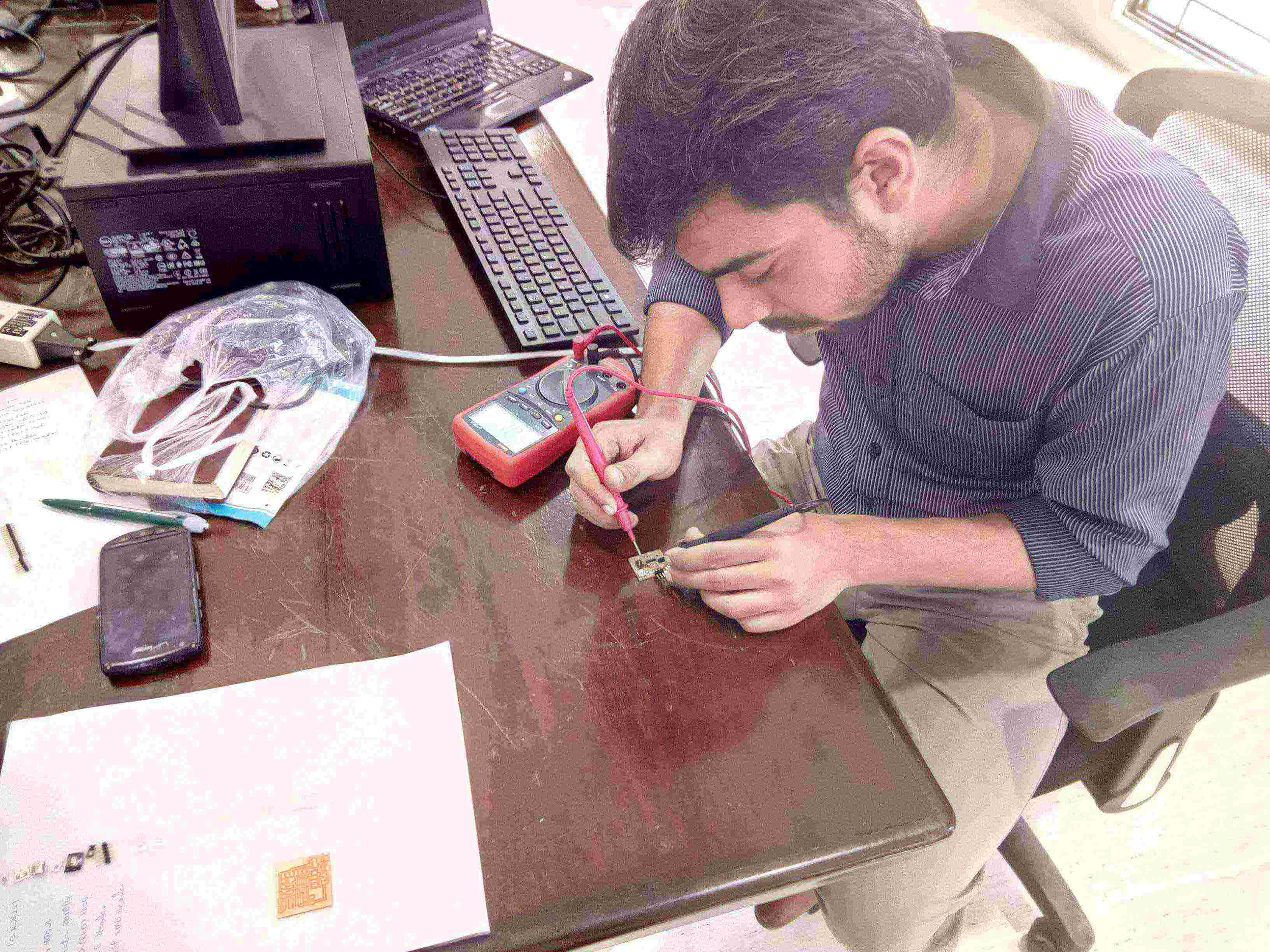
- Group project: Use the test equipment in your lab to observe the operation of a microcontroller circuit board
- Individual project: Redraw the echo hello-world board
- Add (at least) a button and LED (with current-limiting resistor)
- Check the design rules, make it, and test it
Group Assignment:
1. Multimeter
"A multimeter is for electronic engineer as stethoscope is for doctor". It is most convenient and helpful equipment when we test or measure electronic components. We decided to check component in echo-hello world circuit using multimeter to confirm the values of components and to check either they are in working condition or not.
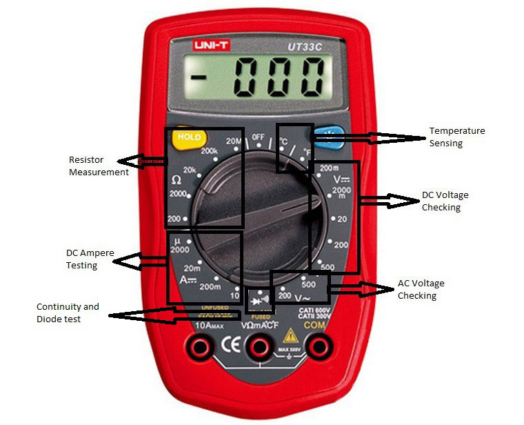 Multimeter function description
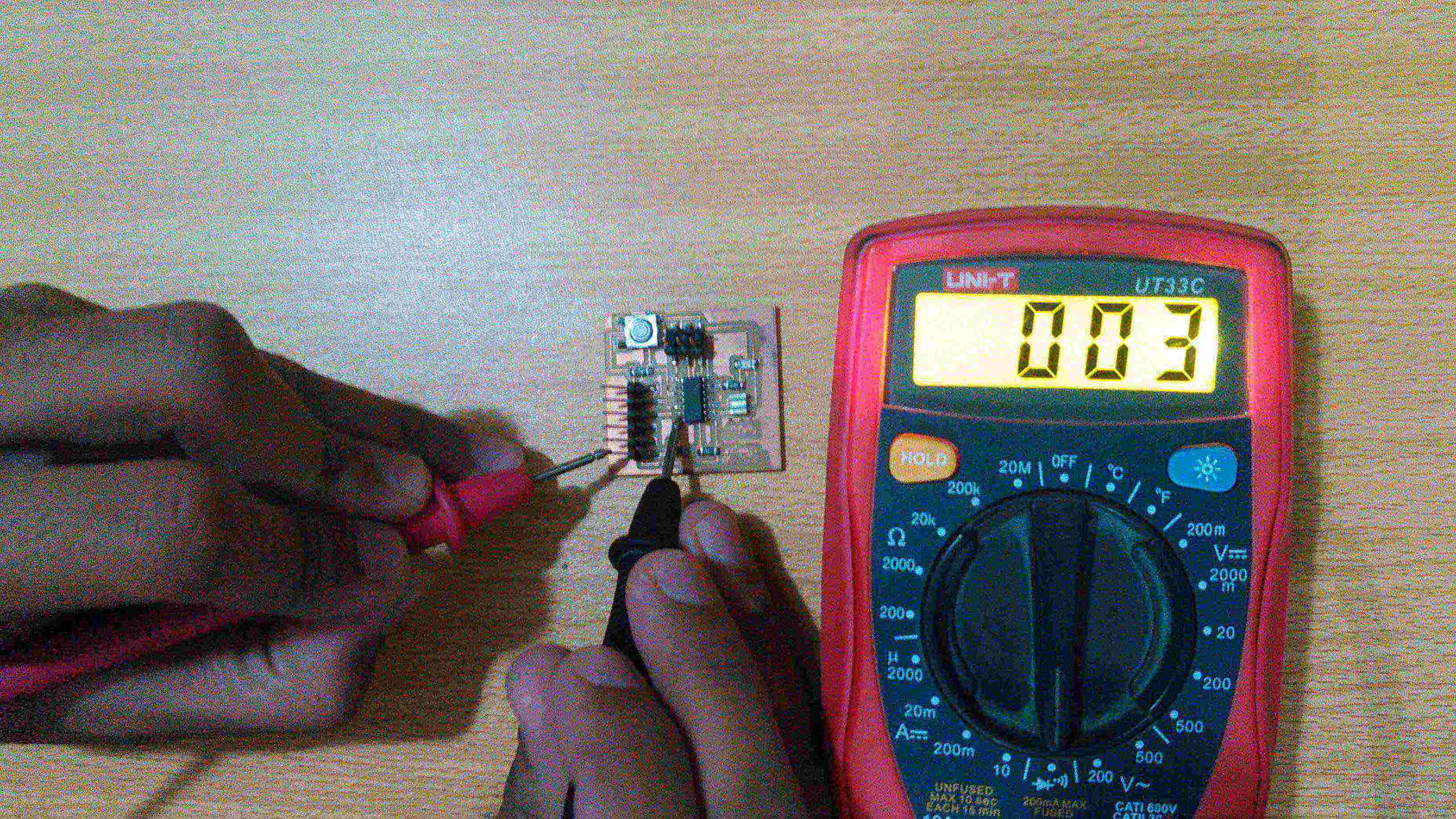
2. Continuity and Diode Testing
To test the continuity and diode first turn the dial of multimeter on continuety testing function which is mentioned in above picture. Continuity test is done by checking circuit tracks with probes, if beep occurs it means that tracks are connected if there is no sound of beep or shown "1" on screen it means that tracks are not connected.
 Connection testing from attiny 45 ground to FTDI ground
 Button testing multimeter beeps when button pressed
To check the LED we placed the black probe on cathode side (which is marked green in our LED) and red probe on anode side, if LED glows it means that it is in working condition.
 LED testing
3. Measuring Resistance
In a echo-hello world circuit we have 3 resistors, 2 are 10k ohm and 1 is 499 ohm resistor with 1 % tolerance. To check their values we moved the dial to "20k" in resistor measuring portion and measured them.
 Measuring resistance
4. Voltage Supplies
A circuit is powered via FTDI cable which has 6 pins in which black one is GND and red is VCC. We checked the potential difference by placing black probe on GND pin and red probe on VCC pin to check the voltage. Then we check voltage in circuit by powered it with FTDI Cable.
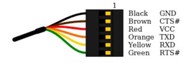 FTDI Cable pinouts
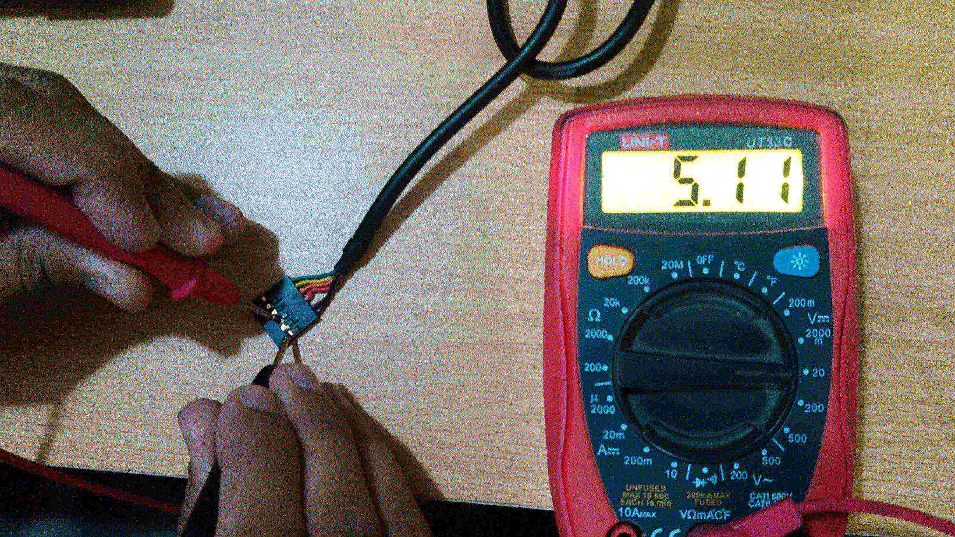 5V from FTDI Cable displays in Multimeter
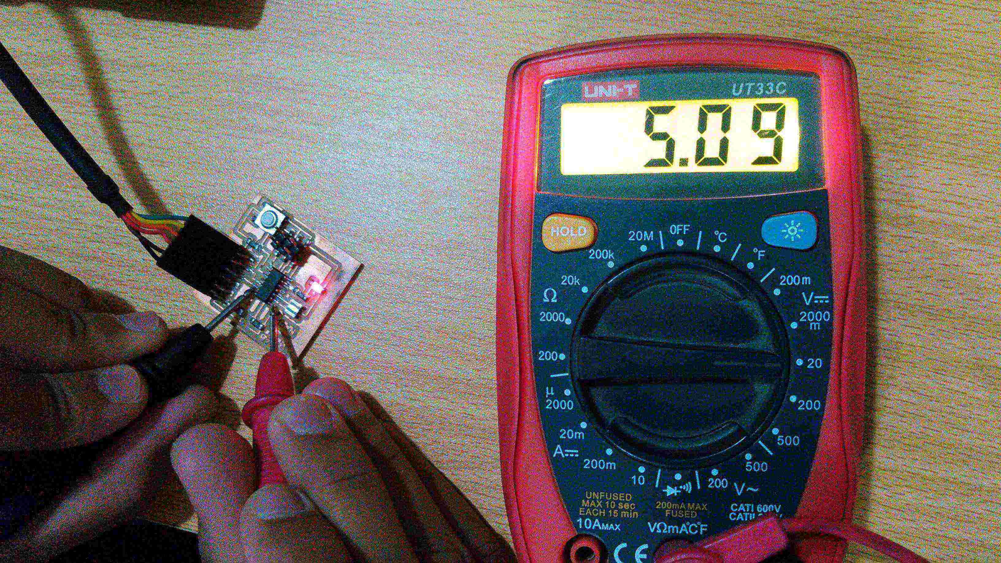 5V Voltage in a circuit
Individual Assignment:
Redrawing the echo hello world circuit
For circuit designing we were introduced to many different softwares during our lecture on Wednesday. Among all the other softwares i chose to work on Eagle for circuit making. Before start working on the tasks, I downloaded the necessary material from class schedule. First thing was the original Hello world circuit which is shown below:
 Basic hello world circuit board
Once you get to know what circuit you have to make, now we should start making it. For making the schematic of this circuit we need its electronic components, for that we need to download and copy the respective library in the Eagle directory. The fab library for eagle can be downloaded from
Here. Further steps for loading the library in eagle and using it are shown below:
 Steps to load the fab library in eagle
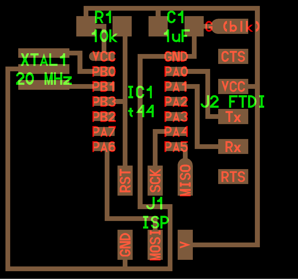
After loading the fab library, i started making the circuit with an addition of button and LED in it. Once i was done with it, the schematic of my circuit looked like this:
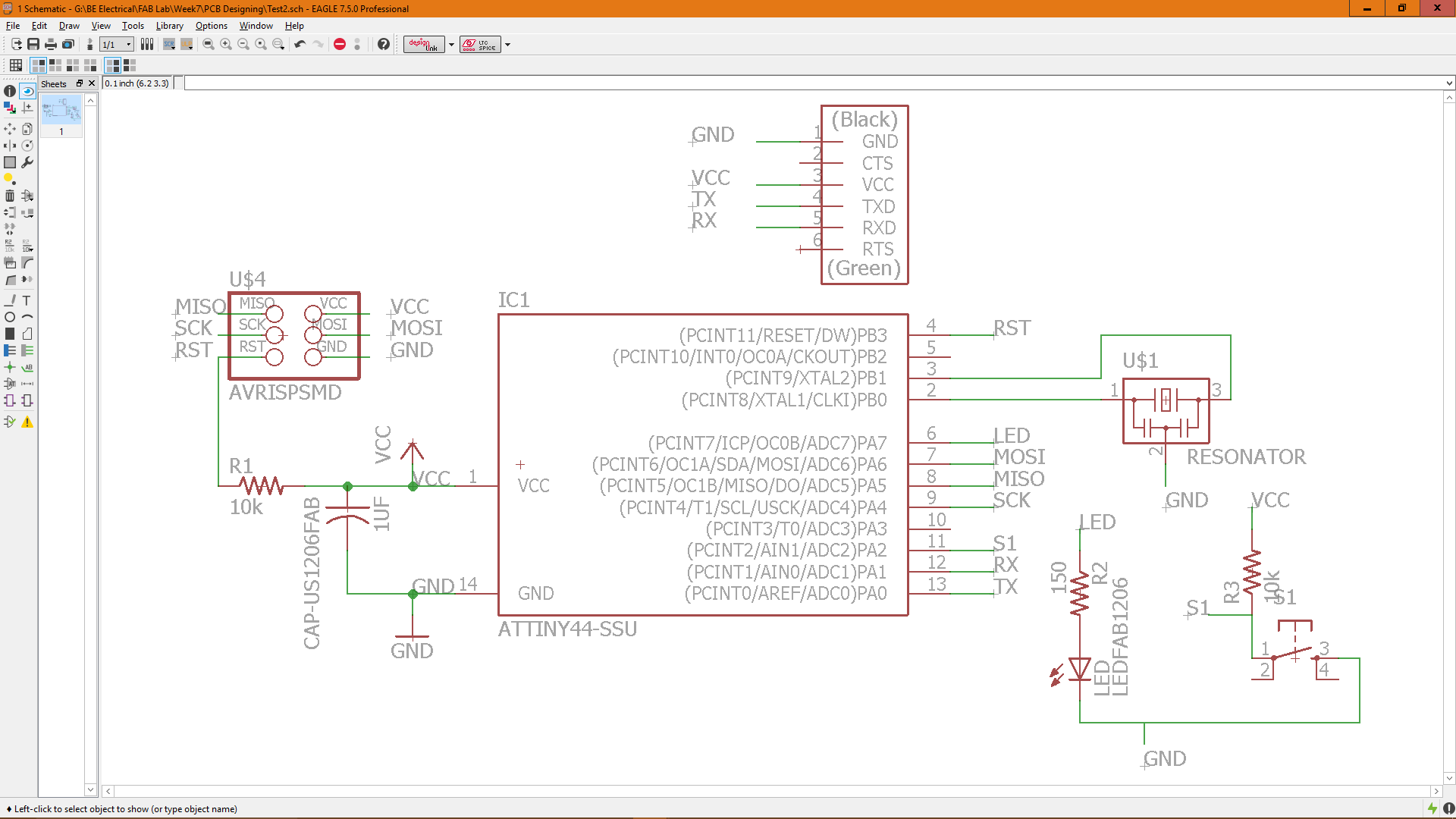 Schematic diagram of my circuit
As the Schematic design is complete, now is the time to go to .brd file and routing the traces of PCB, for that i followed the following steps:
 Going to Board file from Schematic file
Once I connected the copper traces of PCB board between the components, I ran a DRC Check over the design in order to observe the design rules. Before applying the DRC check, I went to other tabs to check what are the value for clearance, distance and size they are shown below:
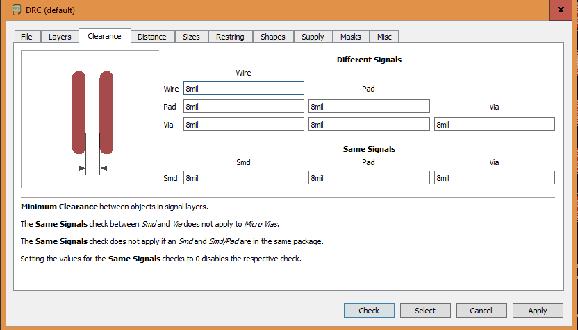 Values for clearance
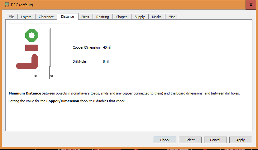 Values for distance
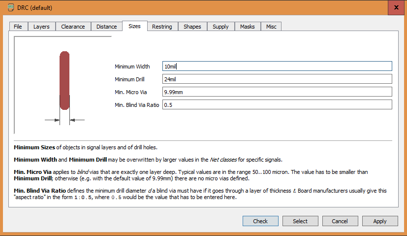 Values for sizes
and then I clicked on the check button to run the DRC, and there were no errors.
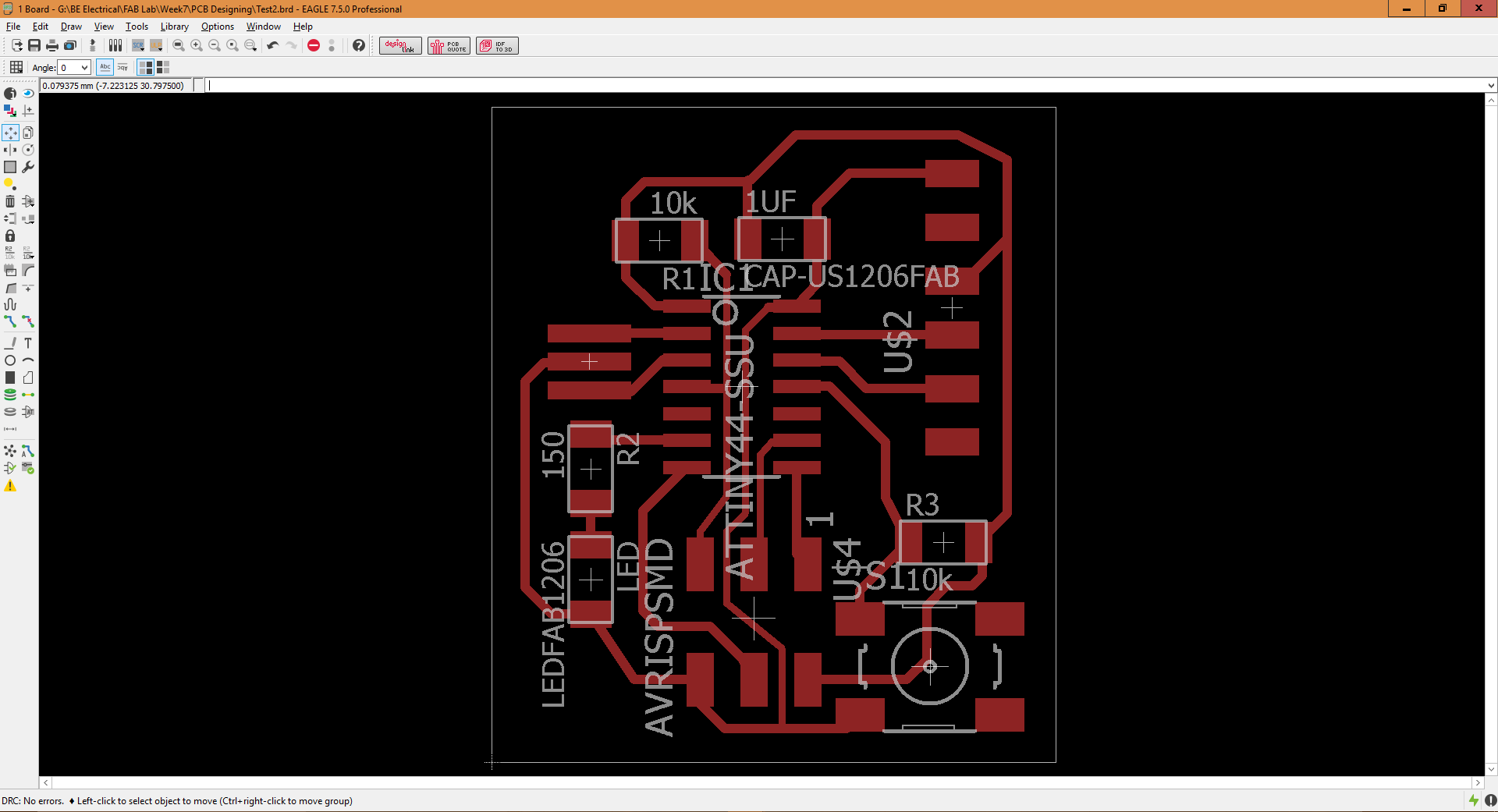 No errors in DRC
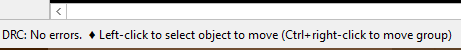 Showing status of no Errors
This is the part where your circuit designing skills are tested, now you have to place the components in such manner as you want them to be mounted on your PCB. After arranging the components:
Select the "Route" option and start connecting them with each other
Use "Ripup" tool (right beside the "Route" tool) to delete any unwanted connection you made.
Once the connections are completed, check for errors. If there are any overlaps, try to move the traces away from each other or else reduce the width of those traces to avoid overlapping
Go to layer settings and disable all layers except "Top" and "Dimension" layer
Now go to "File", "Export", "Image"
Select the quality in DPI as 1200 or above
Select the "Monochrome" option
Browse for location and save the image as .png file
 Steps to export the traces as .png file
Then I photoshopped the .png file inorder to put my initials on the circuit:
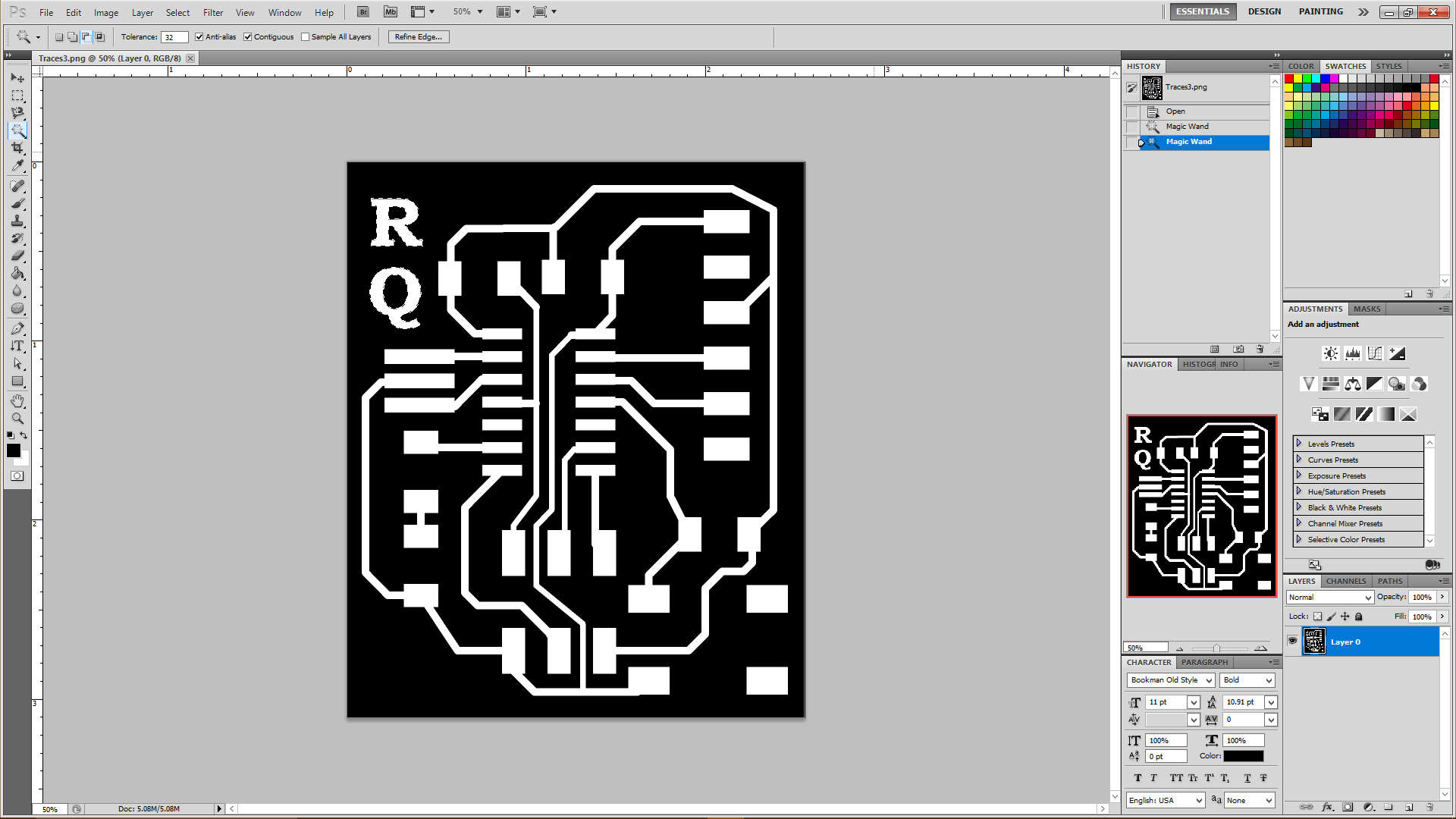 Writing Initials on Traces
Now comes the time to generate .rml files for milling the circuit. For that we will follow the steps performed while making ISP.
Basic steps for making an .rml file:
- Go to mods.cba.mit.edu
- Upload your .png file
- Select the width of tool, i.e. 1/64 for Traces and 1/32 for Outline
- Save the .rml file generated
Shown below are the rml files showing the tool path for
Traces and
Outline.
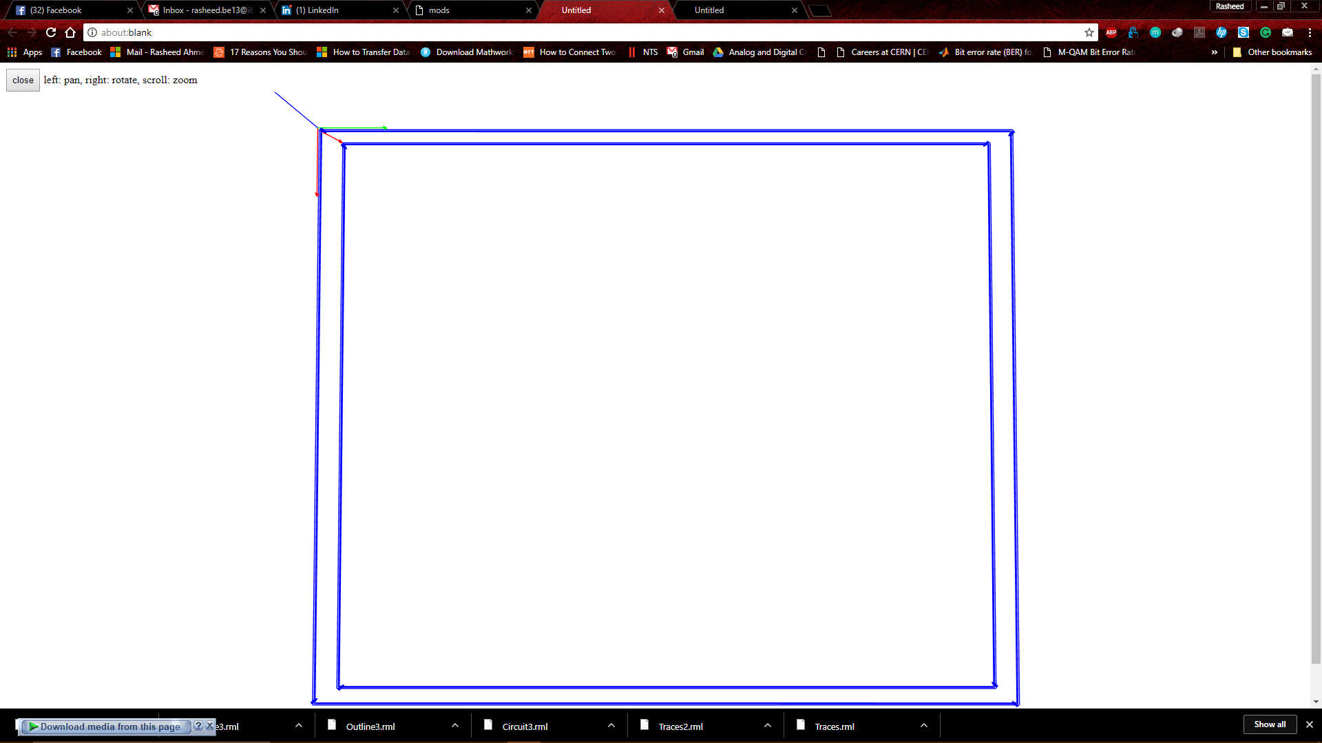 Tool path for Outline of Circuit
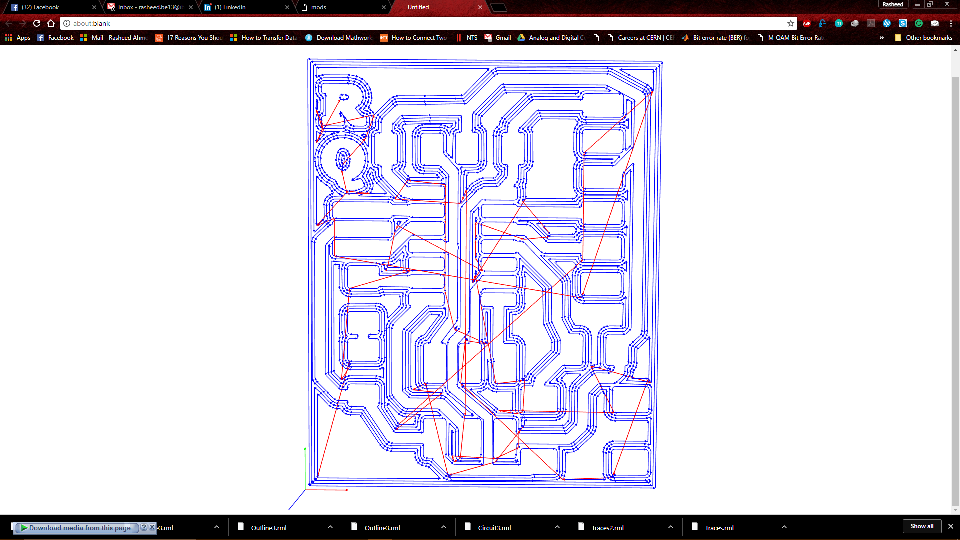 Tool path for Traces of Circuit
Milling
Tool path for Traces of Circuit
Milling
We are now ready to start milling our circuit, connect your PC with
SRM-20 machine and use the .rml files generated in previous step. Apart from that make sure to take care of following things everytime you operate "SRM-20" machine:
- Select the appropriate tool for appropriate job, don't get confuse with them
- Always set the XY origin first, and then carefully adjust the Z axis values
- Make sure to have a record of Machine Coordinate system in case of power failure, so that you may resume from the previous point
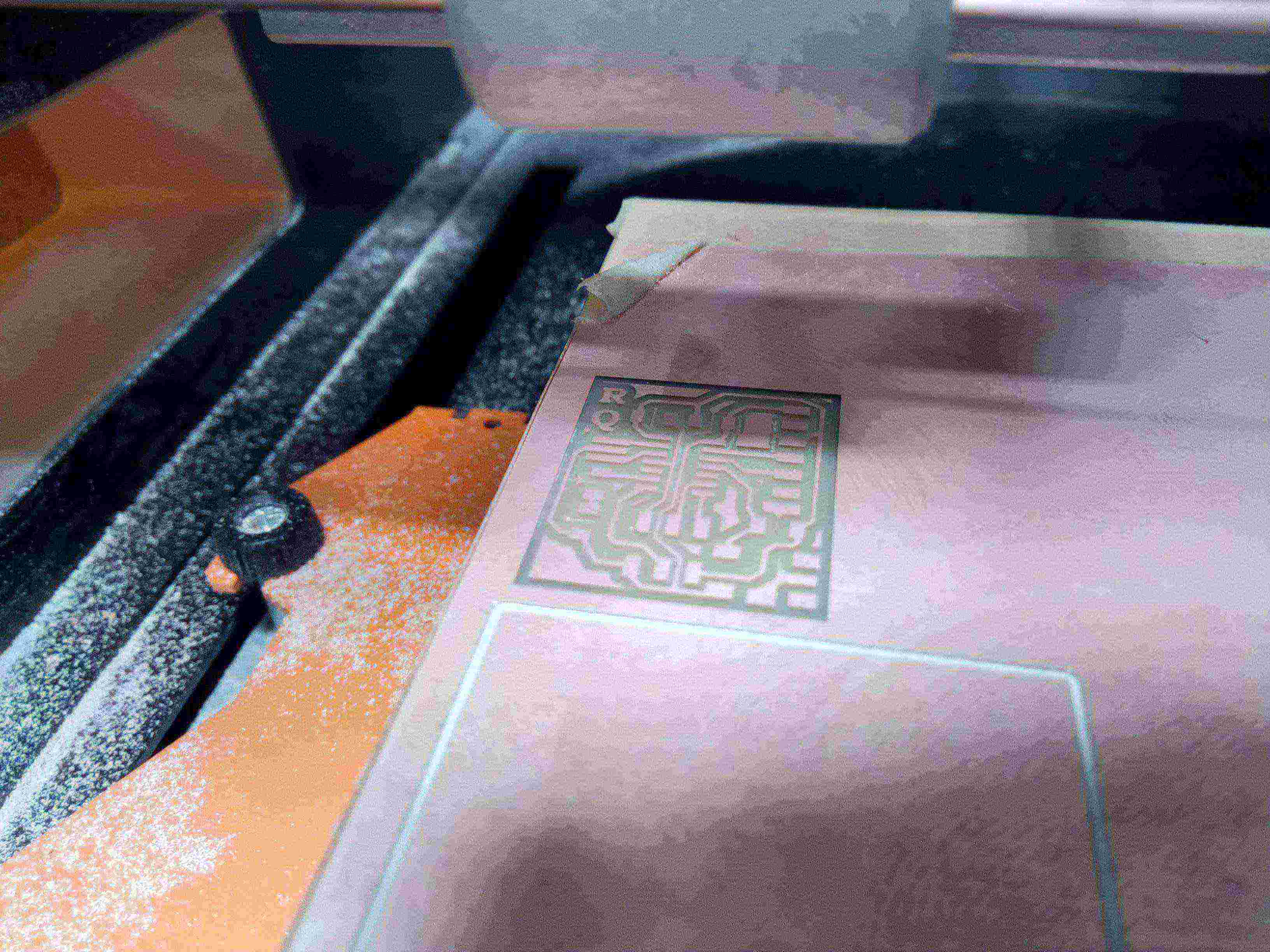 Circuit during milling
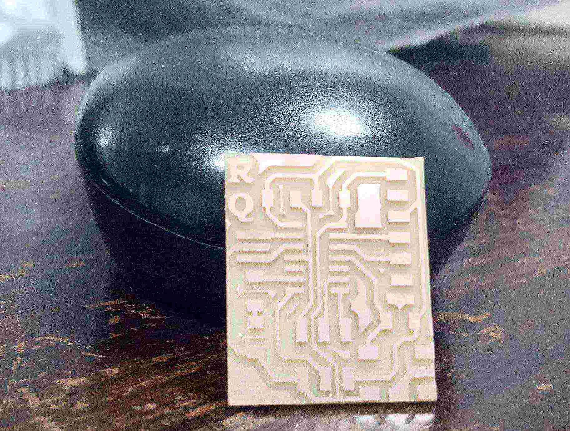 Circuit after milling
Soldering
Circuit after milling
Soldering
This is one of the most interesting part for me as i got the chance to improve my soldering skills on SMD components as well. Before starting the soldering of components over the PCB, but first i need to collect the components and below attached is the list of components along with the components attached to the right side of it:
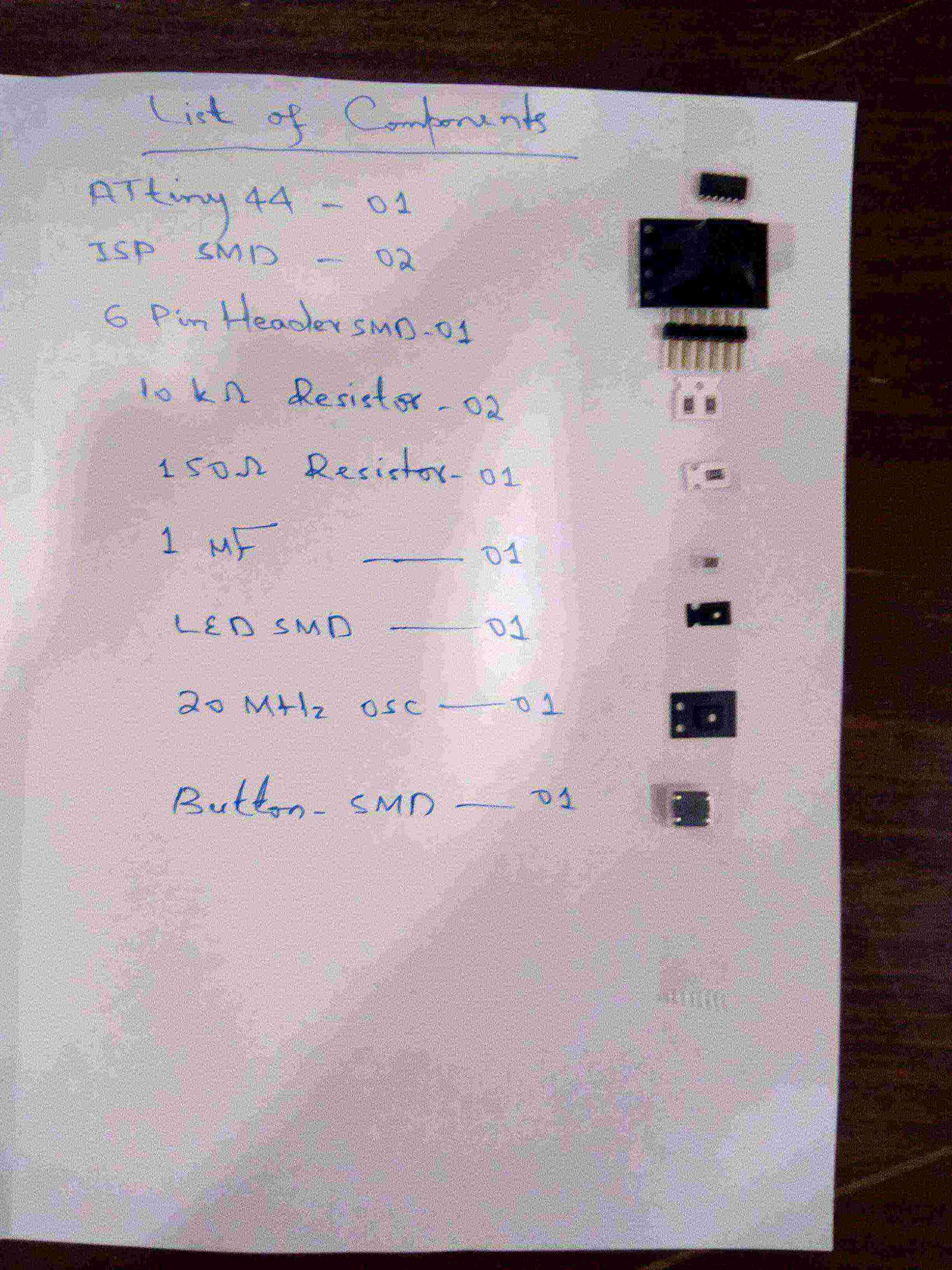 List of Components along with components
After soldering the components, it was the time to check whether the connections are proper or not. during that checking i came to know that one of the connection of ISP header was not complete because i made a mistake during the soldering and the "MOSI" pin of ISP header was not connected with the copper trace. So i needed to solder that pin again and the problem was gone and my circuit was all ready to go :D
 While troubleshooting my circuit
This is the final result of redrawn hello world circuit:
While troubleshooting my circuit
This is the final result of redrawn hello world circuit:
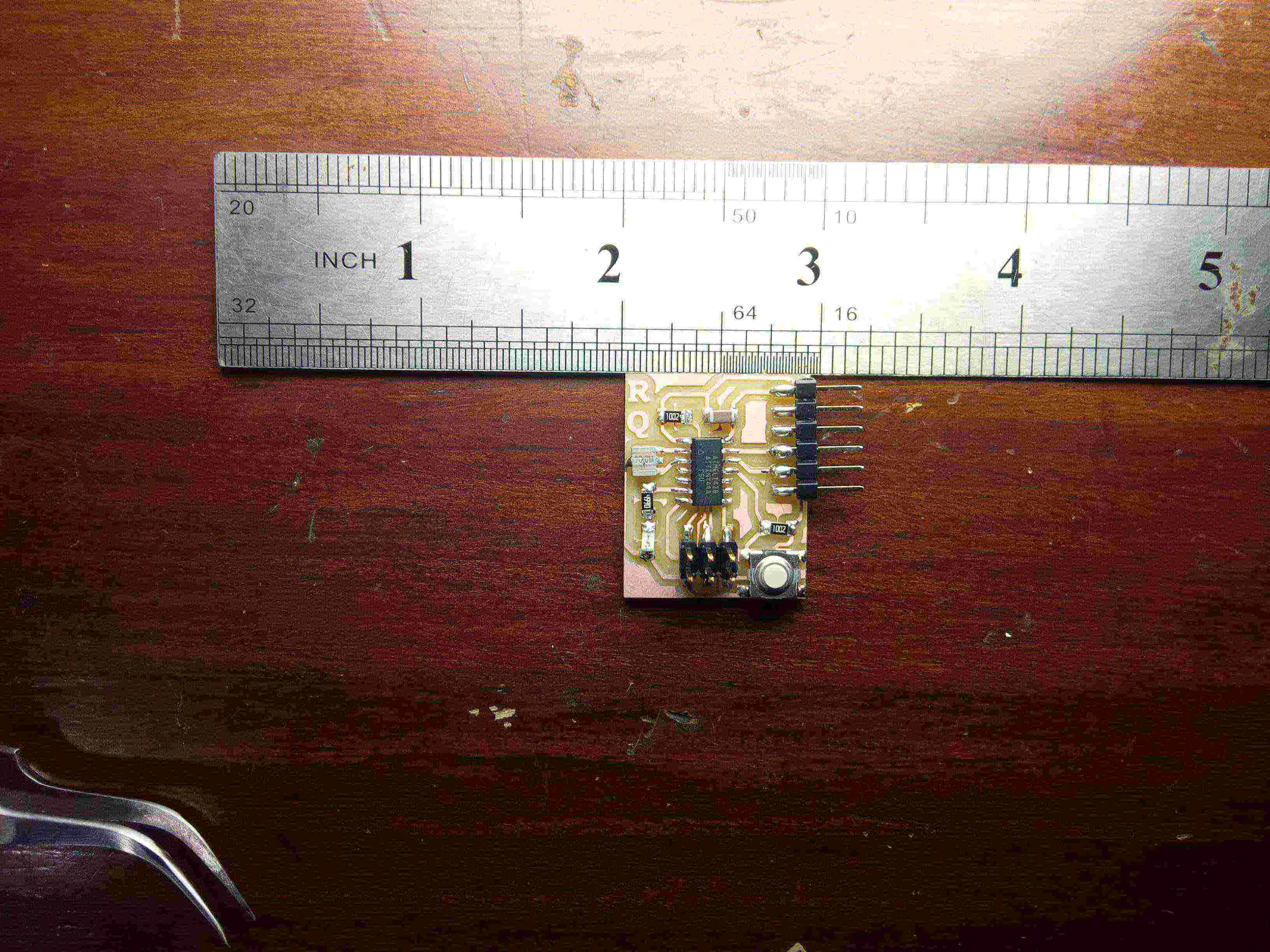 Final picture of my circuit, showing its size in Inches
« Week6
Week8 »
Final picture of my circuit, showing its size in Inches
« Week6
Week8 »