Assignment 08
- Group assignment: Test runout, alignment, speeds, feeds, and toolpaths for your machine
- Individual assignment: Make something big
Group Assignment:
We are unable to do this week task on time because our ShopBot was not in operational condition, so we complete the work till designing and leave this week task until
Mr. Francisco Sanchez who is in contact with our instructors come to fix the machine, and then suddenly in Week-12 he got the visa to visit Pakistan and came here to rescue our week-8 tasks. Not only how to run ShopBot, we learn many things from him.
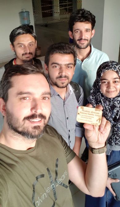 Group Selfie with Mr. Francisco
In group assignment we done 2 things, as our machine is working first time, we need a flat surface platform for it. Second we make a test part which help us to set the size of slots in our Individual Assignments.
- Flattening the Platform
Taking Measurements
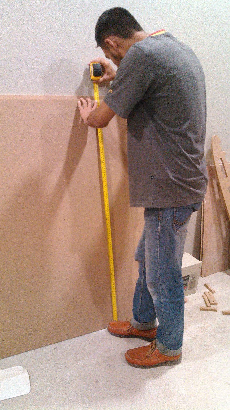
We are provided 8x4 ft 17mm MDF Wood boards for working on this week task,we use MDF board as platform for our Shopbot, but after checking the thickness we found that the board was not 17mm thick on each side.
 Measuring thickness of board
We also measured height and width of the board because while creating toolpath we need to feed these values as well
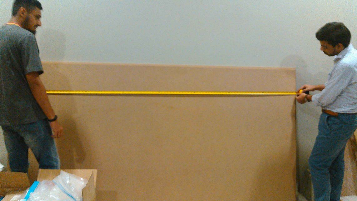
 Taking board measurements
To make the surface flat we are using spoiler board cutter which shaves board to same thickness.
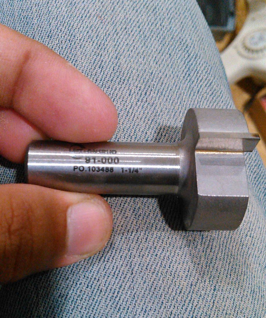 1/4" Spoiler-Board Cutter ( 91-000) Bit
Generating Toolpath:
We are using VCarve Pro Software to generate the G-Code for ShopBot, below we described each step for this process:
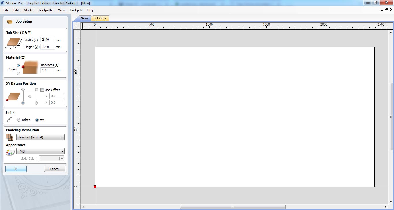
- Double click on VCarve to open it
- Fill the job setup menu by entering board dimensions (width, height and thickness), set the XY Datum Position by clicking on bottom left corner, set units (our dxf files are in millimeter so we select "mm" in this column) and in last for appearence we select MDF because we are using MDF, then click "OK" for file operations.
- To generate a toolpath a vector is required, so we draw rectangle on whole board.
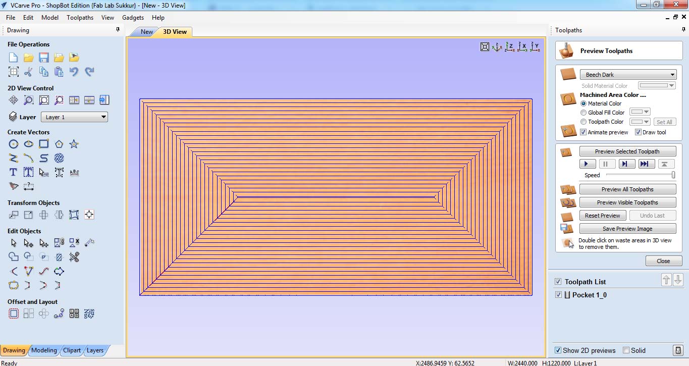
- After making vector now we are setting up the toolpath. Click on "Pocket toolpath" option in toolpath tab, then set the cut depth to "1mm" this shaves the whole board over 1mm, then select the "tool", in our case we select 1/4" Spoil-board cutter (the picture of the tool is mentioned above). Now select the vector, name the toolpath and click on "Calculate"
- After calculate the toolpath it is good practice to check the Preview of toolpath, if something is not shown right then change the settings and again generate toolpath.
- If everything is correct in preview save the toolpath by checking post processor and set it to the dimensions we use to make the file. and then click on "Save Toolpath(s) to File", this can generate .sbp file which is used by ShopBot as instruction to work on job.
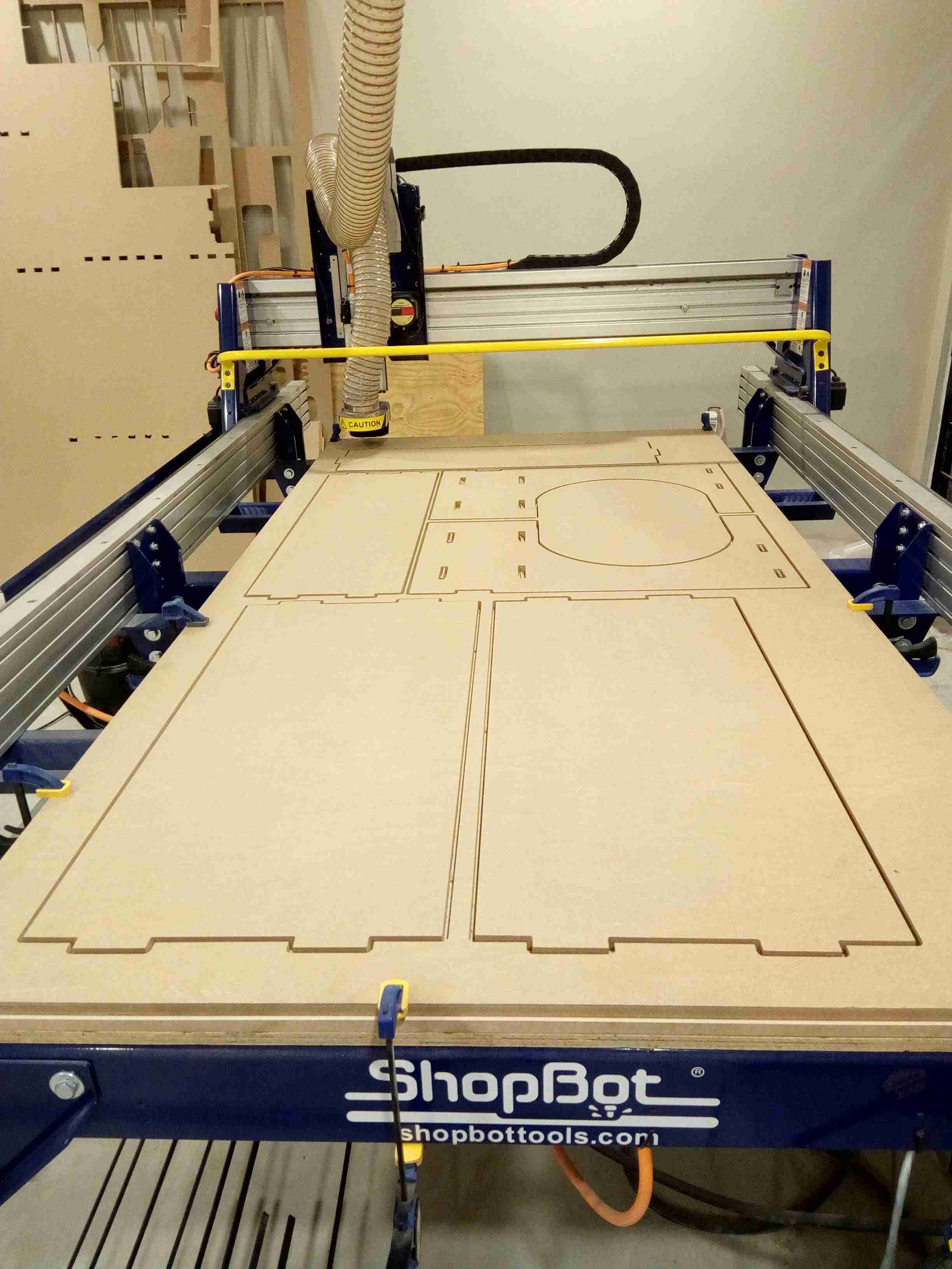
- Generated .sbp file is given to shopbot, after setting x,y and z coordinates, we click on "Cut" in Shopbot panel to start the job
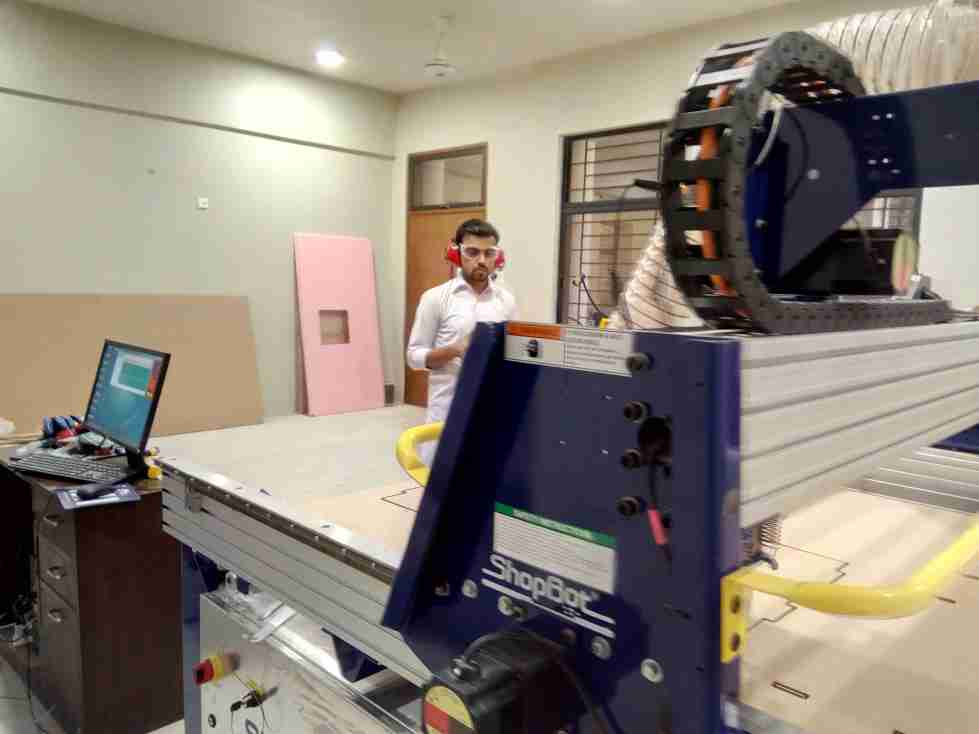
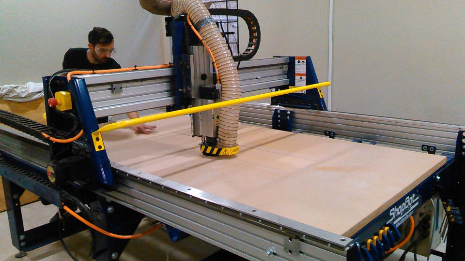 Mr. Francisco checking machine performace while machine is paused between surface flattening process.
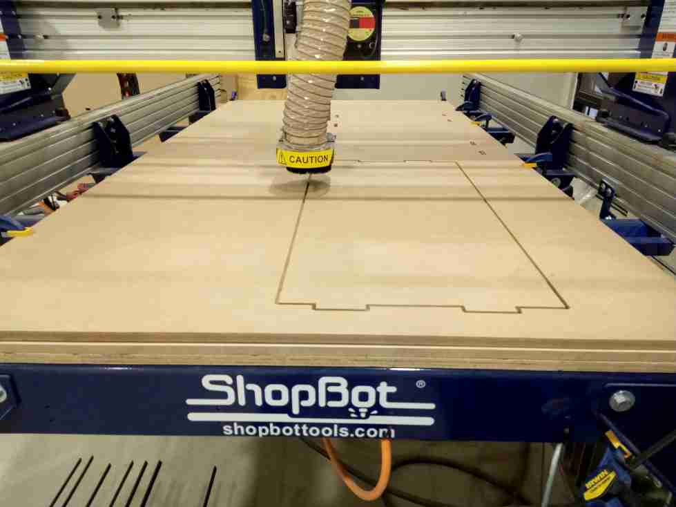
- Making Test Part for Press-Fit
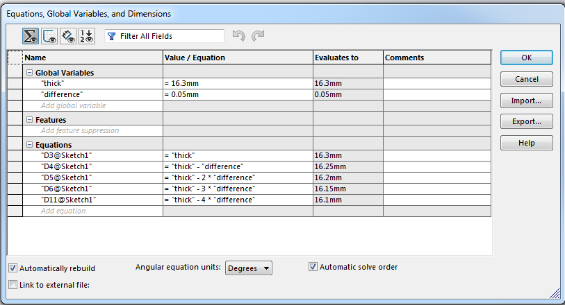
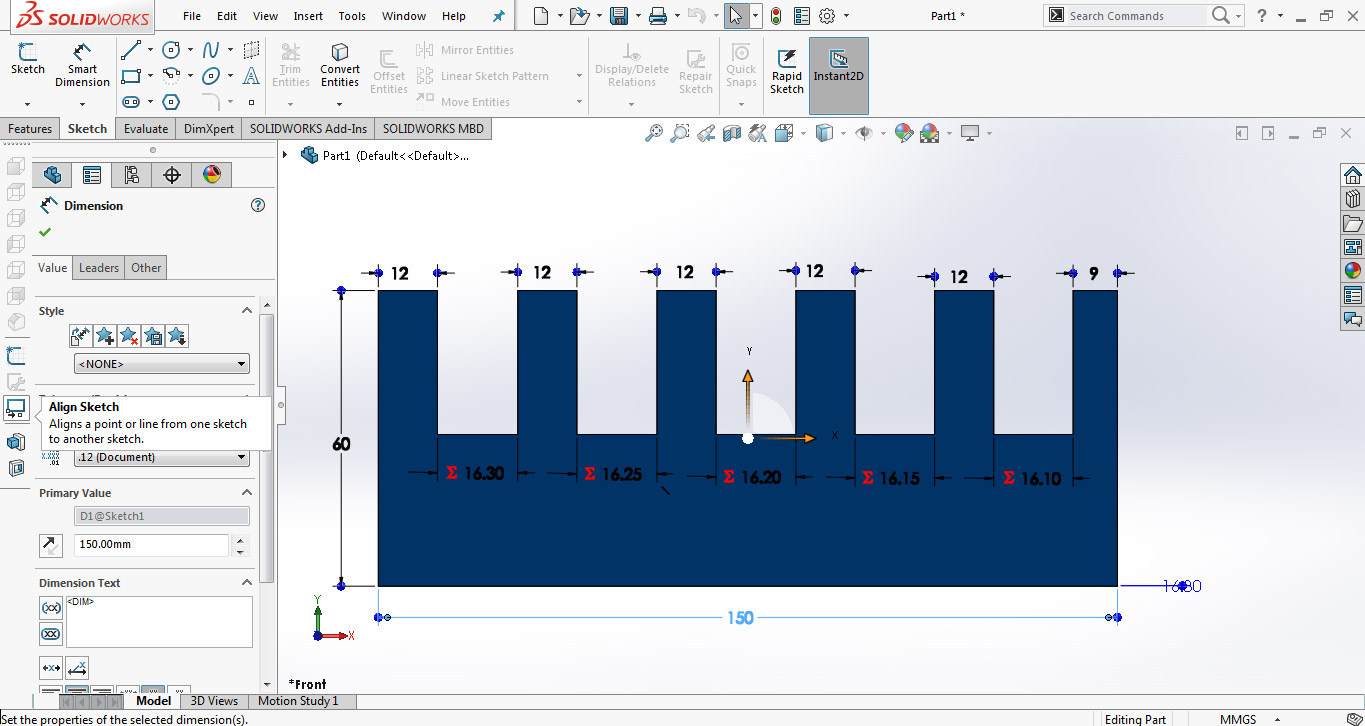
Most of our assignments are press fit so we made a test part with different thickness slots to check in which slot the wood is better press fit. The design is made in SolidWorks while using two parameters, one is average thickness of material and other is the "difference" which is used to set the slot sizes.
Using "Line" tool and "smart dimensions" we made this little piece of 60x150mm.
For VCarve we need a file in .dxf format and to make a dxf in Solidworks first we need to open the file in "drawing" window then save it as .dxf
After making test part design we are instructed to prepare our week assignments and set them along with test part in VCarve for job.
Individual Assignment:
Deciding what to make
When it comes to making something big, there were many different ideas in my mind. I started to search for a few design ideas as well but all I got were designs which were very complex. So I thought to replicate the bench we used to have at our schools in childhood
Designing:
I started designing the model in Solidworks since this assignment must be a parametric one. I first made the individual parts and then joined them using the Assembly portion. While some of the parts were identical so made just one of them and used their copy while assembling the whole model.
After making the individual parts of desk in Solidworks, they look like the pictures given below:
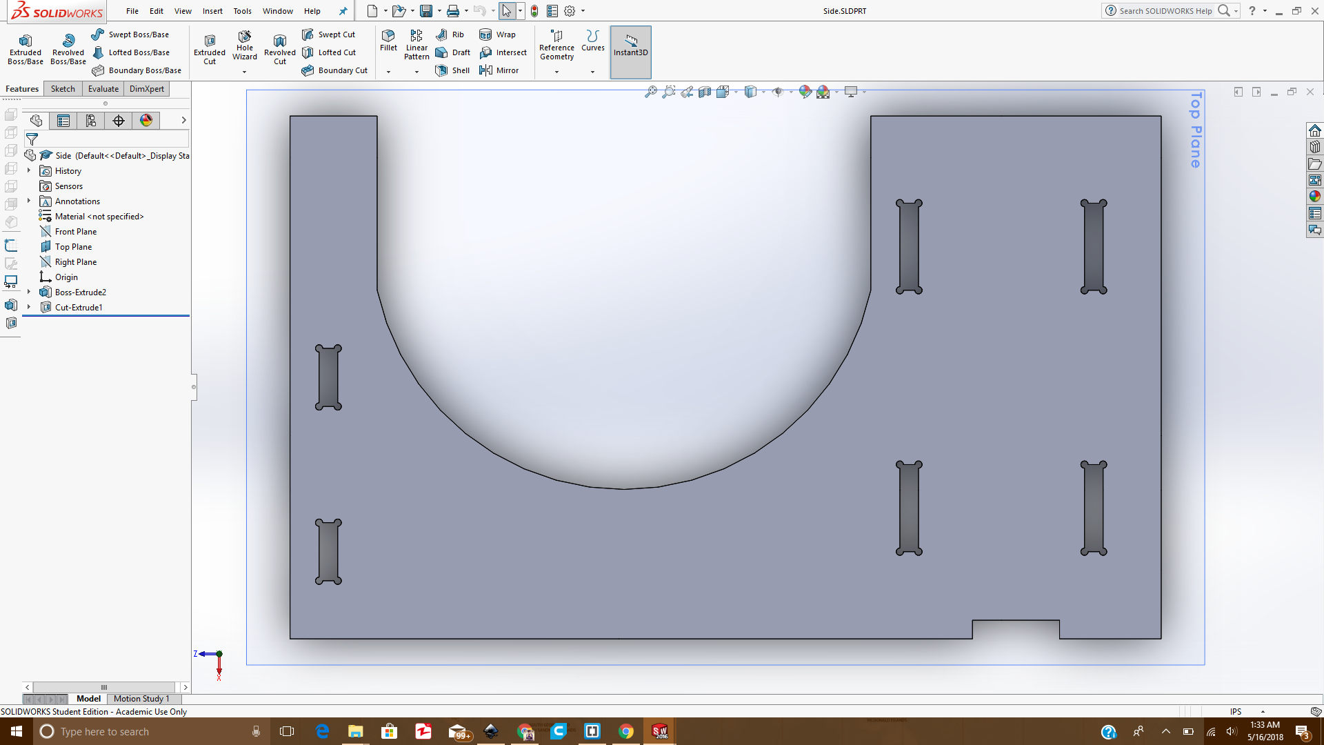 Side of the desk
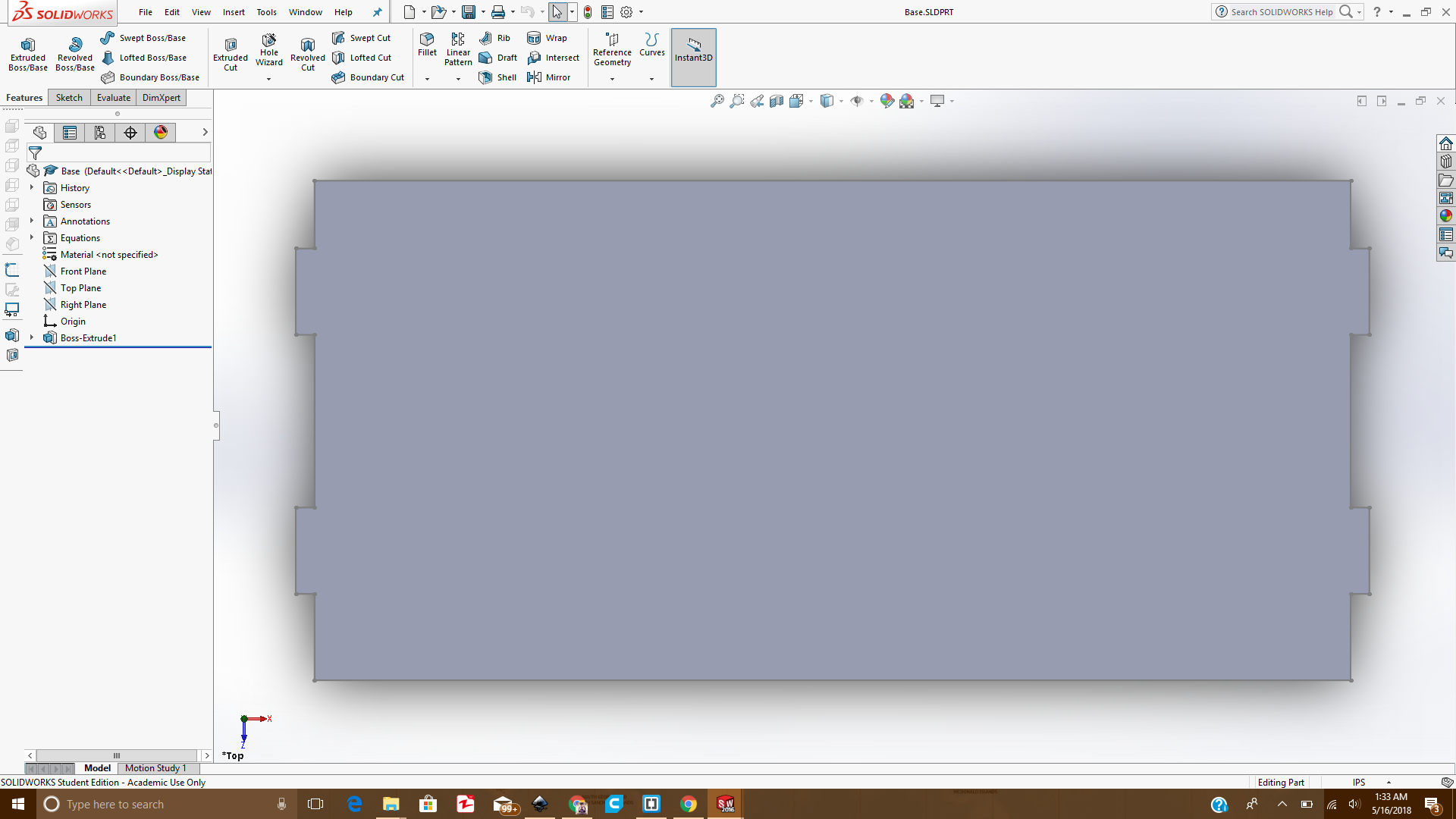 Base of the desk
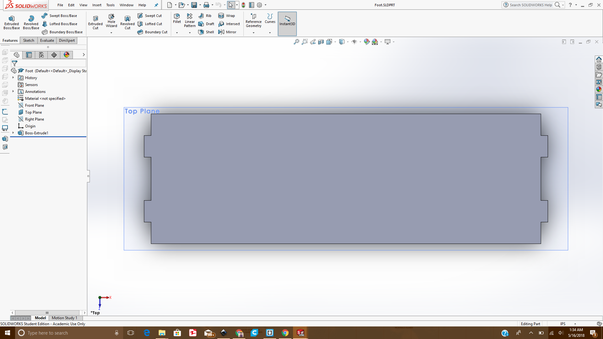 Foot of the desk
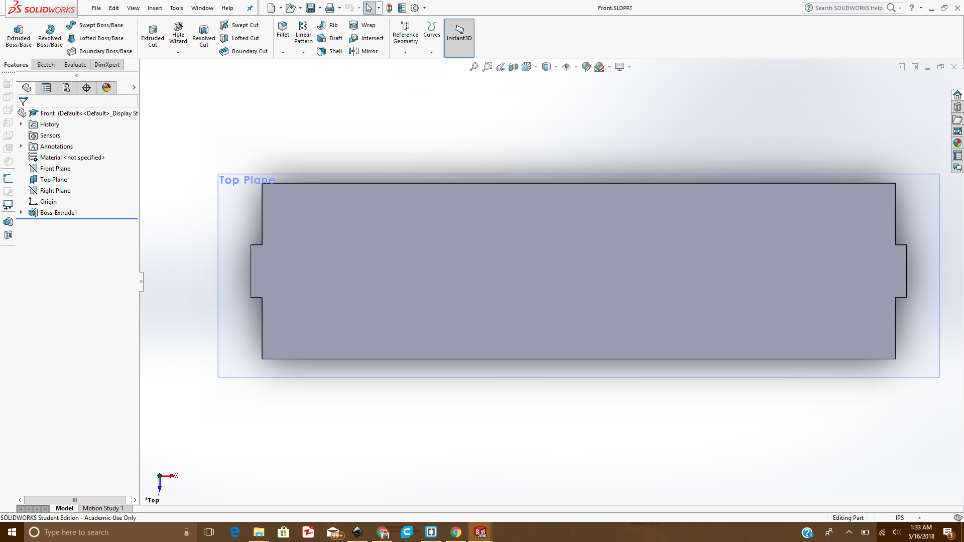 Front of the desk
Once these all parts were combined together, an Assembly or a complete 3D design was made. That design is shown below:
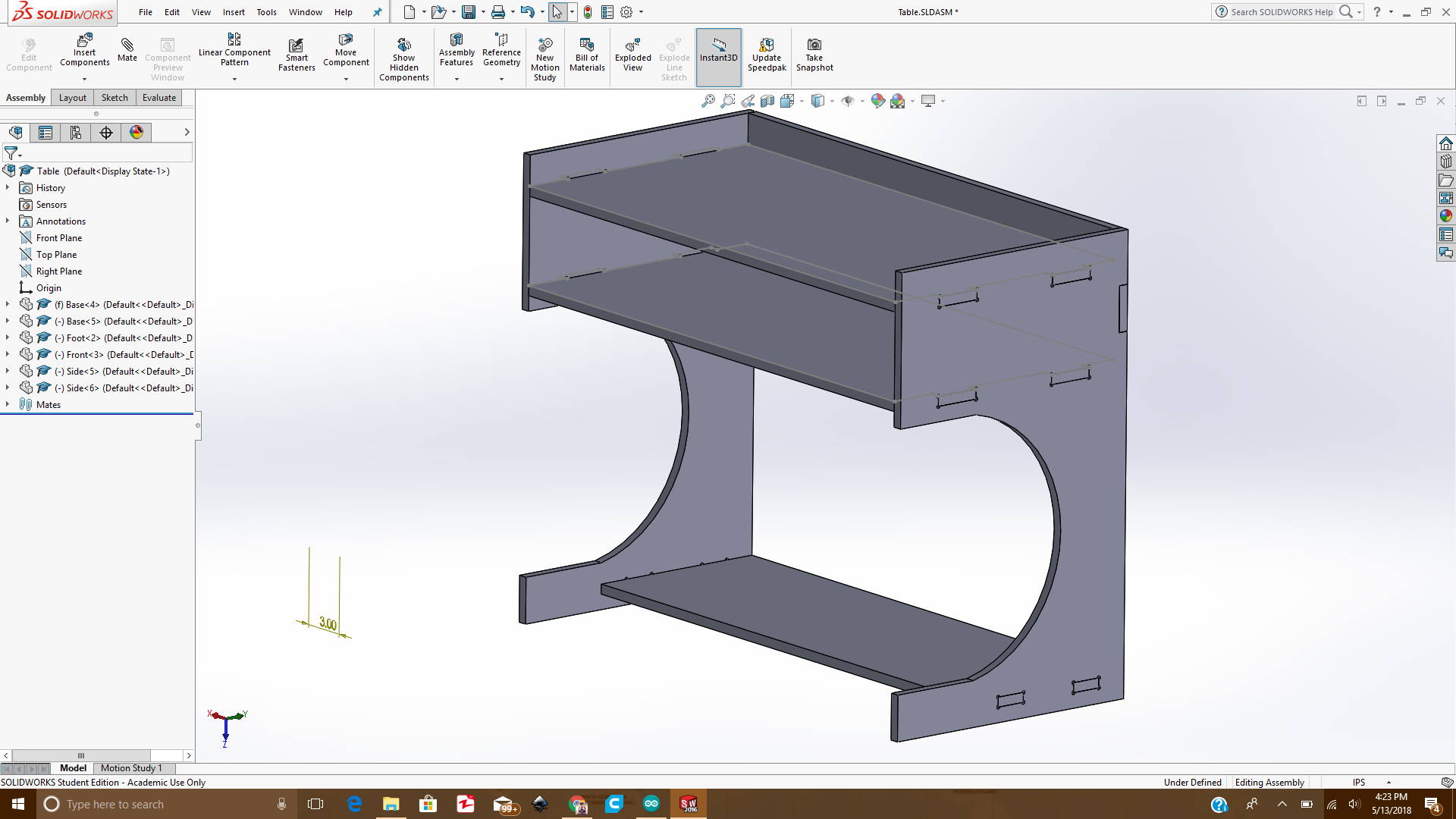 Assembled desk in Solidworks
then from the assembly I generated a .dxf file so that I can use it to cut the design.
 Parts arranged in a DXF file
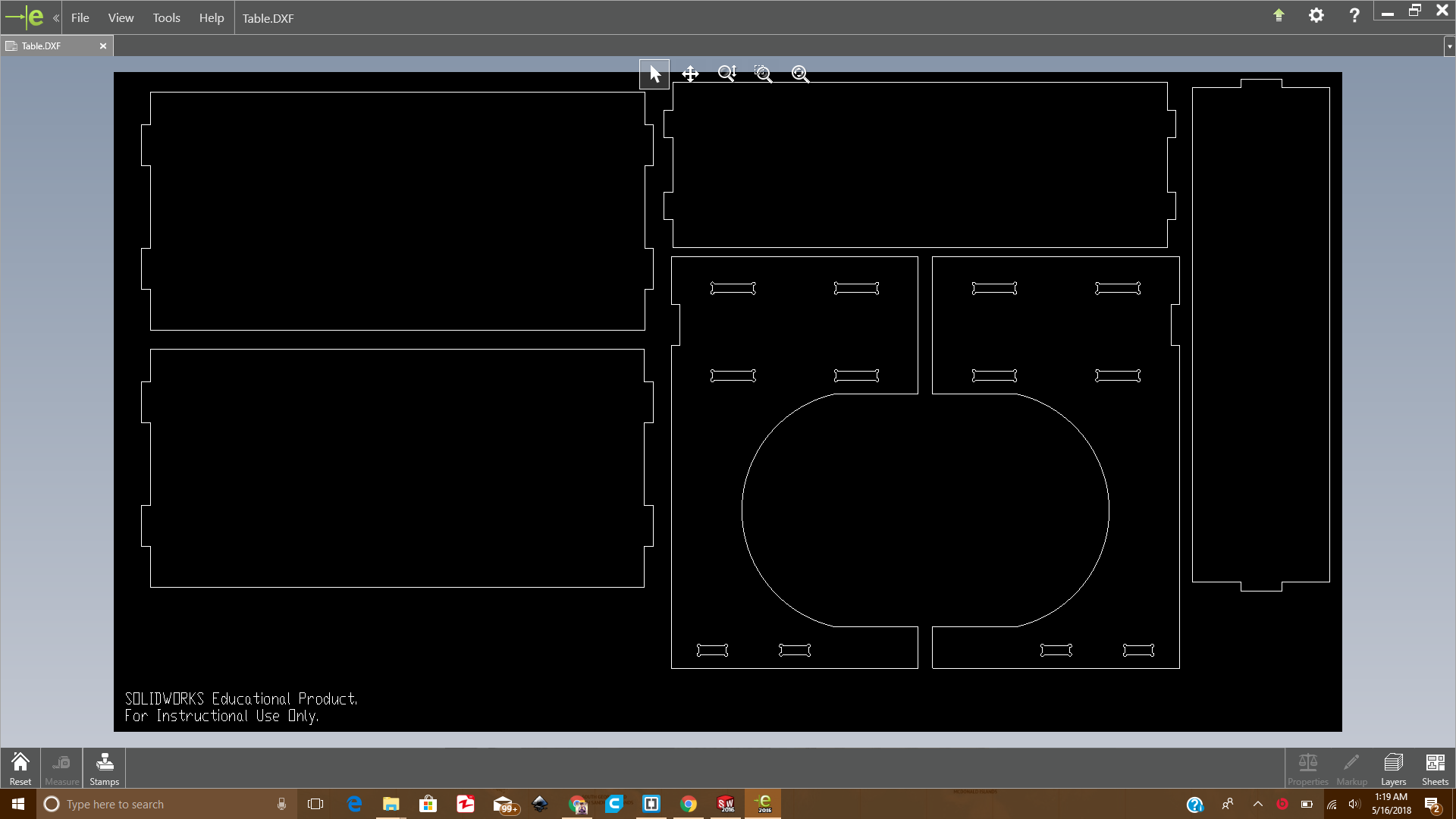
Inorder to check that the design is fitting properly, first i need to cut the model on cardboard to see if it's okay or not. For that I opened the .dxf file in Inkscape software, the design was initially too large since it was made for cutting in Shopbot as shown below:
 dxf imported in Inkscape with actual dimensions
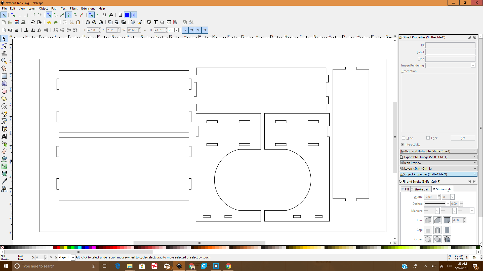
Now I scaled down the design in Inkscape with a scaling factor such that the thickness I selected of the MDF material(16.3mm) shall be reduced to the thickness of cardboard(4mm) I am using right now, and the value of scaling factor came out to be 24.53% and I scaled the design accordingly as shown below:
 dxf after scaling in Inkscape
Then I proceed to the Laser cutting, and the pictures during and after laser cutting are given below:
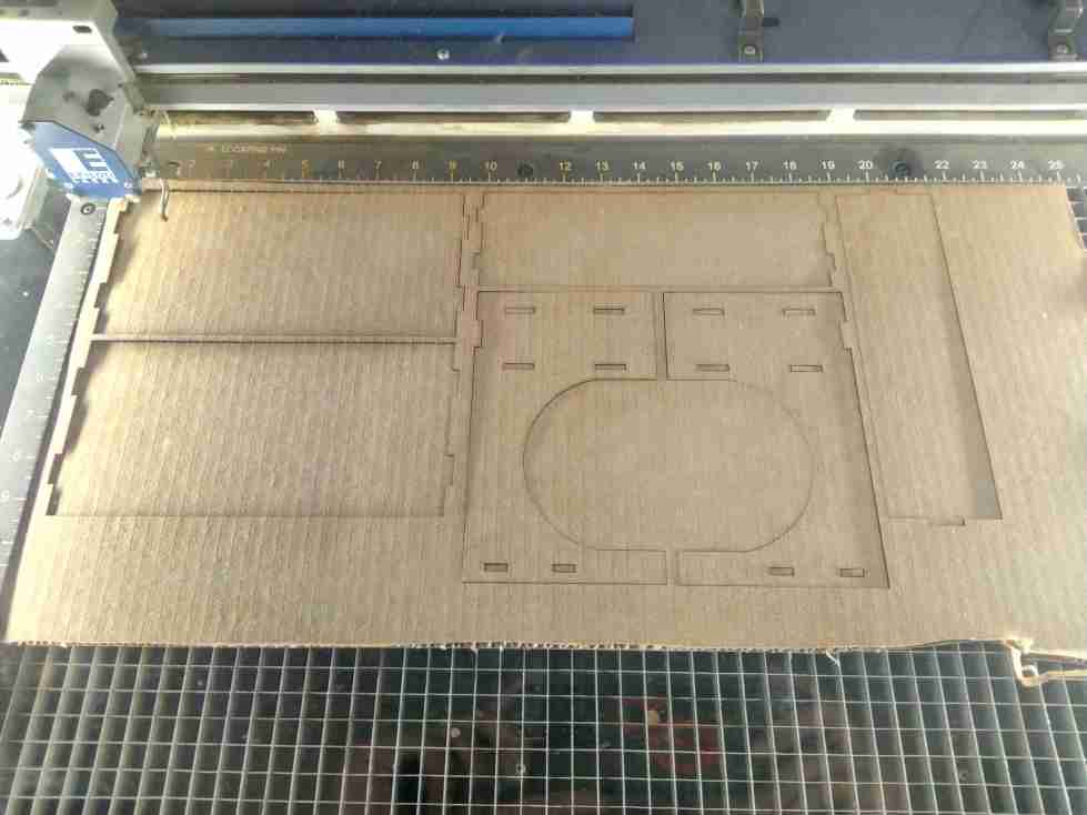 During Laser cutting
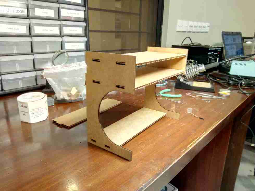 After laser cutting and Assembling
After that I opened the Vcarve software and imported the pdf file which I exported from the Inkscape. Then I sepereated the components according to layers and toolpaths i.e Inside and Outside as shown below:
 Seperating components accroding to Layer
Then I selected the components on the layer (Inside and Outside) and generated and saved their toolpaths as shown below:
 Toolpath generation
Using the .sbp files generated from the Vcarve software, I started cutting the parts. First the Inside layer components and then the outside layer components as given in the pictures:
 Cutting the outside Layer
 While the machine was cutting the Parts
 Once the cutting was done
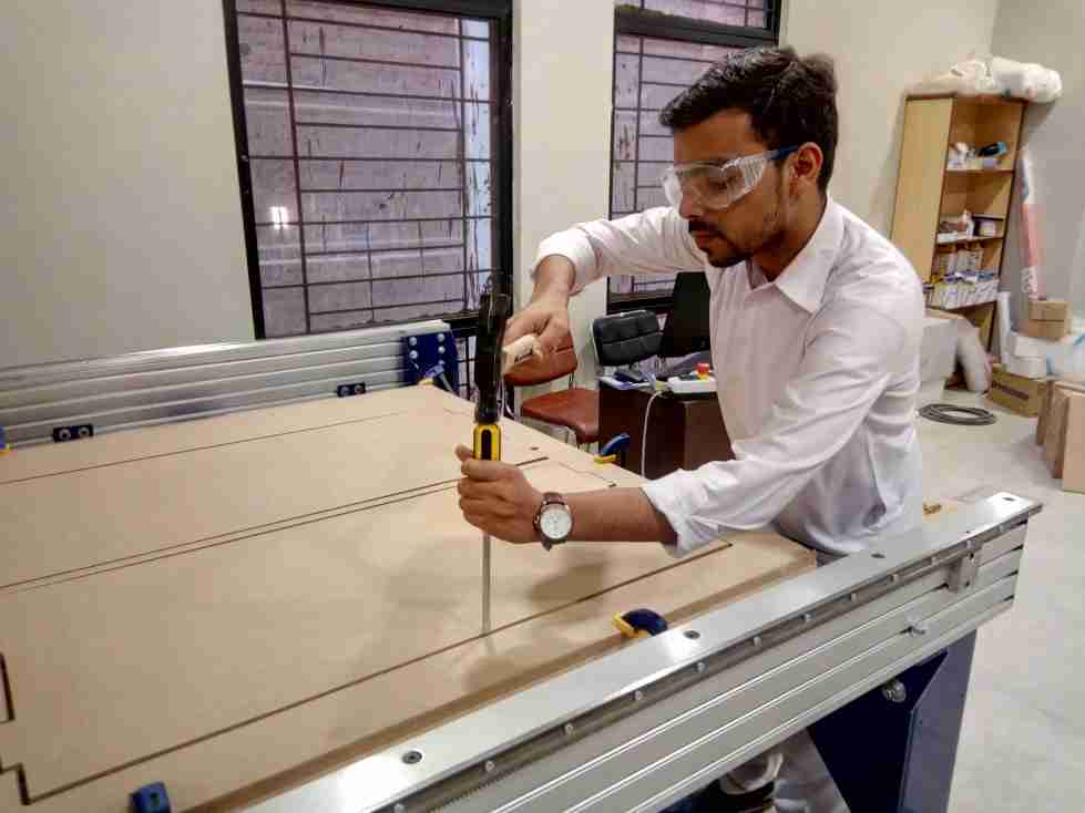 While removing the tabs
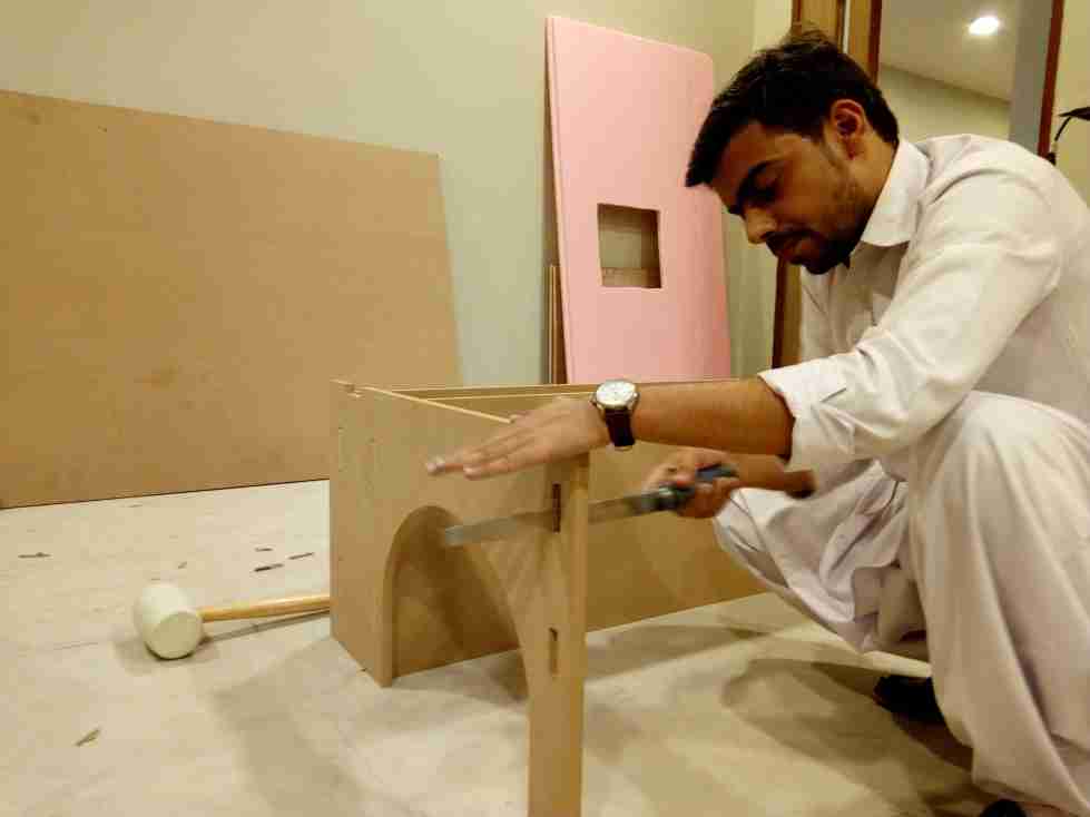 Fixing the parts so that they can pressfit
and Finally the school time memories revoke as the desk was made :)
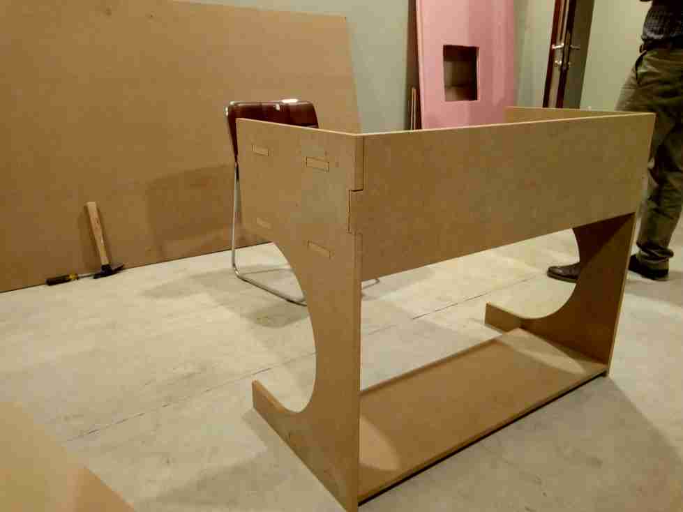 Final result of the week8
All the Files of Week 8 can be downloaded from Here.
« Week7
Week9 »
Final result of the week8
All the Files of Week 8 can be downloaded from Here.
« Week7
Week9 »