

RISC (Reduced Instruction Set Computer) performs more instructions with lower cycles as compared to CISC architectures. CISC processors include the Intel x86 and 8051, Motorola 68000 and Zilog Z80 families.One of the key advantages to RISC is the load/store architecture which separates memory access and ALU operations (arithmetic logic unit). This improves cost, power consumption and heat dissipation, making them desirable for light, battery operated devices. RISC processors can be found in the ARM, AVR and PIC microcontrollers.
AVR is a family of microcontrollers developed by Atmel that use the RISC processors. AVR are most commonly used in the Arduino line of open source board designs. These are available in 8-bit tinyAVR, megaAVR and XMEGA. AVR32 is the 32-bit offering, which was intended to compete with ARM processors. These are not compatible with the original ARM and include additional SIMD and DSP instructions as well as audio and video processing features. One of the nice features of most AVR models is that they can reserve a bootloader region to store re-programming code. The code can then re-program through any interface available.
PIC stands for Peripheral Interface Controller. It is a family of microcontrollers developed by Microchip with a wide variety of options available. They are not strictly RISC processors as they differ very slightly in their operation. The product range includes the 8-bit PIC10, PIC12, PIC 16 and PIC18, the 16-bit PIC24 and dsPIC and the 32-bit PIC32MX, PIC32MZ, PIC32MM and PIC32MK. The 8-bit range focuses on lower cost, the dsPIC focuses on digital signal processing. The PIC32 series of microcontrollers uses the MIPS32-M4K core technology, which is a 32-bit RISC architecture. MIPS is a direct competitor to the ARM processors covering all types of applications in home entertainment, embedded and networking products, mobile, wearable and IoT devices.
The Intel MCS-51 (also known as 8051) is a CISC architecture. These are available in 8-bit, 16-bit and 32-bit microcontrollers. 8051 silicon IP cores are typically smaller size, lower power compared to ARM Cortex-M and MIPS processors. They are used in everything from USB flash drives to washing machines and complex wireless communications systems-on-chip
The purpose of reading the datasheet is to know your Microcontroller. Before starting to work over any device you must know its features, limitations, benefits and many other qualities. The datasheet of ATtiny 44 can be downloaded from Here.
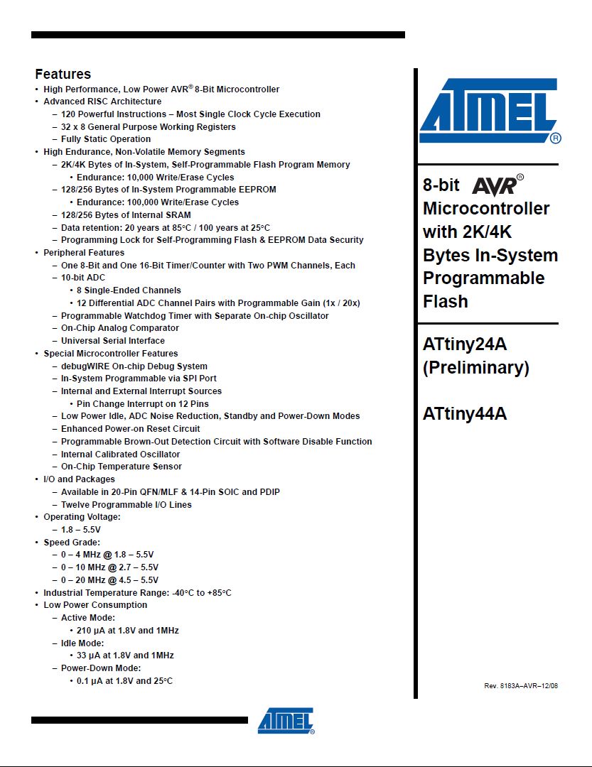
Initially, you may find it very lengthy and tough task to read the datasheet of any device, but you can avoid it by going to information that is important from your perspective as a programmer. Hence the images below are showing the features and pin configuration of ATtiny44.
From features, we came to know about many things, few of them are:
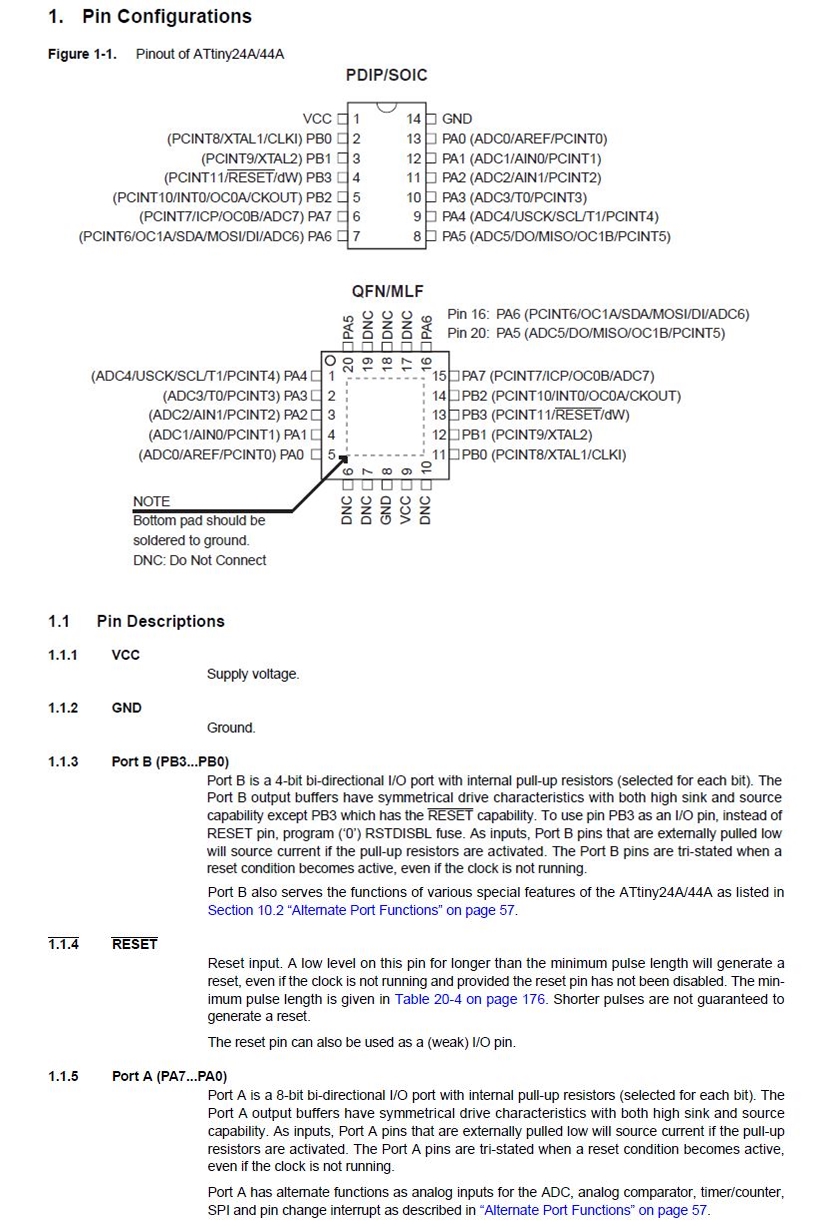
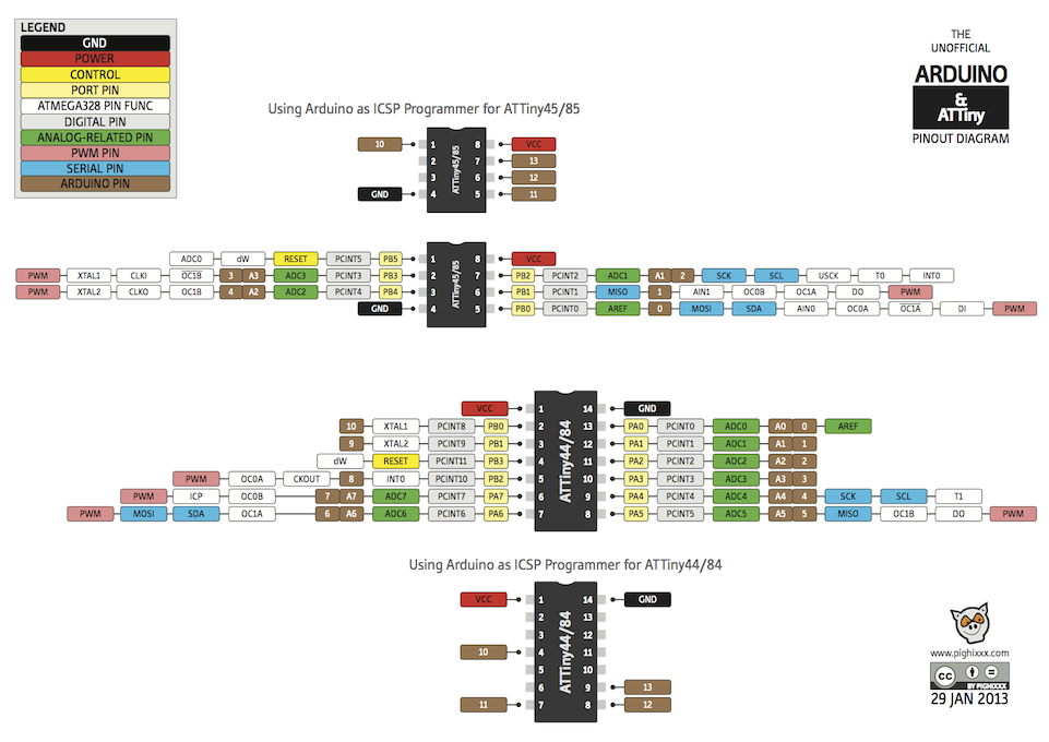
Another important thing about a chip while programming it is to know its "Pin Configuration". Without this information you may not be able to know where your I/O devices are connected. Pin configuration can be seen below:
Inorder to program your board using Arduino IDE, first you have to perform following steps so that the IDE can detect your board:
After configuration of my board, I uploaded the blink file from "Examples" available in Arduino IDE. Steps for that are mentioned, shown below and the results as well:
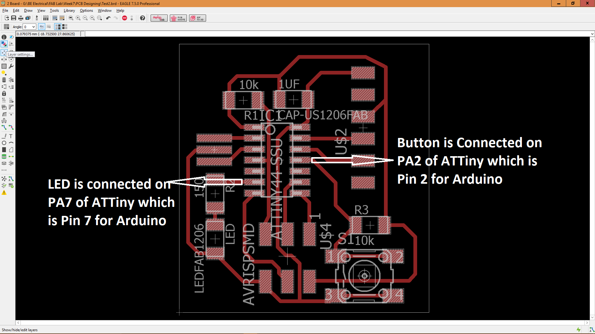
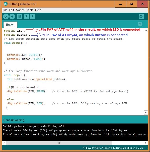
Once the board started working properly, now i uploaded another program to check whether the button connected to circuit is working properly or not. The program uploaded is shown below:
The board can be seen operating using the button in the GIF below:
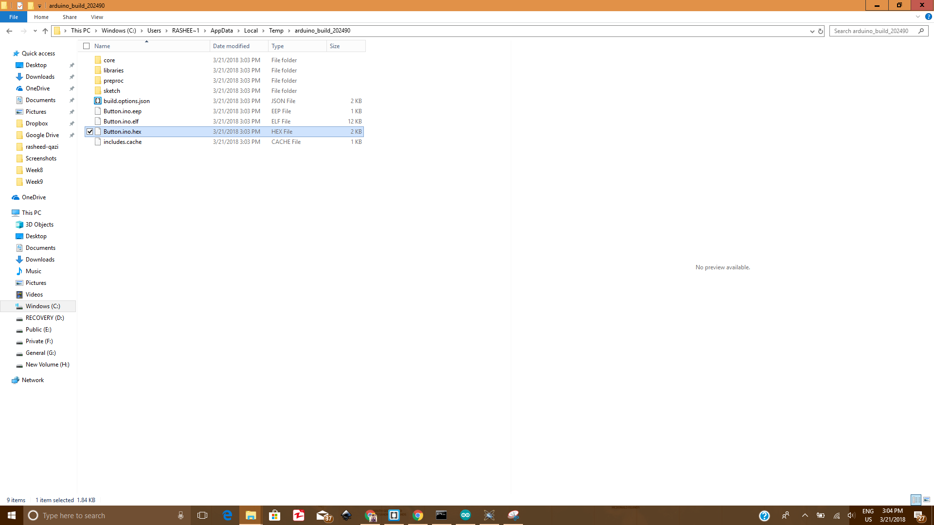
The .hex file for this program can be saved from temporary files if needed. I copied it so that i can burn it later using another software.
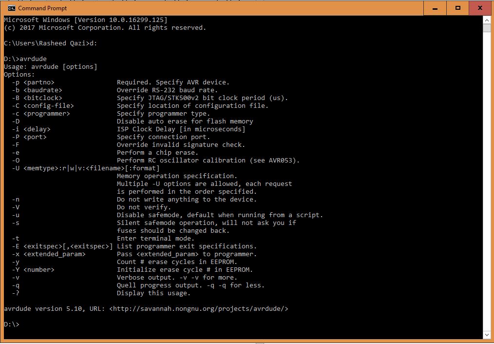
To check whether avrdude is installed successfully or not, go to "Command Prompt" and then to repective drive and write avrdude. If it is installed properly then you will have the following results in your command window:
Now we will upload the .hex file that we copied previously from temporary files to the board using avr dude. For that we will first go to the directory where that hex file is copied using the "cd" and the complete directory address of that location. In my case that address is "G:\BE Electrical\FAB Lab\Week9".
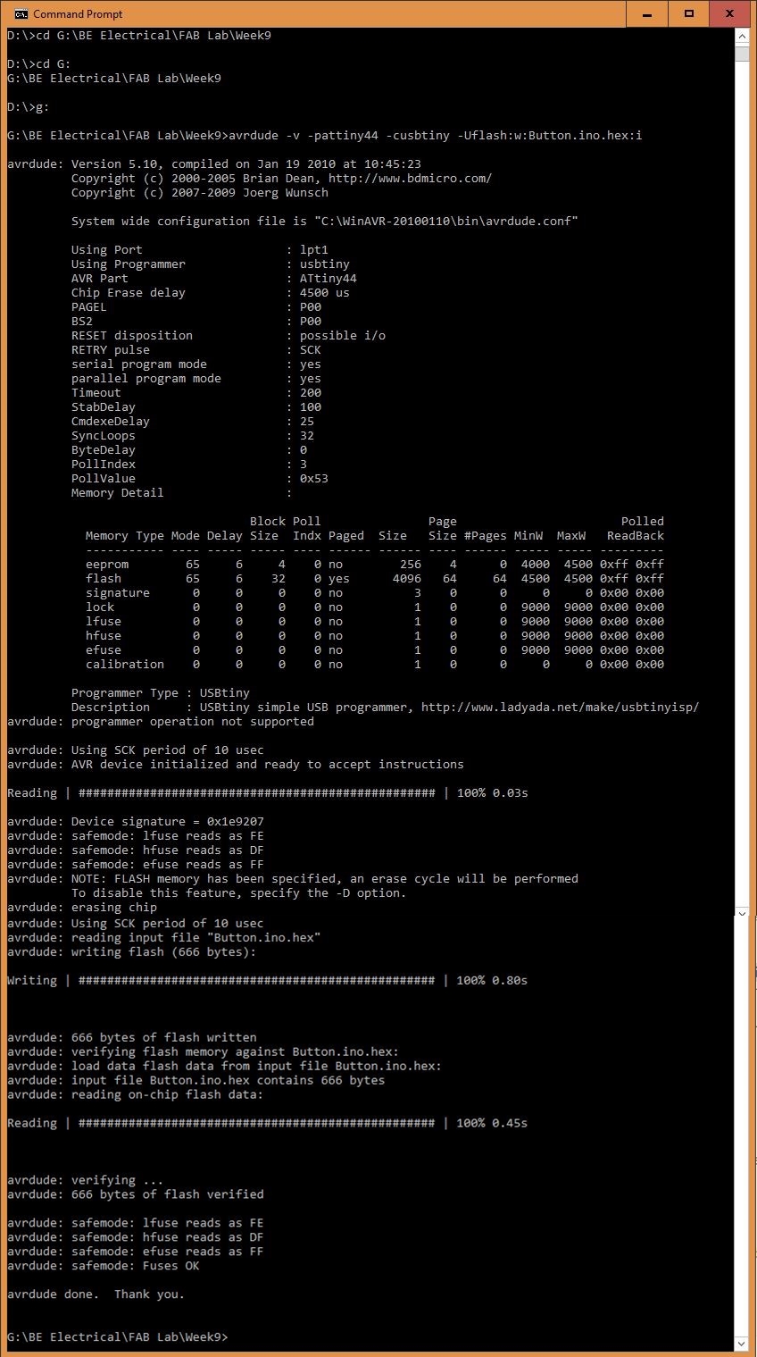
Since i am using ATtiny and my ISP programmer so i have used this (avrdude -v -pattiny44 -cusbtiny -Uflash:w:Button.ino.hex:i) command to upload the .hex file to the controller. You can also use this command if you are using these components as well.
After writing the above mentioned commands you will have the results shown below, which means that you have successfully uploaded the code to your board using avrdude.
The results of uploading hex file using avrdude can be seen in the video mentioned below:
