Mechanical Design
- - Design a machine that includes mechanism+actuation+automation.
- - Build the mechanical parts and operate it manually.
- - Actuate and automate your machine.
- - Document the group project and your individual contribution.
Inspiration
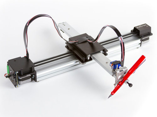
When developing the design of the machine we were inspired by the Axidraw Drawing Machine. This machine consist in two axis being the Y axis fixed to the X one. The aim was to design a 2-axis machine that could then hold a pen or knife to draw or cut vinyls.
Creating the stages in Rhino
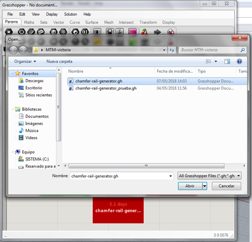
In order to design this machine we used Fellesverkstedet repository, downloading the chamferail grasshoper axis generator.
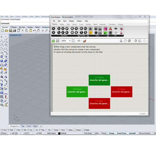
We opened the Grasshopper in Rhino by typing in the command. Then we went to File->OpenFile and a window opened to select the Grasshopper file.
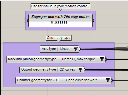
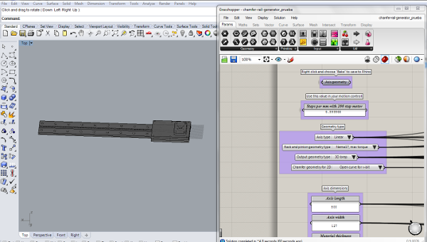
This tool allows you to costume the axis in order to fit our specifications. First thing we did was:
- - Select the Axis type: linear
- - Select the motor that we will be using: Nema 17
- - Select v-bit tool to do the chamfer
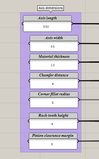
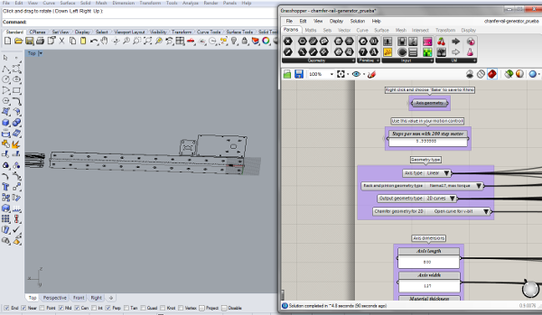
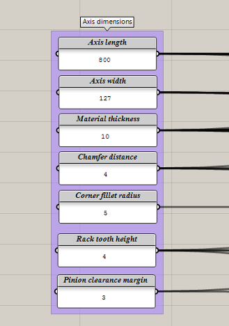
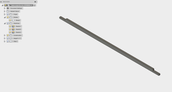
Then we need to specify the dimensions of the axis, in this case we were doing the Y axis. This size is related to the one given to the X axis which is 600mm. Here we also specify the thickness of the material that we are using:
| Length | 550mm |
|---|---|
| Axis width | 55mm |
| Material thickness: | 10mm |
| Chamfer distance | 4mm |
| Corner fillet radius | 5mm |
| Rack tooth radius | 4mm |
| Pinion clearance margin | 3mm |
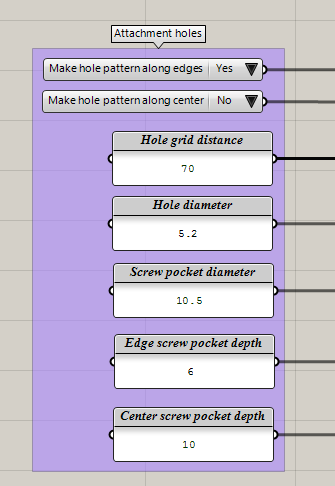
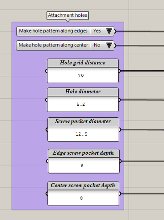
Attachment holes: when creating the stage with the grasshopper we draw this attachment holes but then most of them were removed from the design as we didn't really need them.
| Hole grid distance | 70mm |
|---|---|
| Diameter of the hole | 5.20mm |
| Screw pocket diameter | 10.5 mm |
| Edge screw pocket depth | 6mm |
| Center screw pocket depth | 10mm |
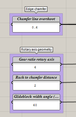
Edge chamfer: these values were left as default.
| Chamfer line overshoot | 0.6 mm |
|---|---|
| Gear ratio rotary axis | 6 mm |
| Rack to changer distance | 2 mm |
| Glideblock width angle | 60 mm |
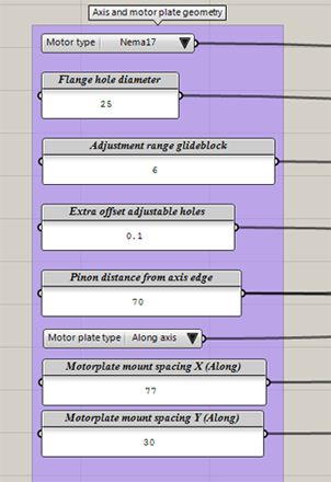
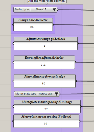
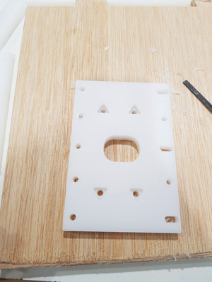
Axis and motor plate geometry: The motor support size was constraint by the size of the X axis. This support needed to fit on top of the X axis to be able to attach them.
| Flange hole diameter | 25 mm |
|---|---|
| Adjustment range glideblock | 6 mm |
| Extra offset adjustable holes | 0.1 mm |
| Pinion distance from axis edge | 70 mm |
| Motorplate mount spacing X (along) | 77 mm |
| Motorplate mount spacing Y (along) | 30 mm |
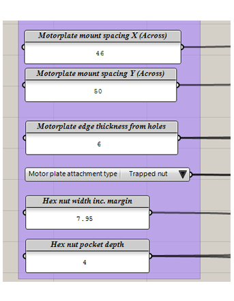
| Motorplate mount spacing X (Across) | 46 mm |
| Motorplate mount spacing Y (Across) | 50 mm |
| Motorplate edge thickness from holes | 6 mm |
| Hex nut with inc. margin | 7.95 mm |
| Hex nut pocket depth | 4 mm |
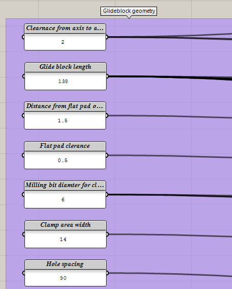
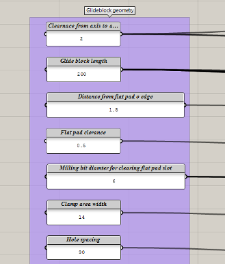
Then we changed the dimensions of the Glide Block as said before we want it to fit in the support of the X axis so we measured what was the length of that piece and changed the length of the Y axis.
| Clearnace from axis | 2 mm |
|---|---|
| Glide block length | 138 mm |
| Distance from flat pad | 1.5 mm |
| Flat pad clearance | 0.5 mm |
| Milling bit diameter for clearance | 6 mm |
| Clamp area width | 14 mm |
| Hole spacing | 90 mm |
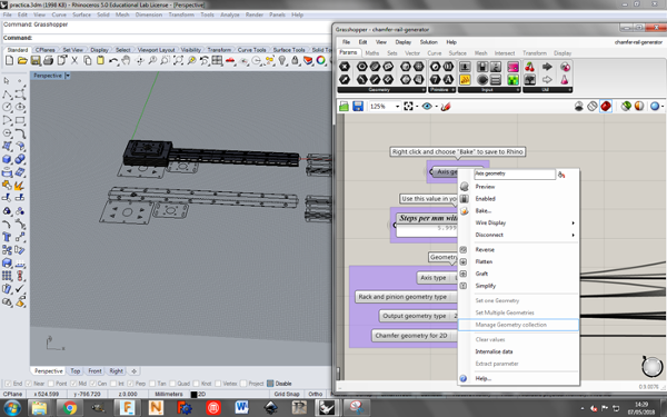
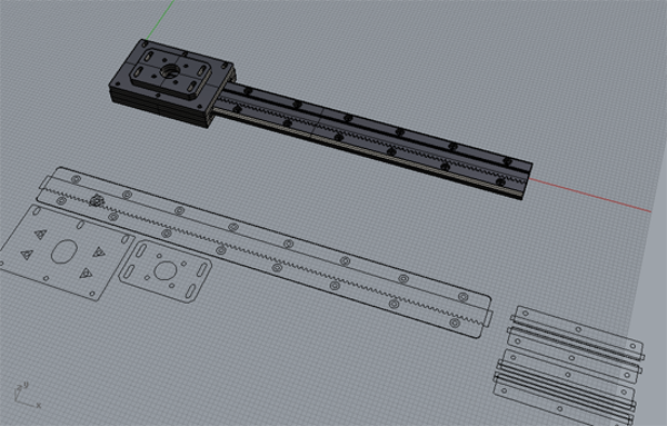
When we finished setting the parameters required for our machine we went back to the top part of the grasshopper file and we right-clicked on the Axis generator, and clicked on Bake.... For doing the 3D we
just needed to change the Output geometry type and repeat the baking process.
X asix
Dimensions:
| Length | 800mm |
|---|---|
| Axis width | 127mm |
| Material thickness: | 10mm |
| Chamfer distance | 4mm |
| Corner fillet radius | 5mm |
| Rack tooth radius | 4mm |
| Pinion clearance margin | 3mm |
Attachment holes:
| Hole grid distance | 70mm |
|---|---|
| Diameter of the hole | 5.20mm |
| Screw pocket diameter | 12.5 mm |
| Edge screw pocket depth | 6mm |
| Center screw pocket depth | 8mm |
Edge chamfer:
| Chamfer line overshoot | 0.6 mm |
|---|---|
| Gear ratio rotary axis | 6 mm |
| Rack to changer distance | 2 mm |
| Glideblock width angle | 60 mm |
Axis and motor plate geometry:
| Flange hole diameter | 25 mm |
|---|---|
| Adjustment range glideblock | 6 mm |
| Extra offset adjustable holes | 0.1 mm |
| Pinion distance from axis edge | 50 mm |
| Motorplate mount spacing X (along) | 77 mm |
| Motorplate mount spacing Y (along) | 40 mm |
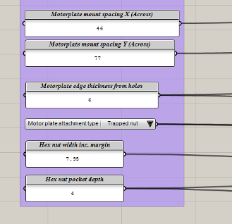
| Motorplate mount spacing X (Across) | 46 mm |
| Motorplate mount spacing Y (Across) | 77 mm |
| Motorplate edge thickness from holes | 6 mm |
| Hex nut with inc. margin | 7.95 mm |
| Hex nut pocket depth | 4 mm |
Glide Block:
| Clearnace from axis | 2 mm |
|---|---|
| Glide block length | 200 mm |
| Distance from flat pad | 1.5 mm |
| Flat pad clearance | 0.5 mm |
| Milling bit diameter for clearance | 6 mm |
| Clamp area width | 14 mm |
| Hole spacing | 90 mm |
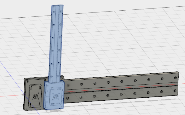
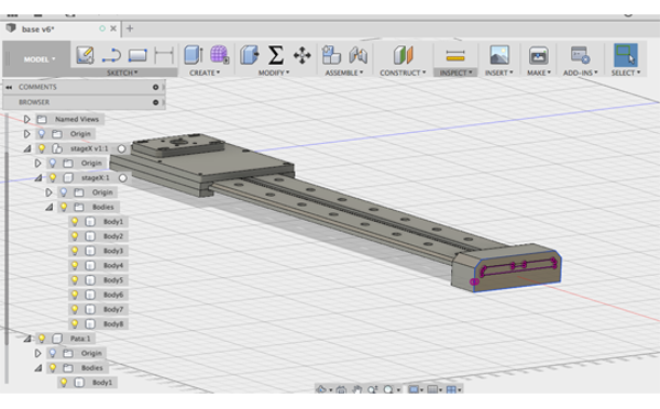
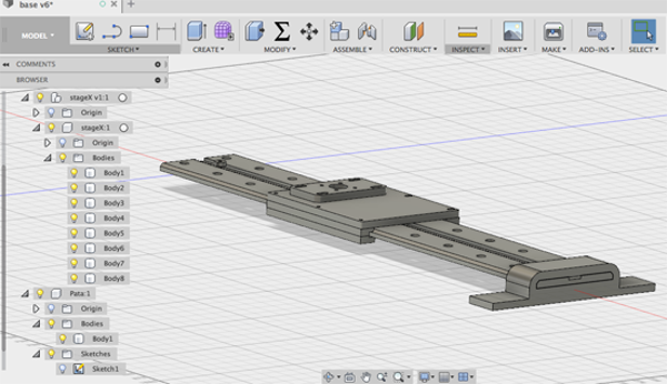
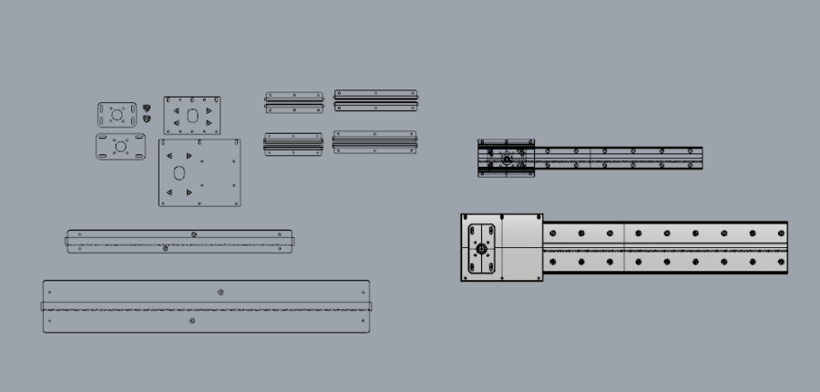
Working in Fusion
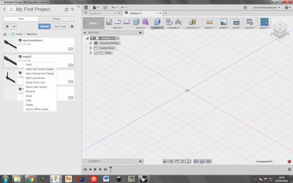
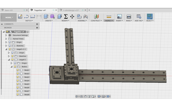
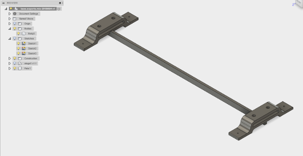
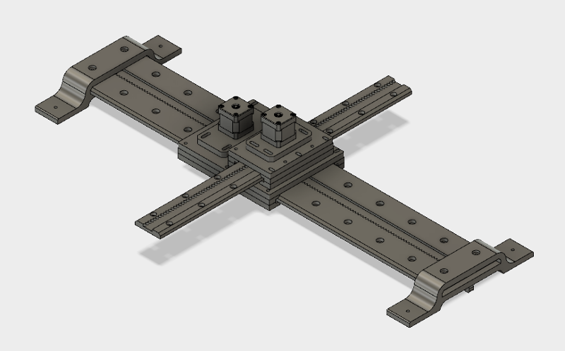
Once we had both designs, we put them together in Fusion 360 to check that the measurements were correct and both pieces fitted in the way we wanted to. We created a new design and we inserted both axis in the current design. Like this if the pieces are modified this design will also change.
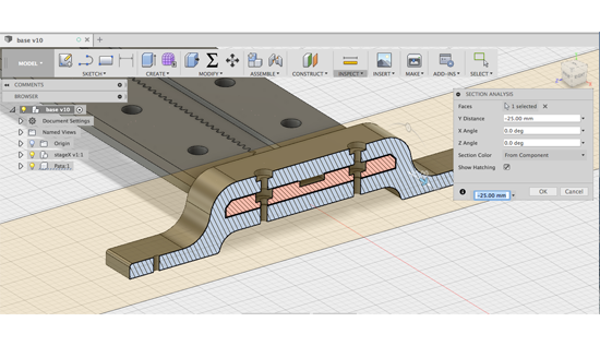
Designing the legs of the machine
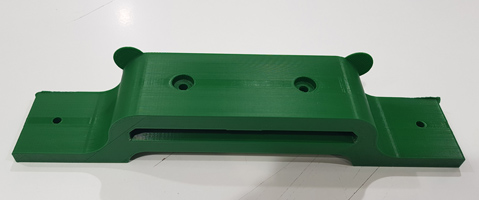
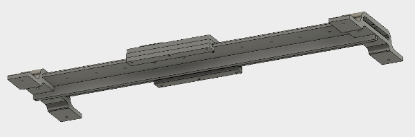
Then we designed the legs that will give support to the machine. The idea is that it can be either attached to a table or to a hung in a wall. For doing so we projected the side of the X stage and as this legs will be 3D printed we created an offset of 0.5mm for tolerance reasons.
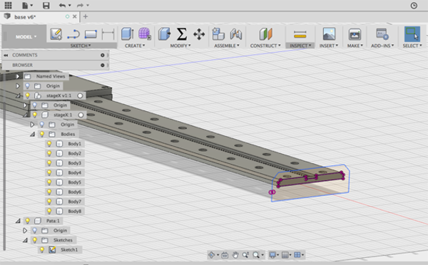
Then we gave the legs a length to be able to put a hole for attachment purposes and then drilled the holes that will allow the union between the axis and the leg. As it can be observed in the picture we removed part of the material from the bottom as we checked how long it will take to 3D print this piece and it was too long. By removing some of this material we lowered down this time.
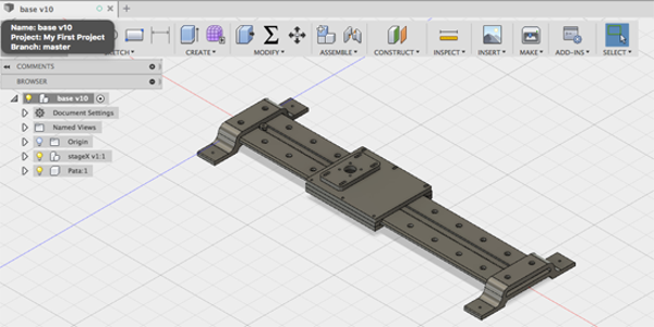
The final design of the X axis with both legs will look like this:
3D printing the legs
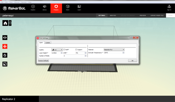
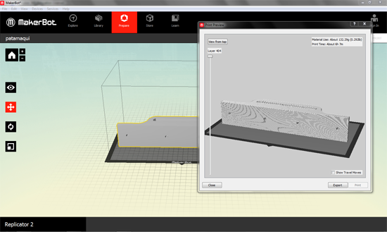
Once the design was done we exported the file as an .stl in Fusion and we opened in Mekerboot's software. To avoid the use of supports we flattened down the figure to one side. The first time we printed the legs we set these parameters:
- - Quality: low
- - Layer height: 0.34 mm
- - Infill: 5%
- - Temperature: 205º
With this settings the estimation of printing time was 3 hours and 30 minutes.
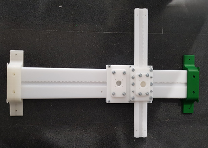
Adding X axis support
After assembly the machine, we saw than the X axis bend a little so we decided to add a piece to support it.
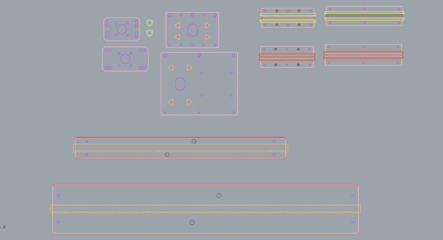
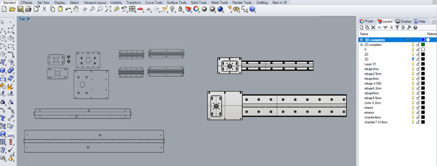
Milling the parts of the machine
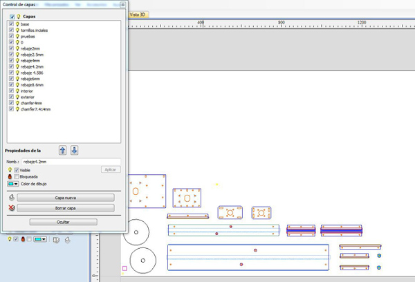
For milling the design we first had to export the .dxf files from Rhino, the 2D files that were generated with the Grasshopper. But before doing so, we needed to separate the pieces that will be milled with different tools (6mm, 3mm and 2mm) in different layers, as well as the different types of cuts (exterior, interior, pockets).
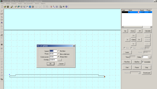
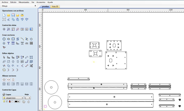
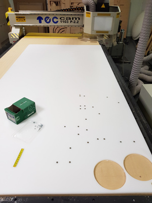
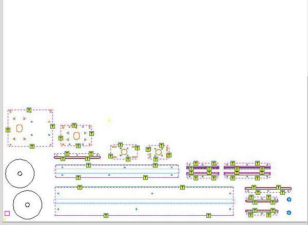
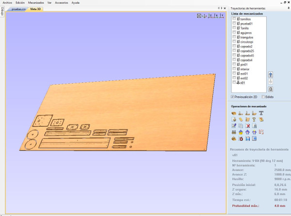
We imported the .dxf file into the CNC software and following the steps of the 8th week:
1. First we checked that we didn't have any open or duplicated vectors.
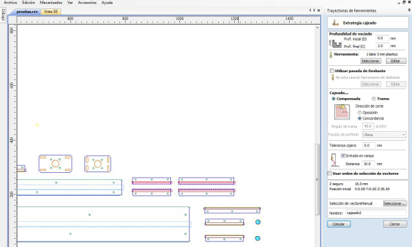
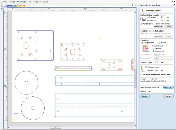
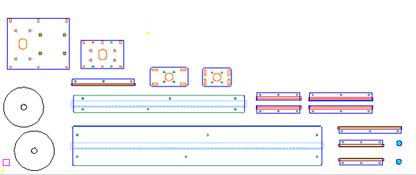
2. Then we started to place the objects to be milled in the material as can be seen in the next picture.
3. Once we finish displaying them we checked that the distances between them were right specially between the ones that we were goind to use the V-bit tool.
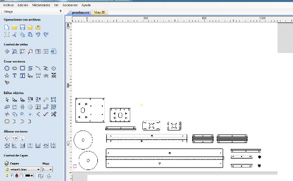
4.To plan the trayectories we splited the different cuts in different layers as was explained before, trying to set them in the order that we were going to mill them.
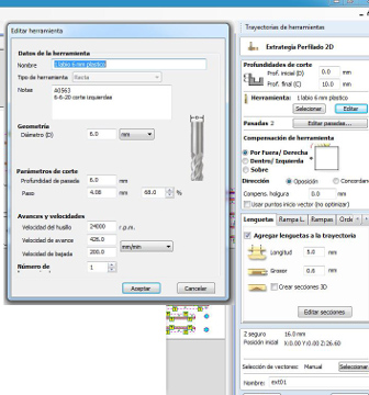
Tools
We used four different tools:
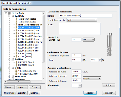
2 mm Endmill Up-Cut double-flute
| Tool diameter | 2 mm |
|---|---|
| Depth of the cut | 1.2 mm |
| Step | 0.8 mm |
| Spindle speed | 18000 r.p.m |
| Feed Rate | 2880 mm/min |
| Plunge Rate | 400 mm/min |
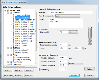
3 mm Endmill Up-Cut single-flute
| Tool diameter | 3 mm |
|---|---|
| Depth of the cut | 3 mm |
| Step | 2.04 mm |
| Spindle speed | 2400 r.p.m |
| Feed Rate | 425 mm/min |
| Plunge Rate | 200 mm/min |
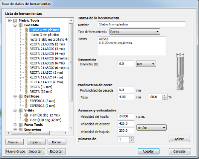
6 mm Endmill Up-Cut single-flute
| Tool diameter | 6 mm |
|---|---|
| Depth of the cut | 6 mm |
| Step | 4.08 mm |
| Spindle speed | 2400 r.p.m |
| Feed Rate | 426 mm/min |
| Plunge Rate | 200 mm/min |
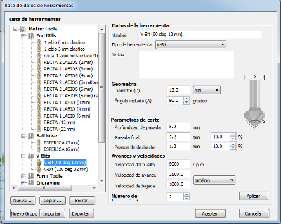
V-bit 90 deg 12 mm
| Tool diameter | 12 mm |
|---|---|
| Angle | 90 º |
| Depth of the cut | 5 mm |
| Final cut | 1.2 mm |
| Roughing cut | 1.2 mm |
| Spindle speed | 9000 r.p.m |
| Feed Rate | 2500 mm/min |
| Plunge Rate | 1000 mm/min |
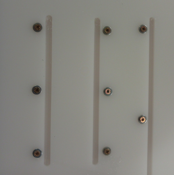
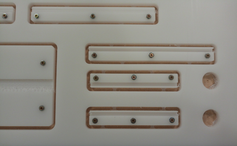
Drilling with 3mm tool:
The first trajectory that we described was the holes as we used them to fix the pieces to the sacrifice layer. As you can see in the pictures we have removed some of them as we were not going to use them.
Fixing the pieces to the sacrifice layer
Pockets with the 3mm tool
We used the 3 mm tool to do the different pockets that we needed for the racket and for covering the nuts. We had two types of pockets that needed to be done one of 2 mm depth and the other one of 4mm depth.
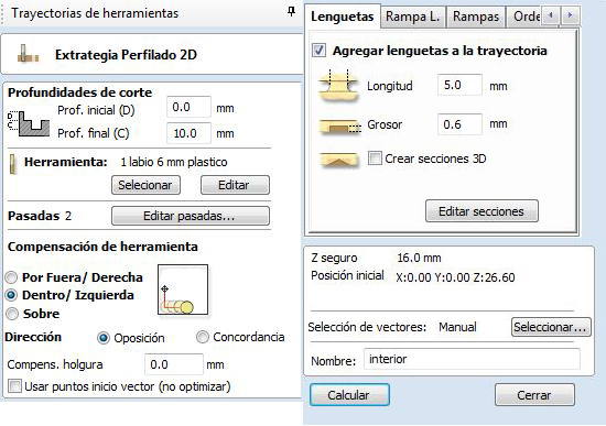
Profile toolpath with the 6mm tool
For millng the exterior of the pieces we used the 6mm tool. We created a new trayectory, setting the outside milling type and selecting the tool that we wanted. Like in the interior case, we used ramps. We selected the exterior parts of all the pieces and we saved this trajectory.
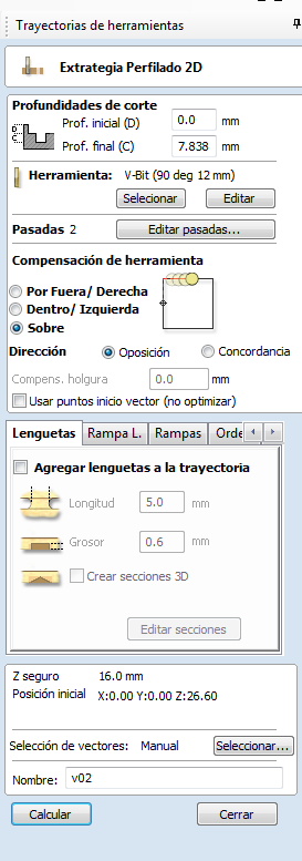
Profile toolpath with the V-Bit tool
To chamfer the sides of the rail and glidebocks.
Milling the pinion with the 2 mm tool
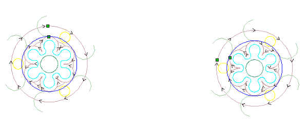
The resulting trayectories looked like this:
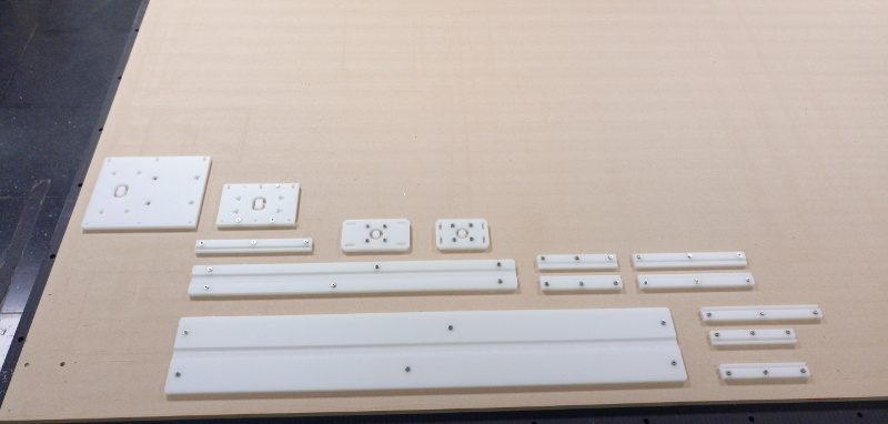
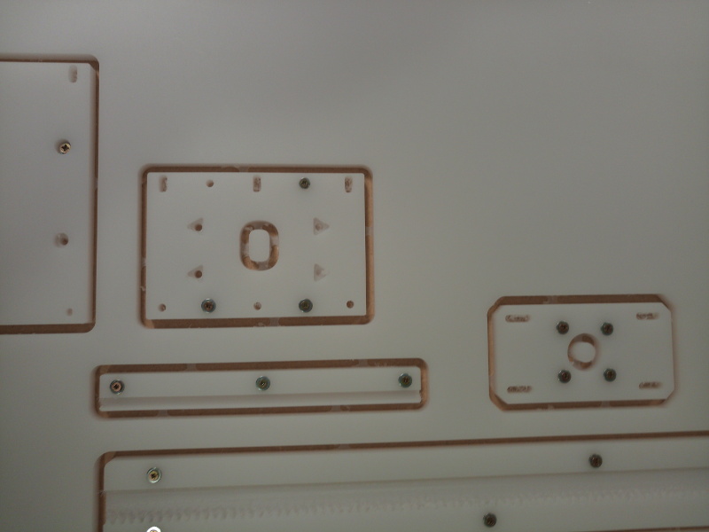
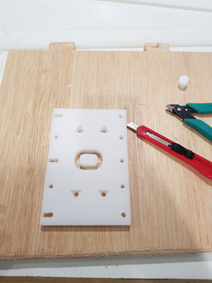
Removing the pieces from the base
Assembly
Once we had milled all the axis pieces we started to assembly them. We had to remove the tabs of some of the pieces:
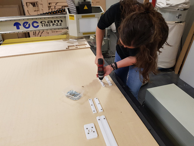
Join the different pieces together
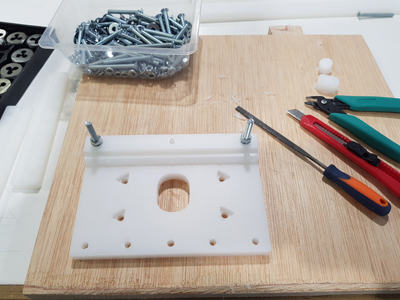
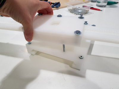
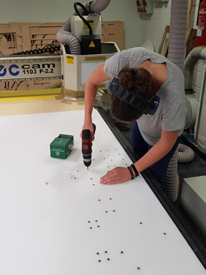
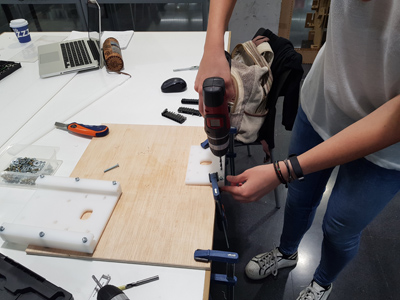
We also did some extra holes that we didn't do when doing the trajectories as they were the ones that conform the union between both axis. We wanted this union to be coiled. First we attached the pieces to be milled manually to the base,
then we drilled the corresponding holes and then we coiled it.
Resulting chamfer rail:
Downloading GRBL firmware
This week we are going to use Arduino CNC Shield to move the machine. This board can move up to 4 step motors: 3 independent axes and one clone axis. We will use Pololu Stepper Drivers.
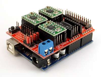
For compiling grbl we followed this wiki tutorial where it explains you the libraries that are required for compiling and uploading the source code into the Arduino Uno.
The grbl libraries can be downloaded here.
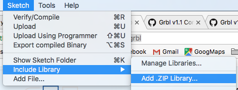
The steps that we needed to do was simply to download that .zip file which contains the libraries, open Arduino's IDE, go to Sketch -> Include library -> Add .ZIP library
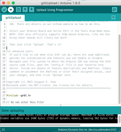
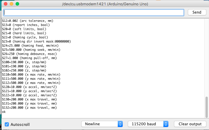
Once we have the library included we go to File -> Examples -> grbl, we open the example, we connected the Arduino board and we uploaded the program.
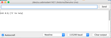
We opened the terminal to check that it was connected, setting to the default baud to 115200.
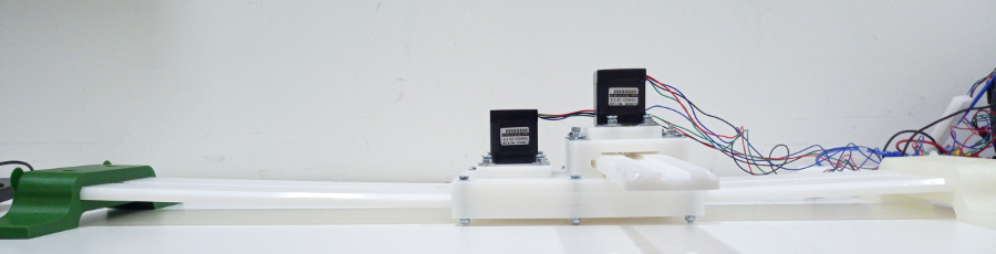
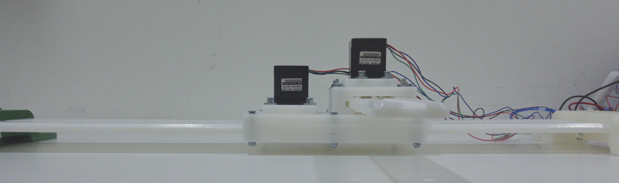
Setting the motor voltage reference
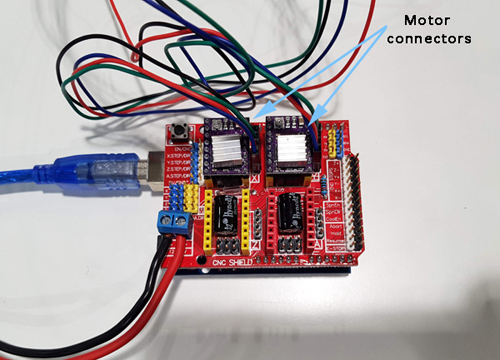
For this machine we are going to be using two Nema 17 motors with two DRV8825 Stepper
Motor Drivers.
- The rated current of the motor is 1.7A.
- The maximum current rating of the driver is 2.2 A per coil.
Taking into account this specifications we are going to set the current limit = 1A, so we now need to calculate the voltage reference required for our motor. This can be done using this equation:
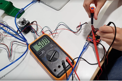
We connected the driver to our GRBL board, the USB connector of the Arduino to the computer and the power supply (at 12V) to the VCC and GND connector of the GRBL board:
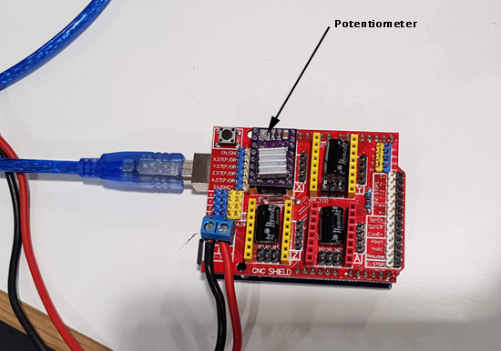
And following this video tutorial we measured with 20V in the multimeter the voltage reference on the top of the potentiometer. We turned the screw until the voltage was less than 2V. Then we changed the multimeter to 2V (to have more precision) and we continued lowering the value down to out goal: 0.5V.
Testing the motors
Before starting to change the different parameters we tested that the motor was working. We opened the serial monitor and we entered G91 G0 X10 and G91 G0 Y10 for both motors to move '10 mm'. The distance is still
not accurate as that will have to be set depending on the motor specifications.
Setting the steps per mm
Grbl needs to know how far each step will take the tool in reality. In order to do so we used this equation:
We are going to use a microstep = 8. Then we needed to now the number of steps/revolution of the motor. We looked for that information in the Nema 17 Datasheet = 200 steps / revolution
The mm_revolution were calculated with the value that we have set in grasshoper for the number of steps in a mm. We have to divide the motor steps of revolution by this value to obtain how far we go in each revolution.
This value needs to be specify in the GRBL settings. We open the serial monitor and we write :
$100=47 for the x axis and $101=47 for the y axis.
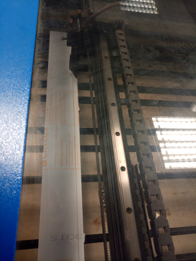
Testing the machine
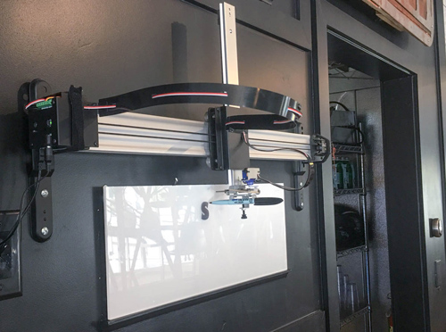
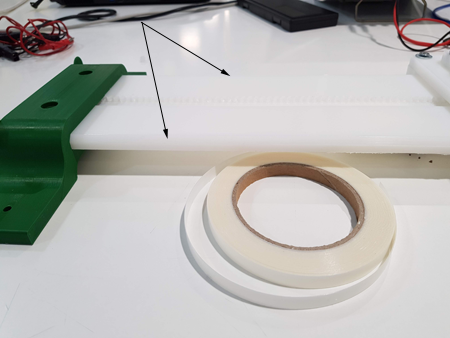
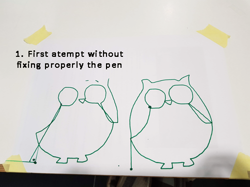
To be able to perform some tests with out machine we drill a hole at the end of the y axis and we inserted a pen. Then we sent comands through the Serial monitor moving the axis together to different positions: for example: G91 G0 X50 Y-30.
We put some UHMW tape on the border of the axis to reduce the friction between the different pieces. Like this the movement became smoother. By adding this we also had to release a bit the screws that were putting the pieces together as the size of the axis had increased.
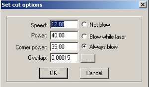
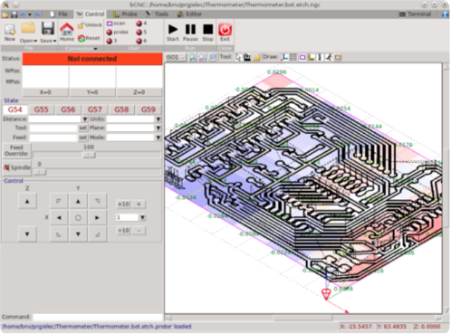
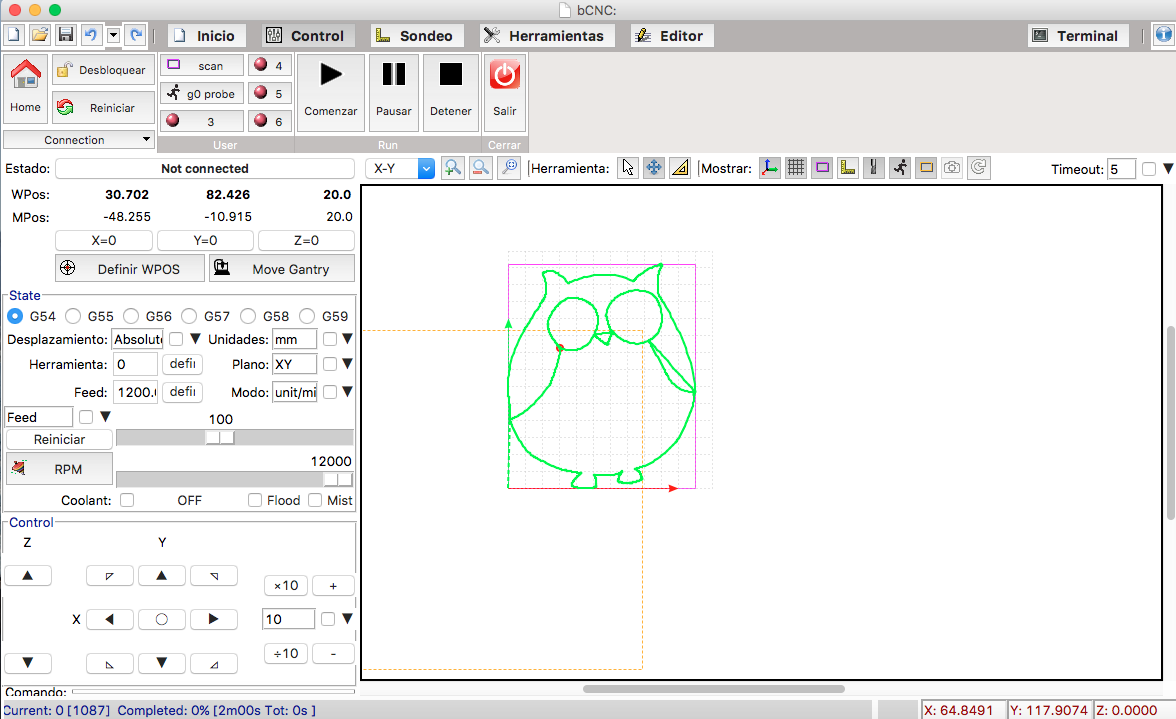
bCNC
Once the axis were working properly we downloaded a GUI that allowed us to transform a .dxf image into Gcode comands. This comands will be sent to GRBL board and the motors will move our axis to the desired positions. In the GRBL wiki we had some GUIs recomendations. We decided to download the first one that appears in the page: bCNC.
Using bCNC
The .zip file that contains bCNC can be found in its Github page. We donwloaded it and then we followed the wiki instructions to install it in my Mac OSX computer. Its important to know that this GUI works with Version2 of python. In my case I had to unstill version3 and install the second one for it to work.
Once we manage to install it we run the program by going to the file directory and typing./bCNC.
The GUI opened and we first selecting the port that we were using to connect the Arduino and then we clicked on Open file to load a sample design.
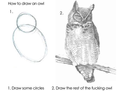
Following the advice for drawing of this week we decided to start drawing the shape of an owl...
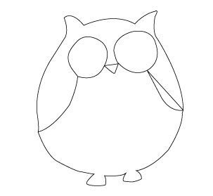
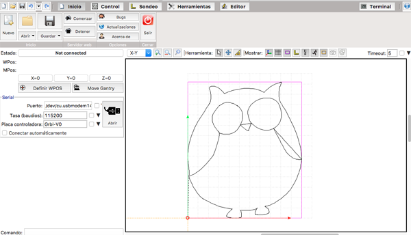
We did a sketch of its shape in Illustrator and we exported it as a .dxf. The steps that we followed in bCNC were:
- We connected our machine and we opened the port connection in the Home window.
- We placed the pen that we have placed on the Y axis in the starting point and then we defined this point as the origin by clicking on the
X=0, Y=0 and Z=0. In our case we are not using Z but just in case. - The buttons than enables us to move the machine are located at the bottom of the window, being the center one the one that allows us to go back to the home position.
- Once we have establish our settings we opened the file that we wanted to draw in .dxf format and we went to the Editor window.
- There we moved the design to the left bottom corner and we checked what was the path that machine was going to do to draw it.
- When everything was ready we went to the control window and we started the process!
Future development opportunities for this project:
Next steps include designing the end effector that will hold the pen and will allow us to draw with more accuracy.