Assignment
- Test the design rules for your printer
- Design and 3D print and object
- 3D scan an object and print it
Personal objectives
- - Know about the design rules for 3D printing and the influence of materials and printers in the results
- - Learn the 3D scan technique and the methods to fix the scans
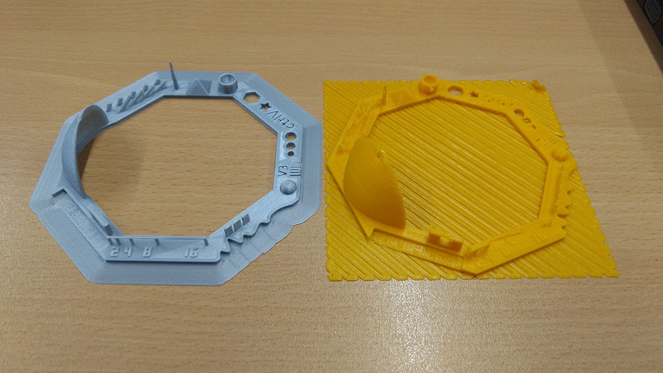
3D Printer test
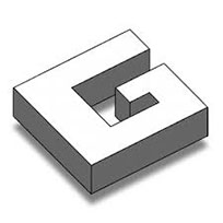
For this part of the assignment I Just test a model for testing available in thingiverse: Ctrl V Test in the two printers available at Anáhuac Querétaro: A ultimaker 2+ Extended an a XYZ DaVinci 1.0. This test include several features as Z-Height check, Warp Check, Spike, Hole in Wall, overhang steps, sharp edges, minimal distance, bridge print, sphere, etc. The result from each printer are showed in the Figure 2 and some of the features are summarized in the table after that.
| Test | Ultimaker 2+ | XYZ DaVinci 1.0 |
|---|---|---|
| Nut, Size M4 | ✔ | ✖ |
| Not well define edges at the bottom | ||
| Wave (Rounded print) | ✔ | ✔ |
| Star (Sharp Edges) | ✔ | ✖ |
| Not sharp edges, more rounded than sharp | ||
| Name (complex shapes) | ✔ | ✖ |
| Not quite defined | ||
| Holes (3, 4 and 5 mm) | ✔ | ✖ |
| rests of materials Through the hole | ||
| Bridge print (2, 4, 8 and 16 mm) | ✔ | ✖ |
| The largest bridge show some curling below | The small distances was fine at first but break very easy | |
| Hole in Wall | ✔ | ✔ |
| The hole is ok but change to an ellipse | ||
| Quarte shpere | ✔ | ✔ |
| The sphere is ok, but with some gaps at the top |
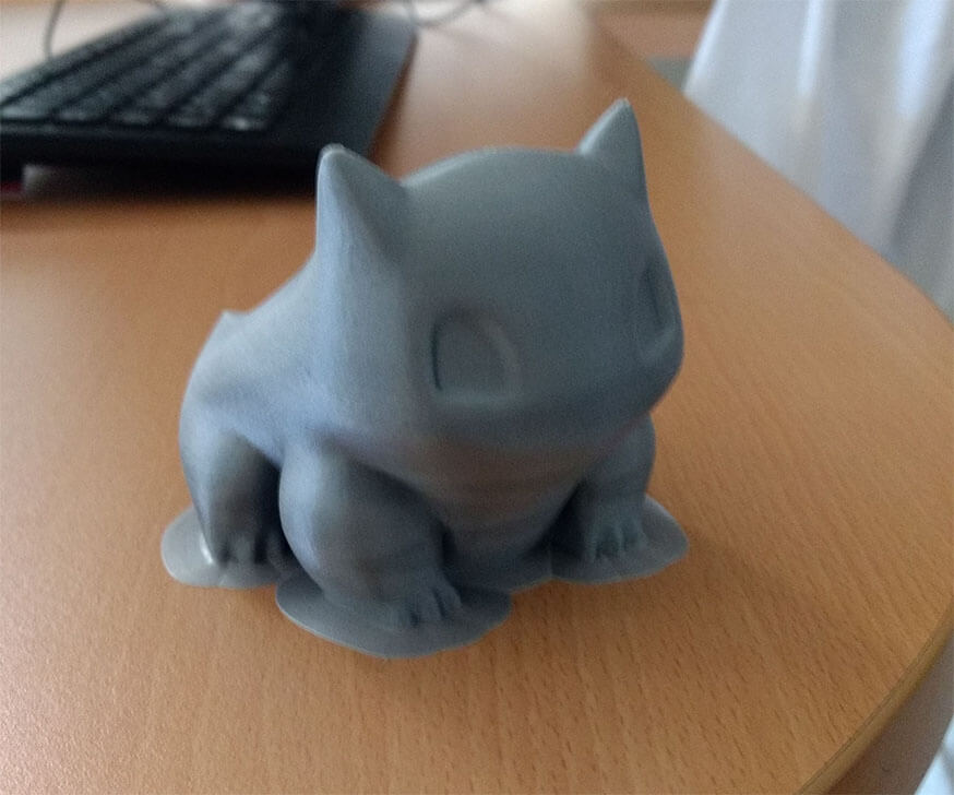
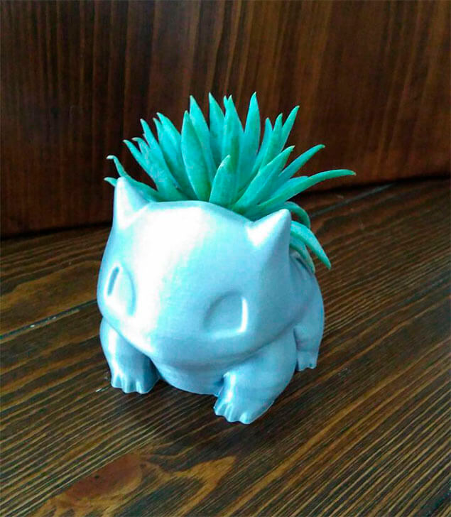
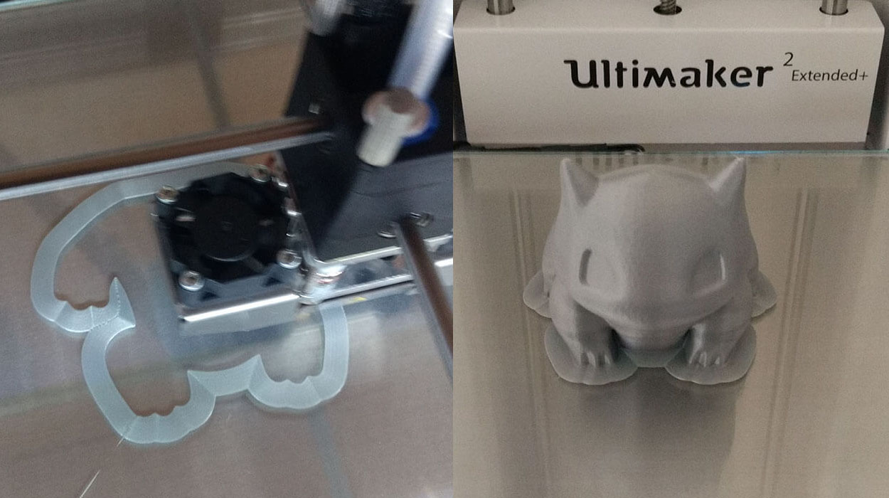
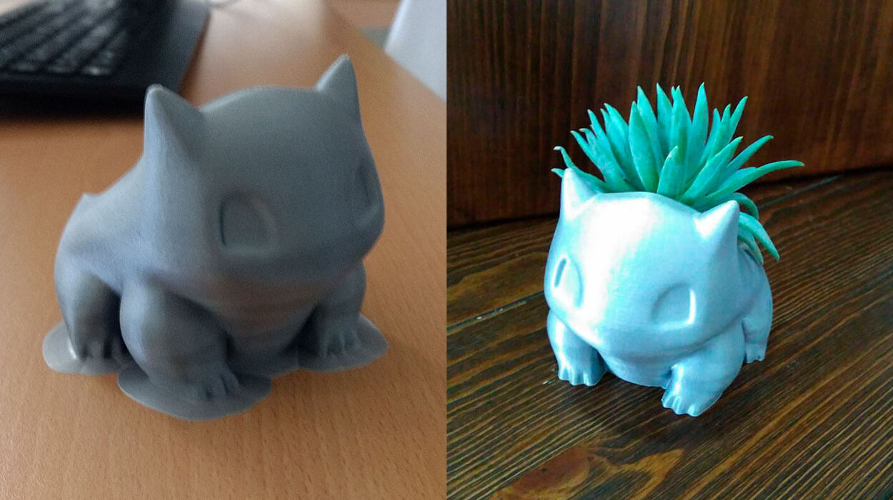
After the test, I tried another model from thingiverse (Bulbasaur Planter High Res ),
just to test an high resolution model with the best resolution in the Ultimaker 2+. The result was a beautiful planter with a very
smooth surface and very good finishing (Figure 3 and 4)
Create and print a model
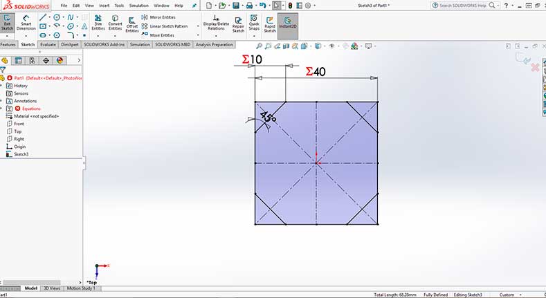
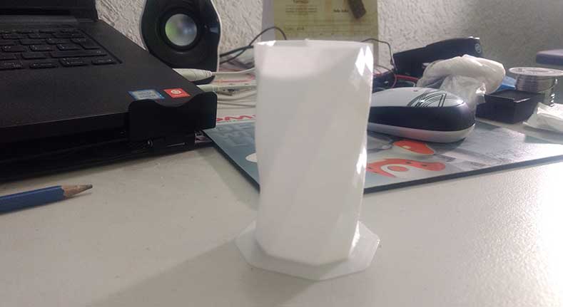
I Also create a simple model in Solidworks to test the Vase or spiral mode.
This mode build the model in one string by moving the extruder in an outline or perimeter shell without any retracts.
So the extruder will move slowly in the Z-directions as it prints. The vase mode has two great advantages: The printing time
and the amount of material use will be reduced a big deal.
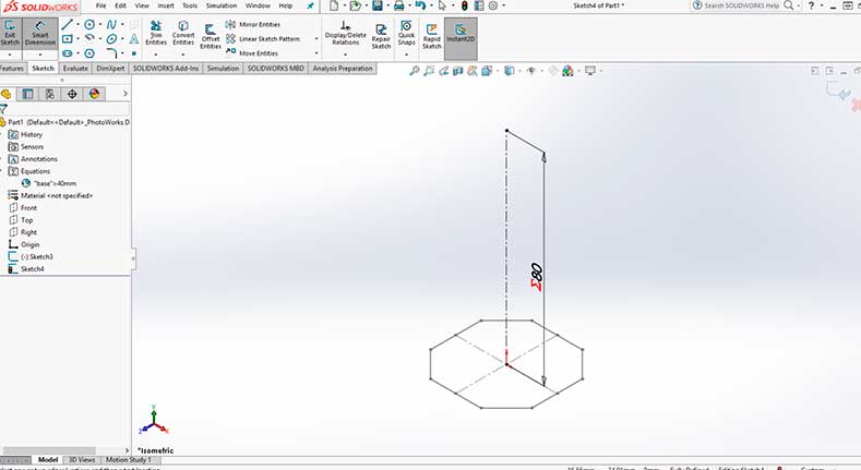
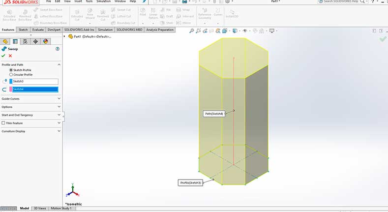
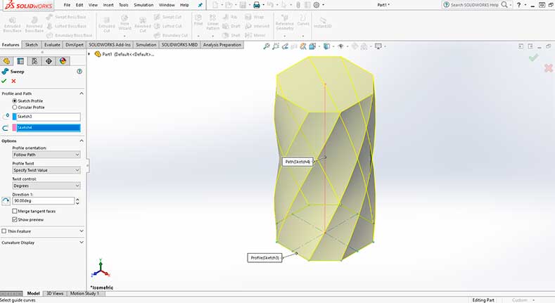
For the creation of the model I used the sweep boss/base in solidworks, the construction can be see in Figures 5 through 8.
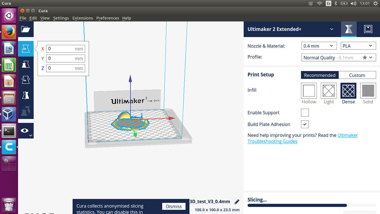
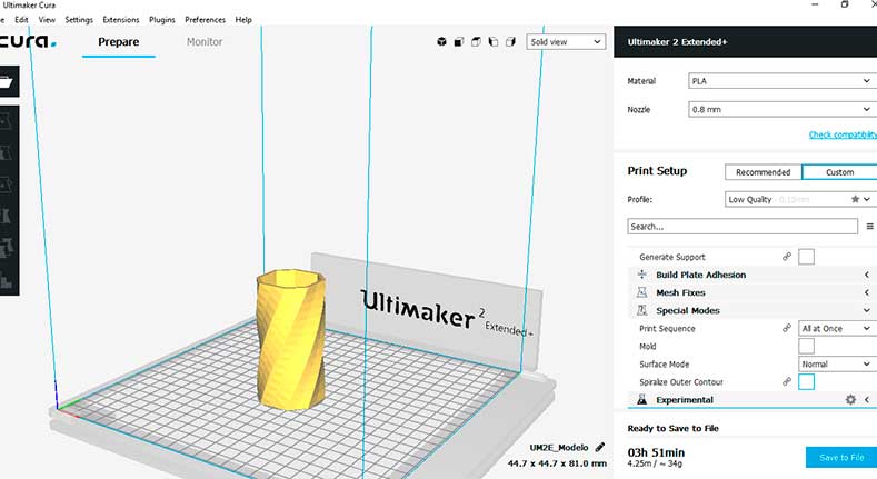
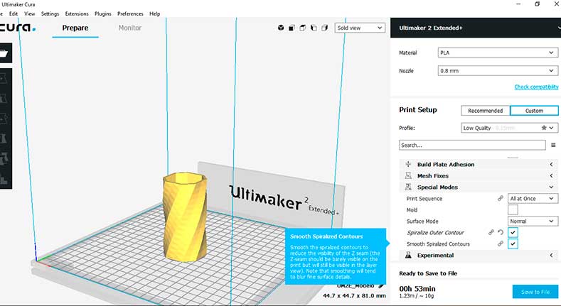
Once the model is complete and save as .STL file must be open in Cura . For print it in vase mode is necessary go to custom setup and look for special modes and check the Spiralize Outer Contour and in my case I also check he smooth Spiralized contours (Figure 10). As mentioned before the time an amount of material is reduced by a fourth. (Figure 9 and 10). The model was printed in PLA with a 0.8 mm nozzle.
3D Scanning
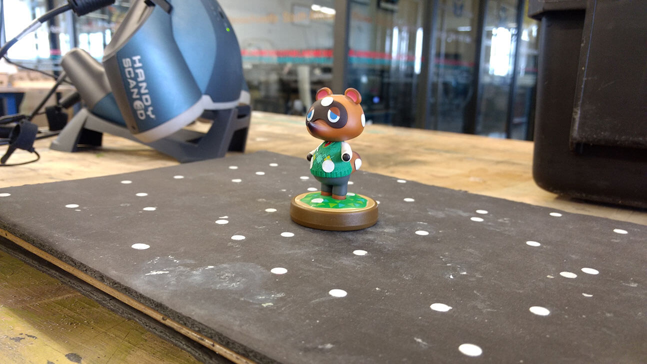
For the 3D scanning I wanted to use a small figure to be able to print it in real scale after the scanning. That´s why I used an Tom Nook amiibo (a small nintendo’s collectible from animal crossing game, figure 5). The scanner used was a Creaform – Handyscan 3D, which works with the VX Elements software.
The procedure to make the 3D scanning is necessary to place positioning targets in the figure and, if possible, in a nonreflecting surface.
This positioning targets (made of reflective tape) are necessary in order to give the scan a location of the object. The position targets are important due to the manual operation of the
scan and the fact that is not always scanning from the same position.
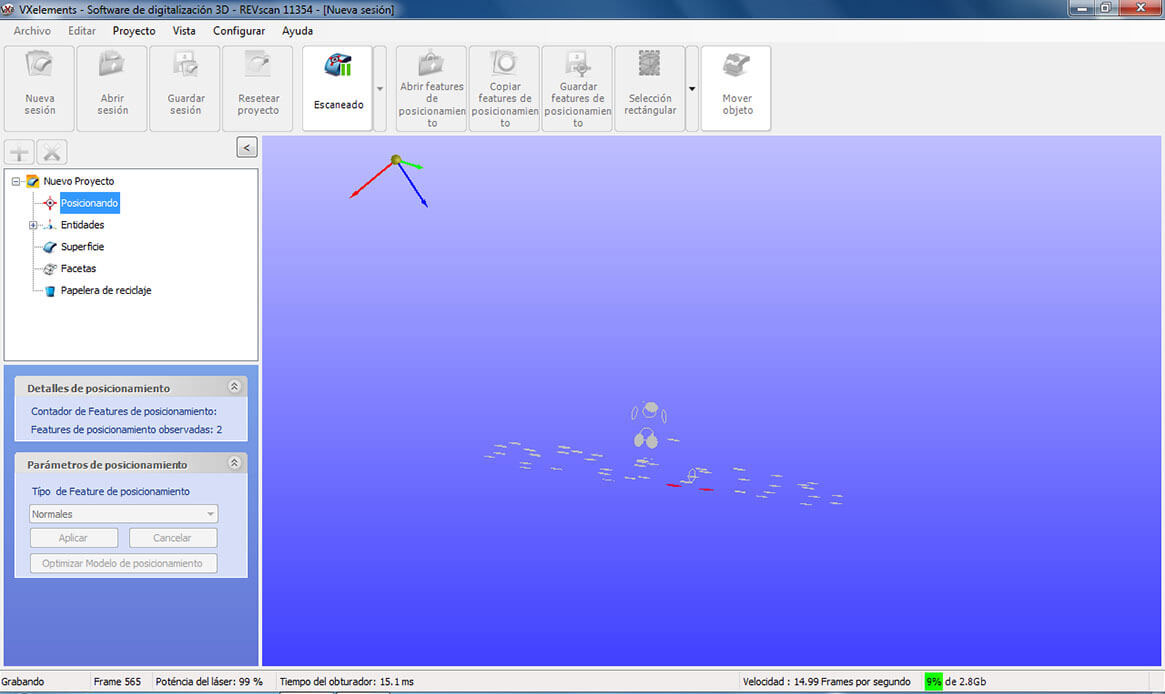
After the position targets are located, the scan needs to be connected to the PC and the VX Elements software ready for scanning. The Handyscan has a trigger to activate the laser
and the reflection received in the scanner sensors start to create the figure (Figures 6, 7 and 8)
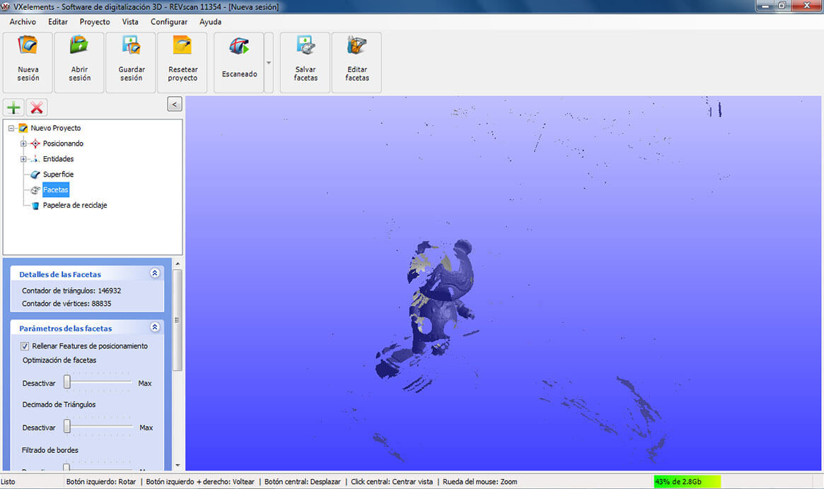
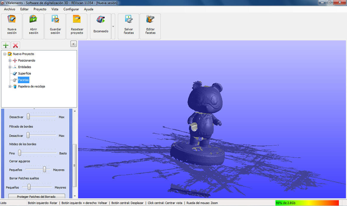
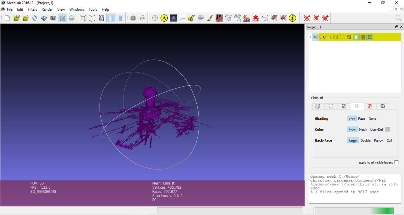
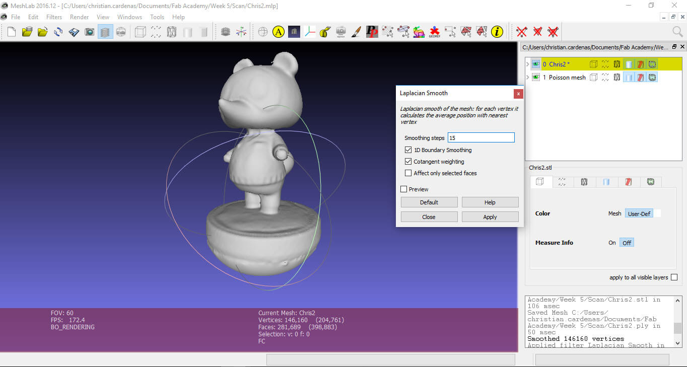
Once the scan is complete is necessary to clean and fix the result. As is seen in figure 8, the model is not quite complete: the white zones are holes in the model (positions targets and difficult points to reach with the laser). To fix the model I used the open source Meshlab software (Figure 9). In the figure 10 the holes in the model are more visible.
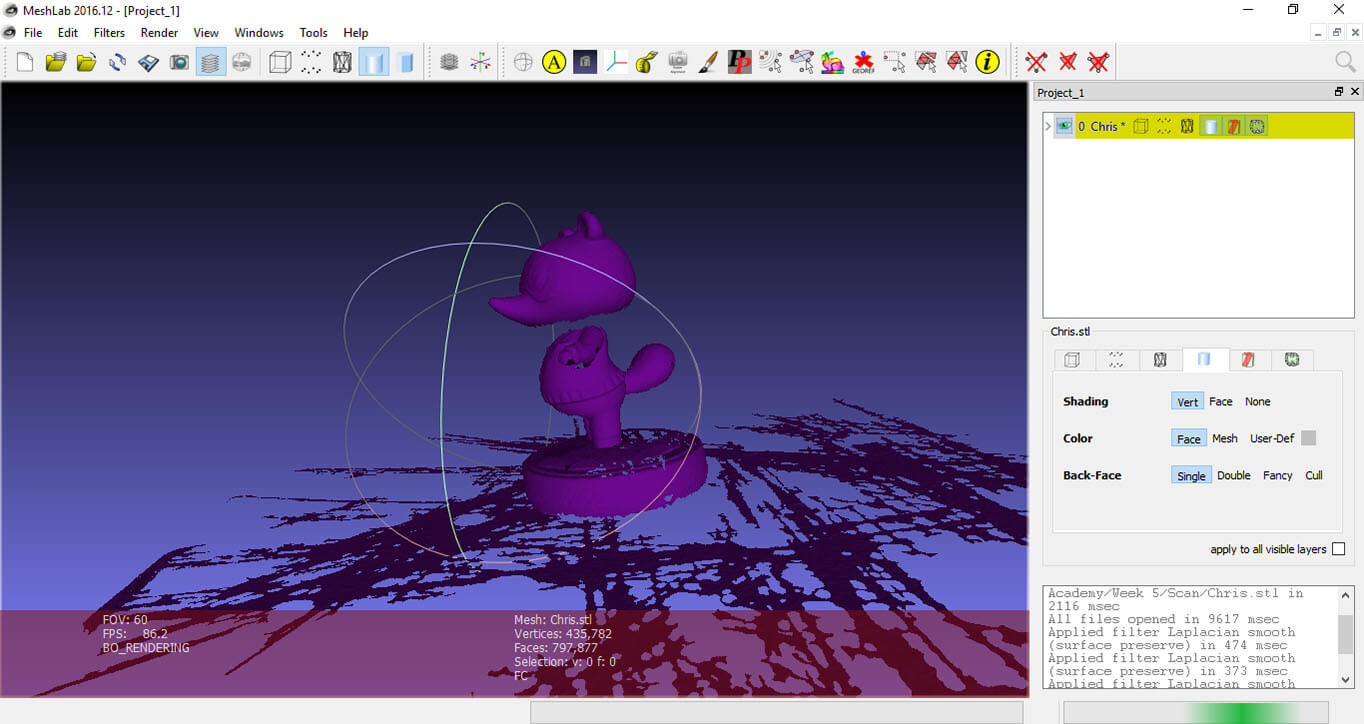
The first step is to clean the model as much as possible, this is as simple as select and delete. After the model is clean I performed a Poisson surface reconstruction with the parameters show in figure 11. This surface reconstruction fills the voids in the model predicting the shape of the surface that should be in the holes. After the surface reconstruction is a good idea to smooth it, I made this using a Laplacian smooth with the parameters show in figure 12.
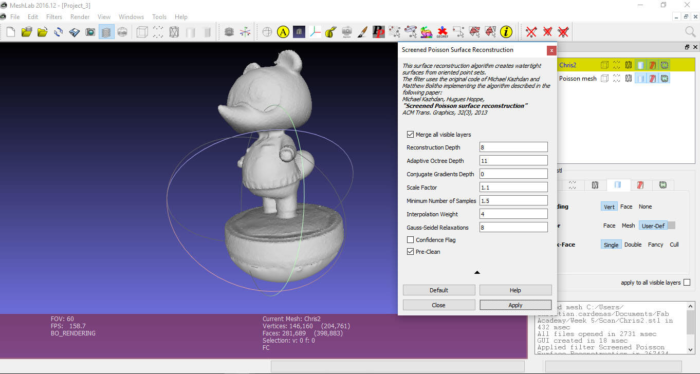
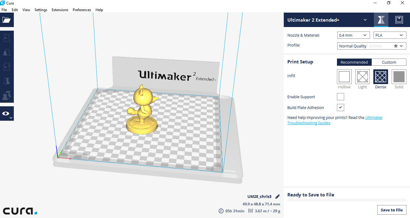
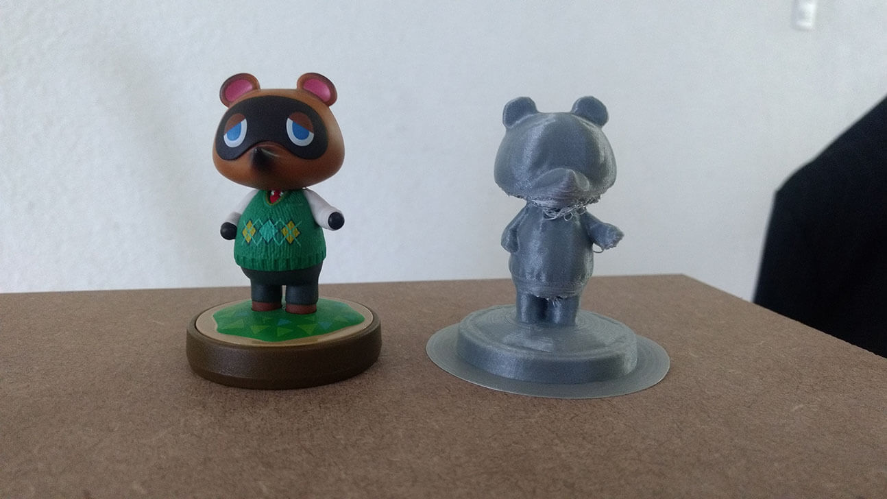
As is can be see the surface reconstruction (figure 11) a demi sphere was created below the model, this is a problem with a very simple solution: in the cura software (or any other software to control the 3D printer o generate the .gcode) move the model until the non-flat part is below the workspace of the 3D printer. The 3D printing of the scanned model is shown in figure 13, besides some curling of the filament in some areas (probably lack of supports) the result was quite good, and now Tom Nook has a twin (or something like that).
Files
In this section the files generated during the development of the assignment will be available to download. The files of the models
of the 3D printer tests are available in thingiverse, the links were provided as they were mentioned.

|

|
|
|

|
|
| Scan_result.stl | Meshlab_project.zip | Fix_model.stl | Tom_Nook_model.gcode | Vase.SLDPRT | Vase.gcode |