Group Assignment for the Week 5, the process of cutting the ‘linetest’
Group members
Fabmodules.org for creating.rml -files
For starting the group work we downloaded the files of linetest .png files of linetest traces and linetest interior. We did fabmodules.org to make the files for Roland SRM-20 milling machine as follows:
- Set ‘input format’ to be ‘image (.png)’ and navigate the png image “linetest.png”
- Set ‘output format’ to be ‘Roland mill (.rml)’
- Set ‘process’ to be ‘PCB traces (1/64)’
Then, set ‘output’ machine to ‘SRM-20’
- Change the values of x0, y= and xz0 (mm) to 0, since on our machine we don’t need this offset, since we will define the origin manually.
- Define the cut depth (mm) to be 0.10 – 0.14 (mm)
- Further, check the ‘tool diameter’ to be 0,4 (mm), and that ‘offset overlap’ is 50 (%).
Then, press ‘calculate’ to see the lines the milling machine will draw, and furthermore ‘save’ the .rml -file.
For linetest.interior .png, do the same, but
- Set ‘process’ to be ‘PCB outline (1/32)’.
Then, check that the image size matches with the size of previous one.
- Again, set ‘output’ machine to ‘SRM-20’ and change the values of x0, y= and xz0 (mm) to 0.
- Lastly, define ‘tool diameter’ to be 1 (mm).
Press ‘calculate’, and ‘save’ the .rml -file.
Preparing Milling Machine
Open the program ‘VPanel for SRM-20’. Open the door of the machine and remove the ground plate by opening the four screws. Take a plotting board (PCB). In Fab Lab Oulu we have fr-1 which has light sensitive coating and take the tape off above it. Turn the board upside-down to see the background and put tape stripes carefully above it. This is a crucial part and they cannot overlap at all since otherwise the board will be bended. Cut the extra tape off from the sides and clean the board. Check the surface of the plate, which has to be absolutely straight and level. Put the plate back inside the milling machine right way up and tighten the four screws tighten.
In VPanel, set the origin of Z-, X- and Y-axes. Move the head to the ‘View’ position so, it moves to the center and it is easier to install a milling bit. Open the small screw, put the xxx-size milling bit in all the way up to colored neck, and slightly tighten the small screw in shank by allen key to fix it. Then, define the origin of Z-, X- and Y-axes, where X- moves the table, and and Y- and Z-axes moves the head. Move the axes manually by the VPanel arrows with appropriate ‘Cursor Step’.
- ‘Continue’ moves as long as you push it, by which you will move near to the aimed origin, then x100 will do smaller steps to get closer and x10 getting nearby the surface.
When X- and Y-axes are close enough, reset them to be a new origin. Move the Z-head carefully near to the surface. Then, hold the milling bit, loose the screw and move the bit to the surface, and then tighten it again. Now, reset the Z-axis to be zero and then move Z-axis just a little bit up (around 5steps with the x100) so, don’t leave it to the surface. Now the machine preparation is done.
Milling the PCB
In VPanel, select ’Cut’. ’Delete All’ from the Output file list, and ‘Add’ new one by navigating the first .rml file of traces and opening it. When you press ‘Output’, everything else has to be done, since it will start cutting straight through.
After the first file was cut, without touching the origin, we opened the door of the machine, cleaned it by a vacuum cleaner and, removed the first milling bit. Now we changed the milling bit to be the 1 mm bit, and then, for the interior -file, we repeated the steps done for the first .rml file in order to cut the outline and be able to remove the cut board from the whole sheet. However, we faced a problem with the bottom line which wasn’t cut. Since the origin was still there, we decided to cut it again. This time we paid better attention to check the print preview and noticed, that the bottom line was marked as red meaning to be uncut. At first, we thought that the line could be too thin and wondered to make in thicker by editing the picture. Then we came up to make some changes to the cutting settings and changed the tool diameter to be 0,3 mm (instead of 1 mm) and this way it seemed that the line will e cut, which was the result after cutting as well.
- --- More different trials before finding the right setting...
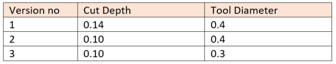
We repeated the process three times, in order to see the results of three different settings:
We also experienced the differences between a flat and a v-shaped milling bit…
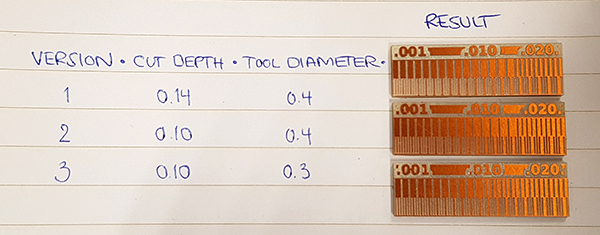
- For Version 1, with a cut depth of 0.14mm and tool diameter of 0.4mm the minimum insulation gap achieved was 0.16mm and the trace width was 0.001
- For Version 2, with a cut depth of 0.1mm and tool diameter of 0.4mm the minimum insulation gap achieved was 0.16mm and the trace width was 0.001
- For Version 3, with a cut depth of 0.1mm and tool diameter of 0.3mm the minimum insulation gap achieved was 0.12mm and the trace width was 0.001