Assignment 17: Wildcard week
Assignment:
Individual assignment:
- Design and produce something with a digital fabrication process
(incorporating computer-aided design and manufacturing) not covered in another assignment, documenting the requirements that your
assignment meets, and including everything necessary to reproduce it. Possibilities include (but are not limited to) composites, textiles,
biotechnology, robotics, and cooking.
My goals for the wildcard week
- Make a vacuum formed object related to my final project.
- Do 3D model of the final project and pick a part for the vacuum forming.
- Do CAM for the CNC machine and produce a mold for the vacuum former.
Mold design
I wanted to do this week something that gets me forward in my final project, so at first I was thinking about making a vessel for my hydroponic nutrient solution using composites, but Jani told me that they have not yet managed to make a composite structure that holds water. Then he suggested that, I could use vacuum forming machine to do it, but it was too small to make that kind of vessel. The maximum dimension, for the height was 140 mm. The biggest frame is 430x450 mm. Therefore, the vessel would have been quite small and I decided to make two vessels for the pH meter storage solution, which I need for the final project as well. At first, I studied the mold making and found an excellent guide from Formtech International Ltd. Since the top surface of the moulding has the better finished surface, I started to work on a male mold, so it would look nicer to person watching the part. It was also suggested by laboratory master from the architectural department, who operates the machine. There was no previous experience in our Fab lab regarding vacuum forming and there was no suggestions on the mold.
I started to make a design of the whole structure in Autodesk Inventor 2018, to be able to evaluate the dimensions of the pH meter storage solution vessel. At first, I created the acrylic box, which acts as a vessel for the hydroponic nutrient solution. It is simply a box with dimensions 500x300x400 mm (60 liters) and I used shell function to make 3 mm thick walls.
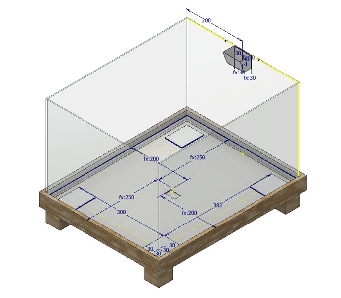
There is no lid at this point, because everything else needs to be implemented before it can be designed. Then I created a holding structure, which is to be made of osb. It surrounds the bottom part of the vessel and has places for the wight measuring load sensors and its board.
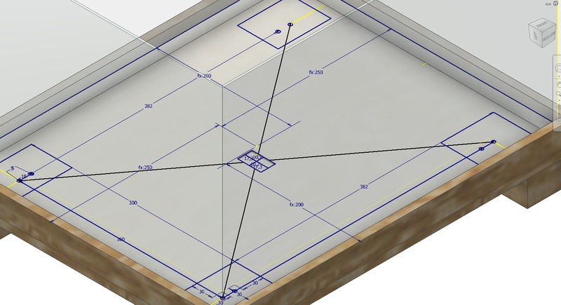
On top of the load sensors is another osb board, which has metallic plates to prevent the load sensors from burrowing in the osb and the whole structure can rest on the load sensors and it can be weighted. It was hard to think how I could measure the weight of the solution, but when I started to make the 3D design it came to me and I think this is going to work. On the side of the hydroponic nutrient solution vessel is a place for the pH meter storage solution vessels.
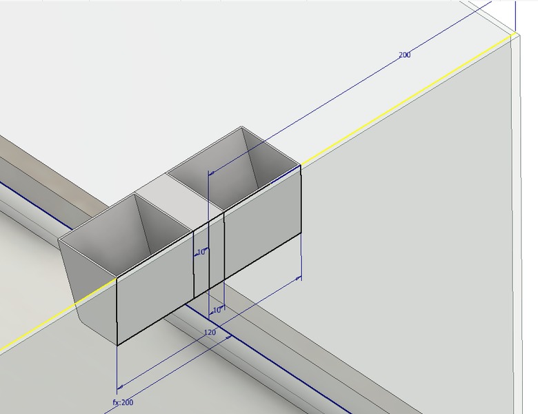
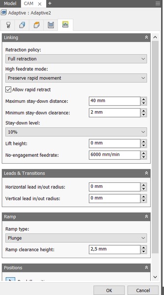
I made the pH meter storage solution vessel into its own part and started to work on the CAM. I decided to use adaptive 3D milling method, because it makes the roughing and finishing at the same time. The CAM is explained in the Computer controlled machining week and I only present the adaptive method. Setup is done similarly and the origin is set to upper left corner of the stock and all the offsets are put to 0 mm. I used the 8 mm ball nosed tool. The clearances are put in a similar way to 2D milling. Maximum stepdown was 5 mm and fine stepdown was 1 mm.
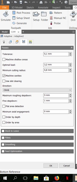
I put leads and transitions to 0 mm and selected the ramp type to plunge.
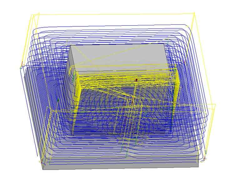
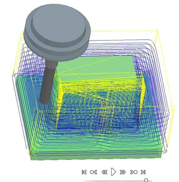
I simulated the cut and everything seemed to be ok and the machining time estimate was about 11 minutes.
Mold preparation
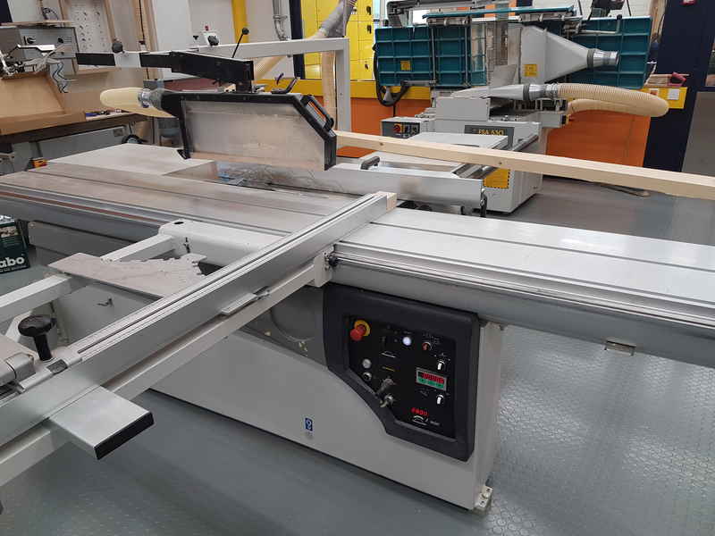
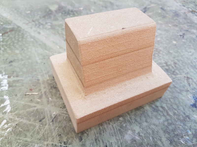
I used MDF board to make a mold. I used circular saw to cut the board in 8 cm width pieces. Then I glued four of these together to make 8 cm high stock material. The length was about 30 cm.
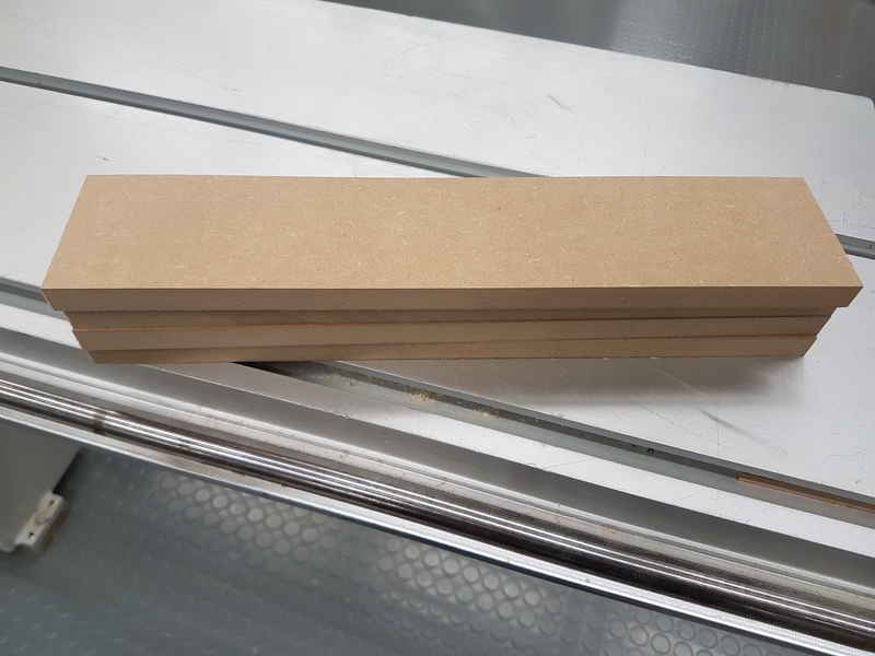
The glue was drying over the weekend and the mold material was ready for milling on monday.
Because the material was 80 mm thick and our 8 mm ball nosed tool is only 50 mm long, I knew that the mold had to be at maximum 50 mm in height. I made my pH meter storage solution vessel 40 mm high and I knew that I have to use bandsaw to remove the mold from the stock material.
CNC milling
The milling part is similar to Computer controlled machining week and I will only go over the details related to this particular job. I switched the 8 mm ball nosed tool to machine. To get the mold material screwed on the sacrificial board, I screwed an osb board in the bottom of the material and then screwed the osb board in the sacrificial layer. Then I zeroed the CNC machine on the stock material and simulated the job. It seemed to work in the simulation and I started to cut.
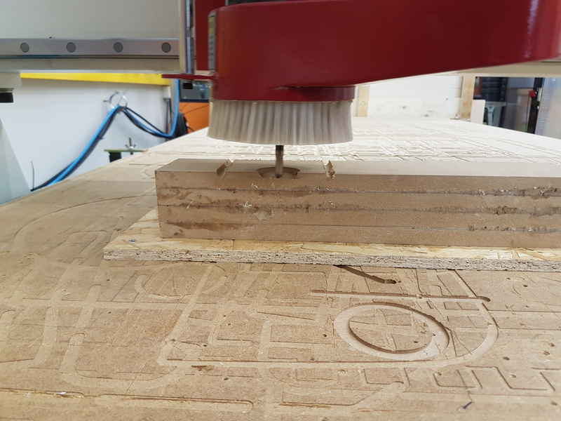
I manually stopped the machining when the final layer was finished. The code still included the milling of the corners, but I couldn't do that with the tool we had available.
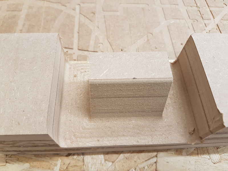
I removed the stock with mold still attached to it and used bandsaw to remove the mold. It worked nicely and I got the mold ready for the vacuum former.
Vacuum forming
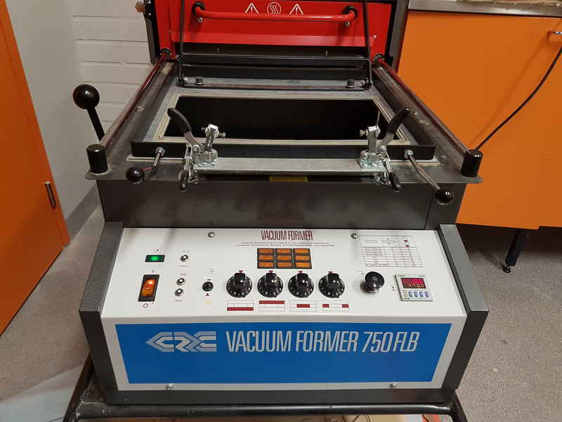
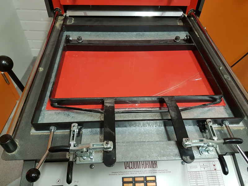
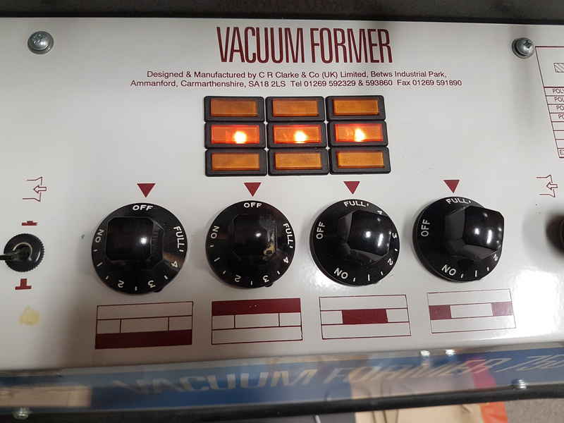
Our vacuum former is Vacuum former 750 FLB.
The vacuum forming requires a board below the actual mold to make the vacuum in the desired area and I used circular saw to make it.
After that I drilled a hole through the board for the vacuum (8 mm hole) and through the mold as well (4 mm hole).
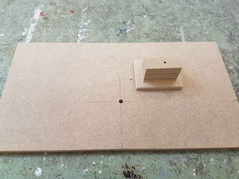
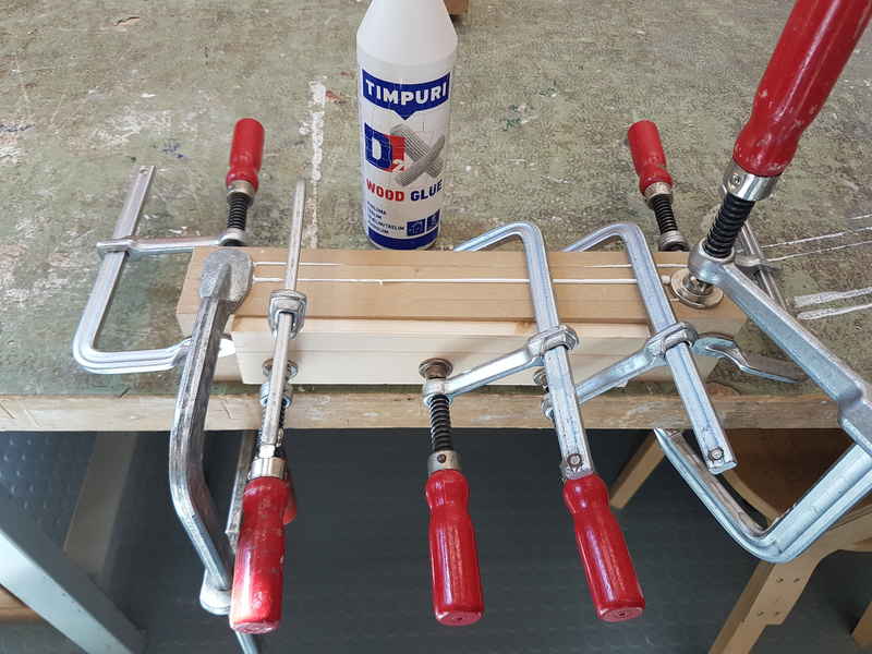
Then I glued them together using wood glue and I aimed them in a way that the holes were perfectly aligned. I used 4 mm drilling tool to align the parts by putting it through the holes. I removed the drilling tool and used a clamp to keep them from moving and adding pressure for the glue to dry.
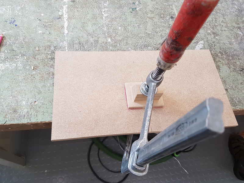
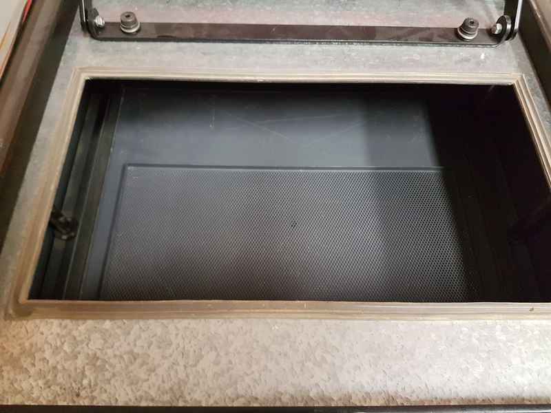
I let the glue to dry about 30 minutes and the mold was ready for the vacuum former. I placed the mold in the vacuum former with the vacuum hole aligned with the mold.
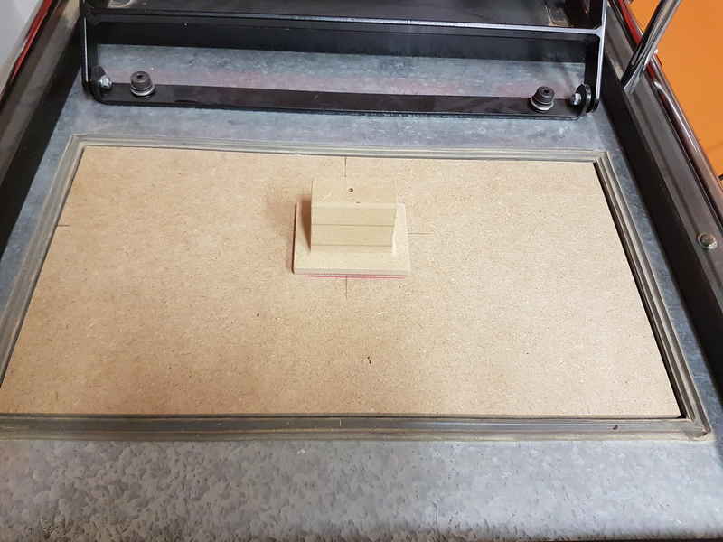
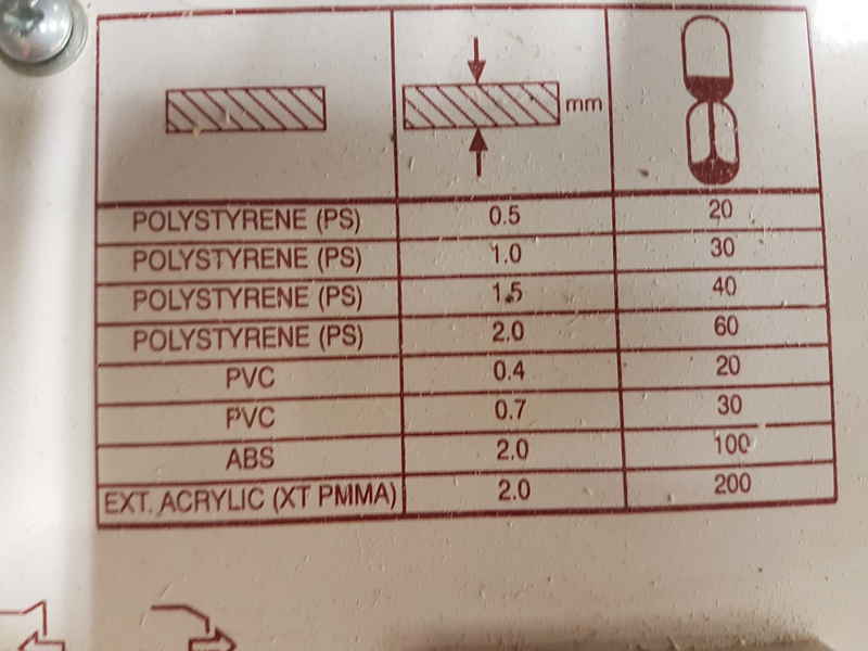
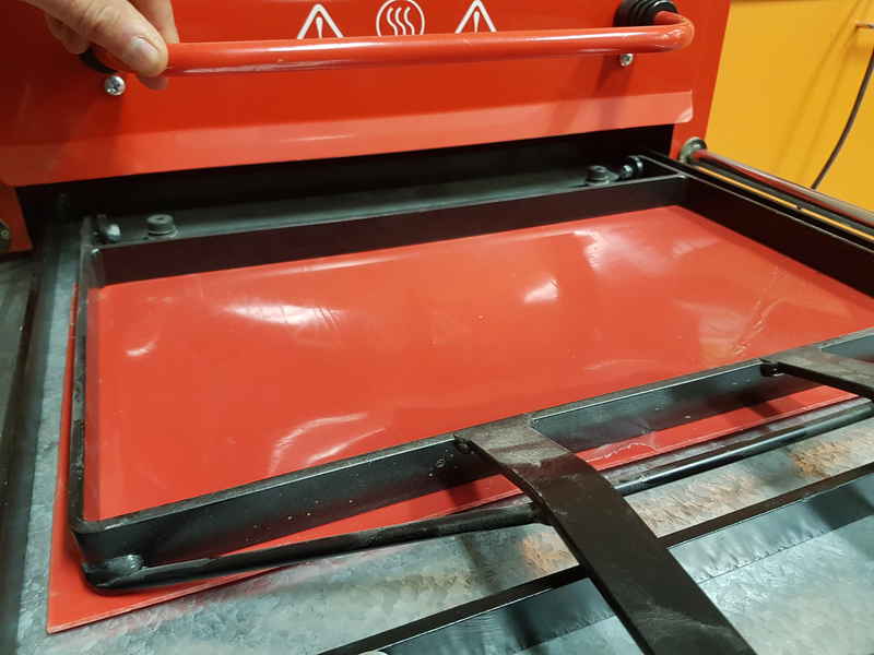
I lowered the mold in the machine and placed a 2 mm polystyrene (PS) sheet in the frame for heating.
Heating times are related to material. With 2 mm PS the heating time is 60 minutes, but according to laboratory master, you can do the vacuum forming when material is clearly softened and wait a few minutes after that to make sure.
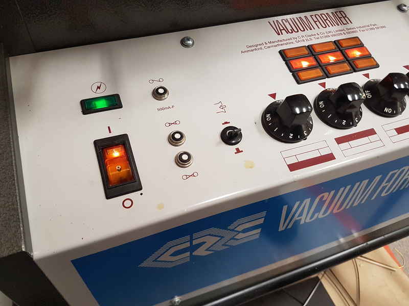
I turned the heating to full in the middle layer using two switches on the right.
It took about 15 minutes for the PS to clearly be soft and I started to do the vacuum forming.
With lever on the left side of the machine, I pulled the mold against the PS and I activated the vacuum at the same time with my right hand.
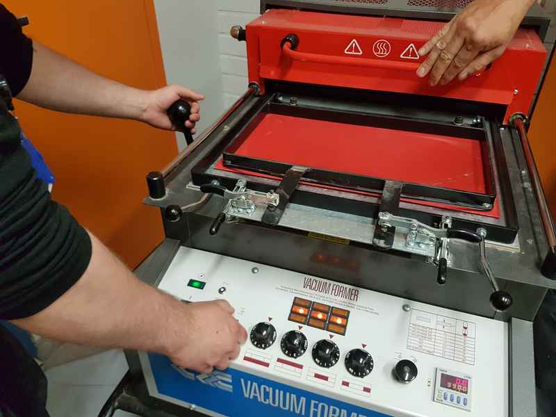
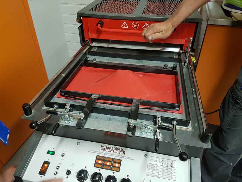
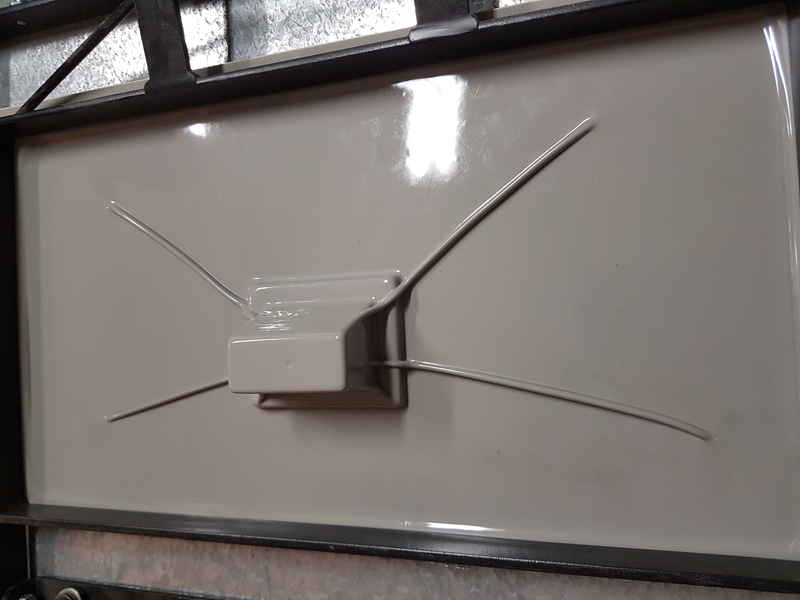
When the mold is pressed against the PS and vacuum is formed, the PS quickly starts to take the mold form. The following images are only a few seconds apart from each other.
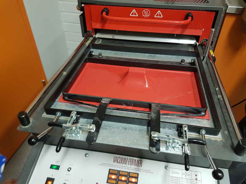
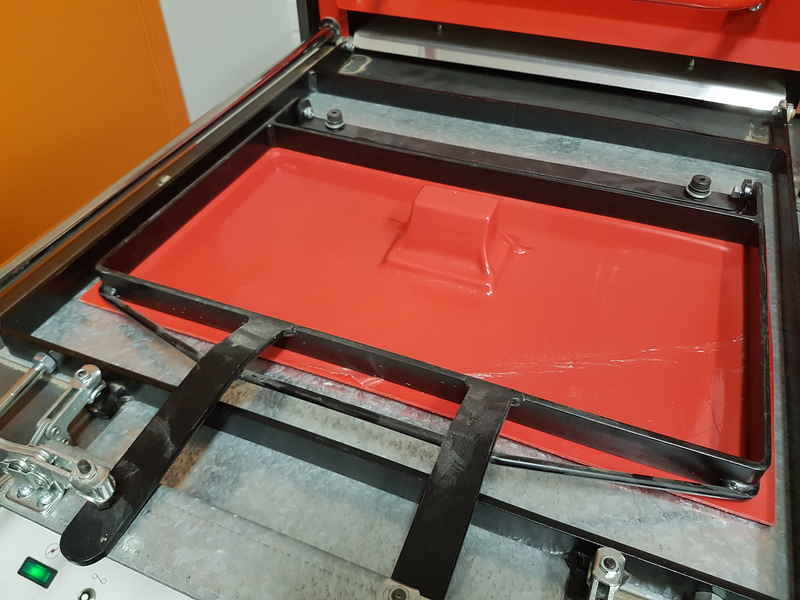
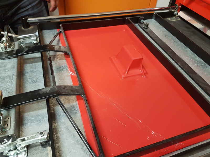
The heating is turned off when the vacuum forming is started and the plastic is let to cool down on the mold for it to reach its final form. Mold with PS can be removed by hand after a few minutes of cooling.
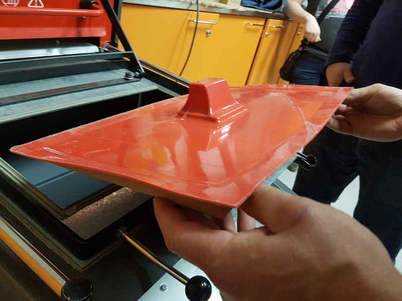
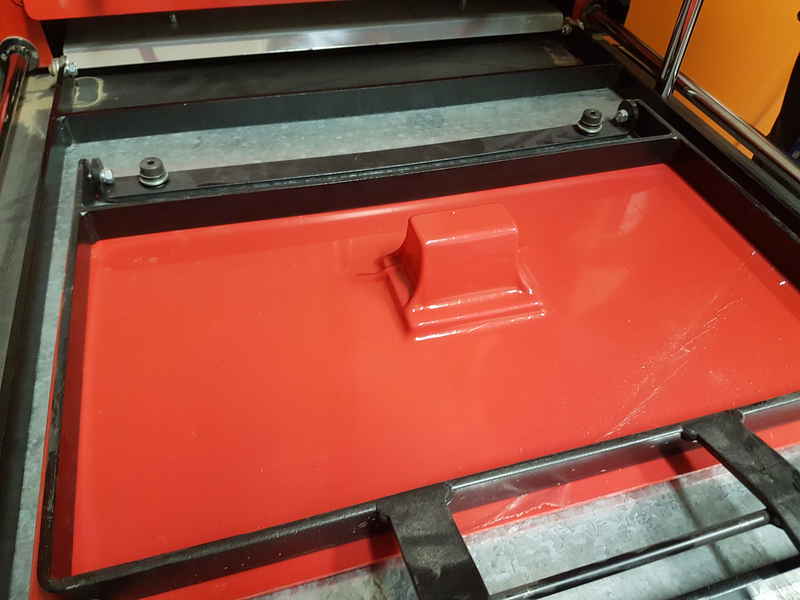
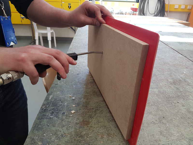
The mold removal is easilly done with a short burst of pressurized air. It pops right off and you can lift the PS off the mold.
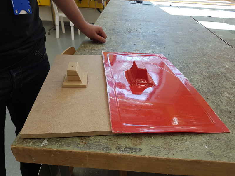
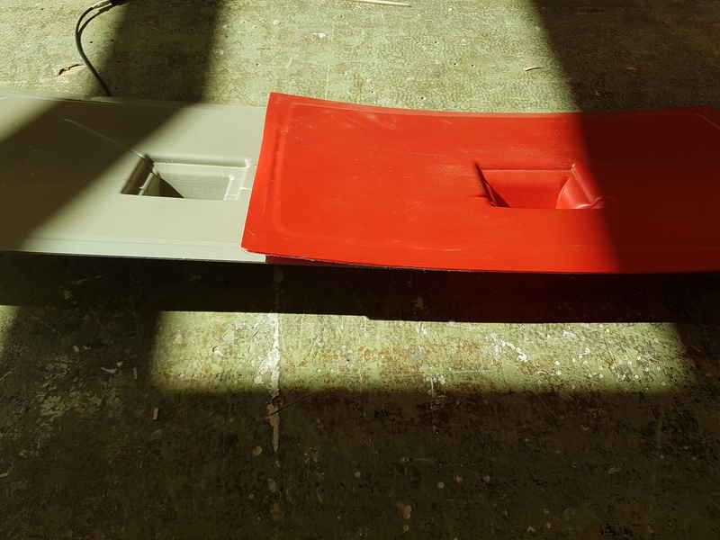
I made another vacuum forming to make another vessel. The plastic was different color, but it was the same material otherwise. I let it to heat longer this time and it can be seen that the PS took the molds form better. The problem was that the wrinkles in the PS were also sharper.
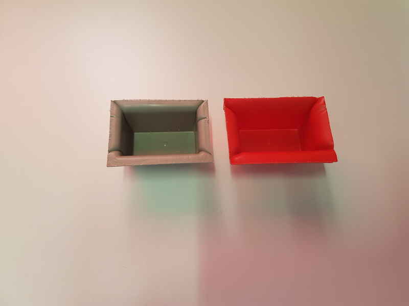
I used bandsaw to remove the vessels from the extra PS sheet. The final product is not perfect and I have to consider, whether I'm going to use these in my final project or if I will cut them from acrylic with laser cutter.
Reflection on this weeks assignment
This weeks assignment was interesting and I got to work with vacuum forming machine, which no one had used before in our lab. It was fun process, yet a bit stressfull with the mold making, because I was not sure if it is going to actually work. It was also almost impossible to find PS sheet in Finland without ordering it from somewhere and the minimum size was 2 m2. Luckily, there was some small pieces left in the architecture lab and I was allowed to use those. The final product was not very good quality and I think that using a female mold, would have been a good idea for this kind of product. Unfortunately, I didn't have time to do that (or PS sheet). I think it would be good to have for example 100 mm long milling tools for wood CNC in the lab to make mold making easier. Now the mold size is very limited and it is not very relevant method in real world applications. Of course, you can do this by layering several pieces and gluing them together, but it has limitations in the mold surface quality and accuracy and it is more time consuming. Bas suggested that I could have made extra air holes in the bottom corners of the mold. It was also instructed in the guide I read, but laboratory master said to me that it isn't needed. Clearly, I should trust professional literature a little more.
The files used in the assignment are shared below:
Week17Files.zip All the 3D modeling files, STL files and NC file that I created during wildcard week.