Assignment 4: Computer-Controlled Cutting
Assignment:
group assignment: characterize your lasercutter, making test part(s)
that vary cutting settings and dimensions
individual assignment: cut something on the vinylcutter
design, lasercut, and document a parametric press-fit construction kit, accounting for the lasercutter kerf, which can be assembled in multiple ways
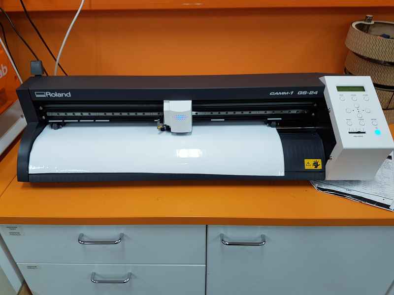
We started to practice using vinyl cutter with our whole group in the morning of 8.2.2018. I got the honors to be the test user, because I had no previous experince with the machine. Our vinyl cutter is Roland CAMM-1 GS-24, I inserted the roll of vinyl inside the vinyl cutter and locked it in place.
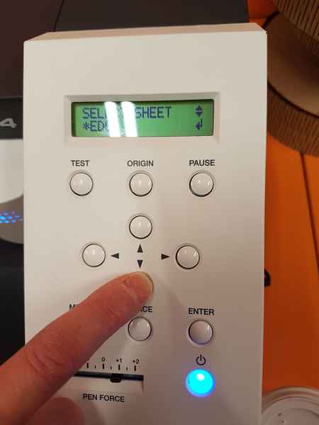
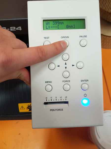
You can set the origin point for the cutting or use the side of the sheet. The cutter is moved with arrows and you can select the point of origin by holding down the button for a few seconds. You can see the width of the vinyl in the LCD screen W: 399mm. This has to be set as the width of your document in the Inkscape, if you are using it. In Inkscape select File > Document Properties > Custom size width: 399 mm. The height of the document should be more than its width or the vinyl cutter automatically rotates the cut 90 degrees.
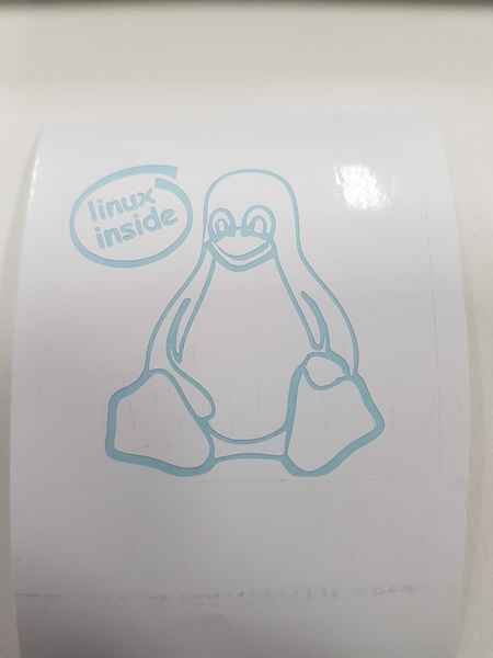
In the cutting process, you can see the cutter move quickly on the vinyl sheet. 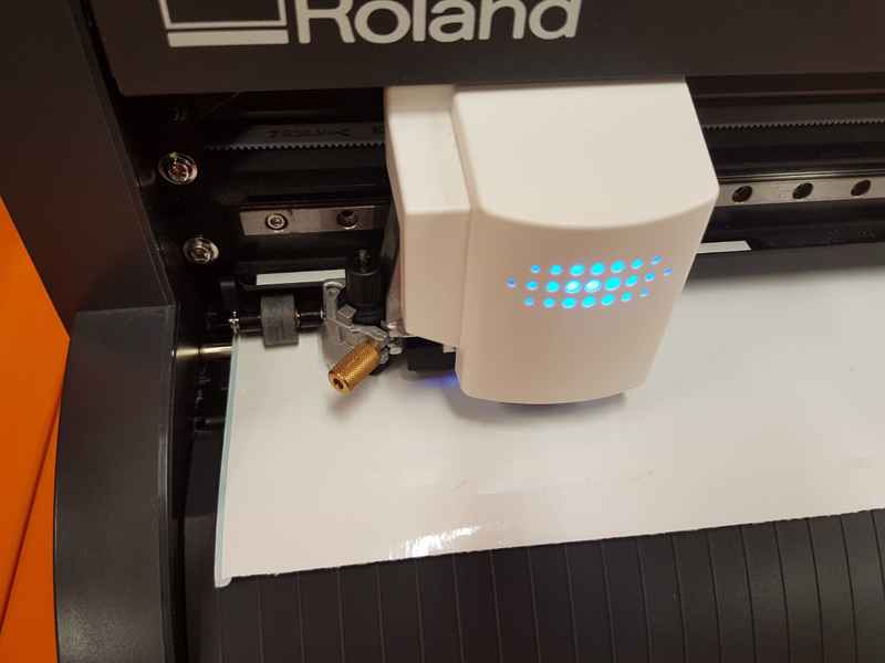
When the sticker is cut and ready the excess has to be removed and you can create positive or negative of your sticker by selecting which parts you are removing. 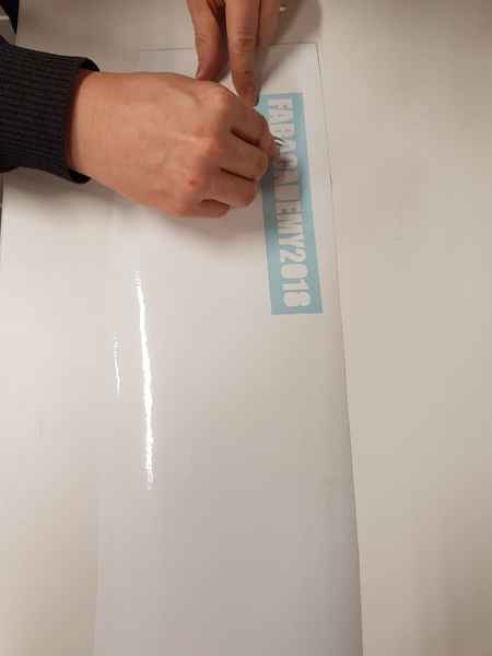
After the excess is removed, you can move the sticker with special material, which is meant for that. It does not stick hard to vinyl, but it sticks hard enough to make the transfer possible. 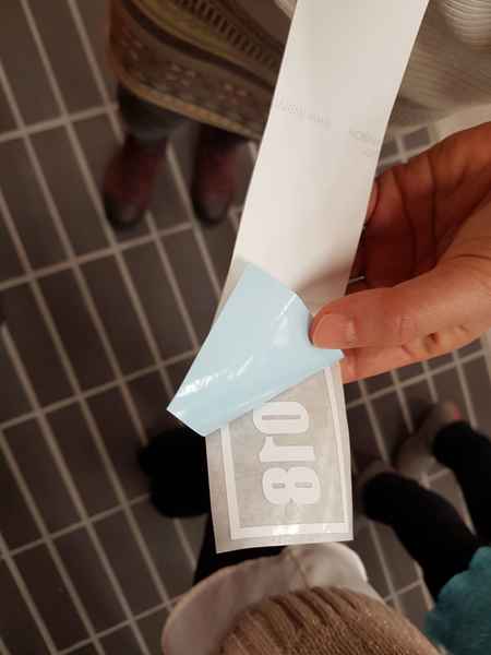


I used Inkscape to trace the lines of the picture to make it into vector graphics. I used the edge detection tool with 0.550 treshold and didn't fill the area.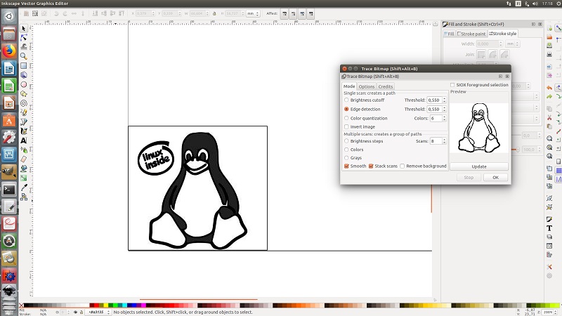
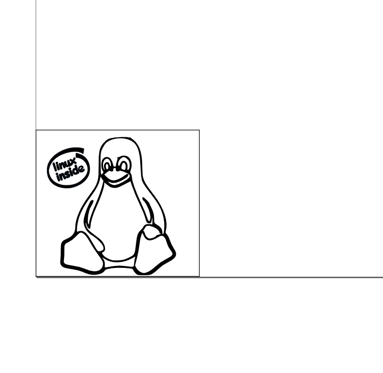
I improved the graphics a little, removed the fill between the lines and the final image for vinyl cutter looked like this: 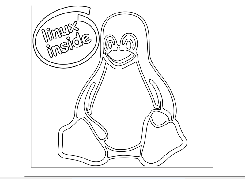
Laser cutting
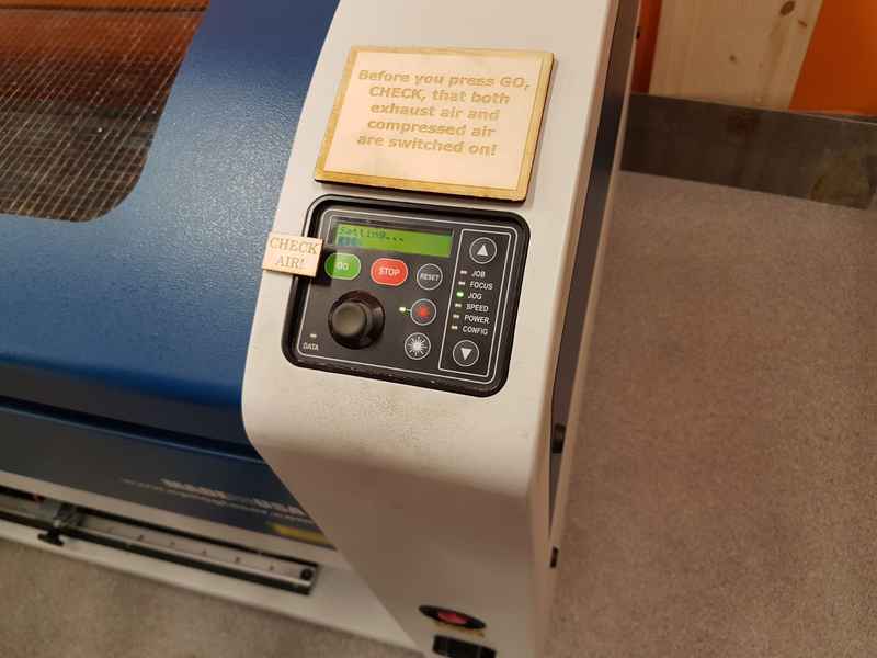
We started to practice using laser cutter with our whole group in the morning of 8.2.2018. I got the honors to be the test user, because I had no previous experince with the machine. The laser cutter I used we used in the group work is the same as I used in the individual task Epilog Laser Fusion 75W CO2. 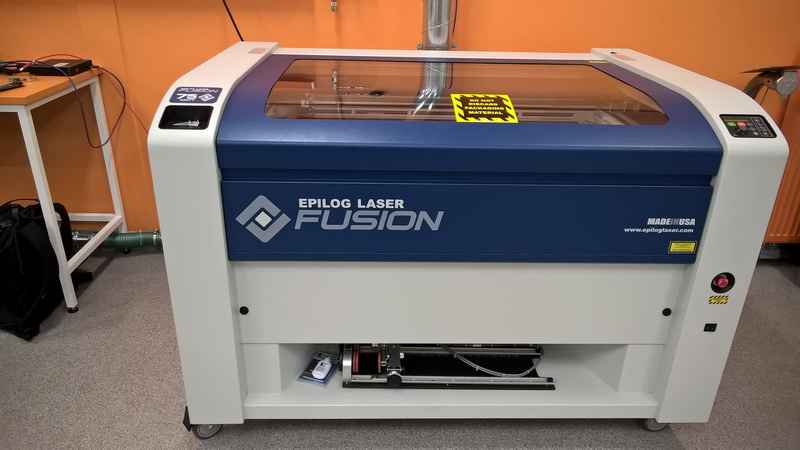
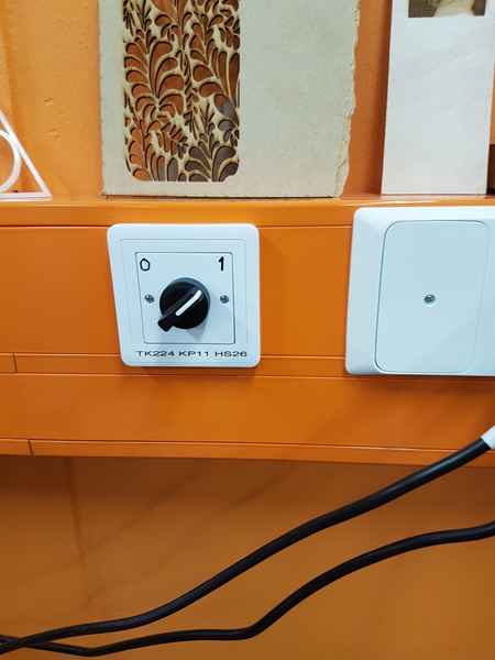
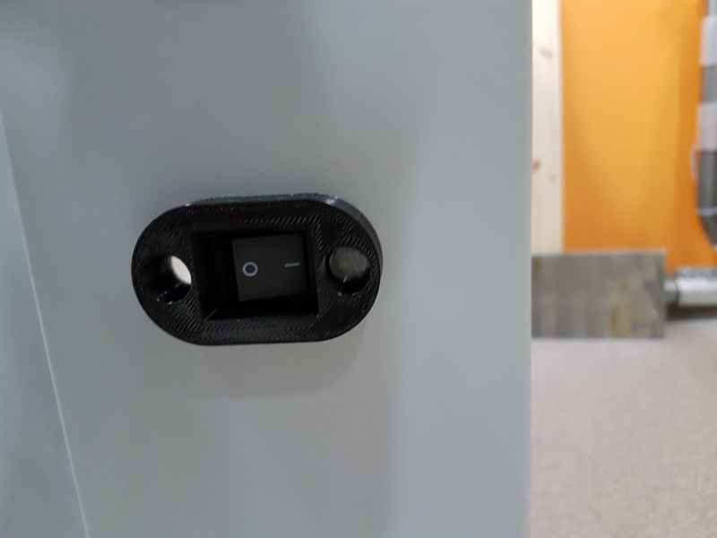
On/Off button for the laser cutter in on its side and you switch it on.
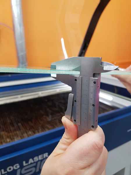
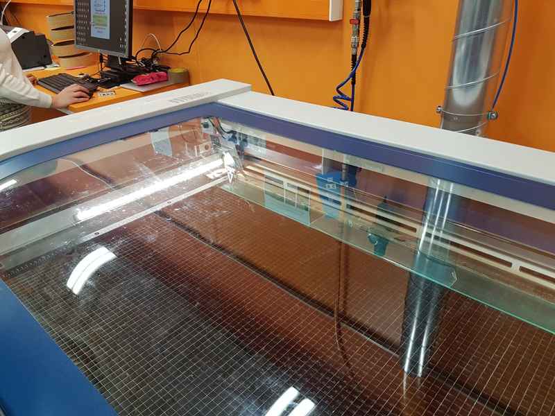
Materials for the laser cutter I used this week are acrylic plastic and MDF board. The material thickness needs to be measured to be able to setup machine correctly.
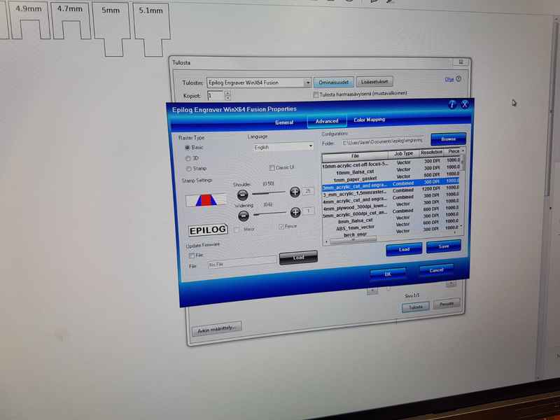
The cutting properties for each material can be selected in the advanced menu for the cutting parameters. There are a lot of different cutting parameters existing for the different materials and material thicknesses already, so you don't have to make a guess for the initial setup. You have to load the selected parameters for the cutting. I selected the 3 mm acrylic as a material for my own project.
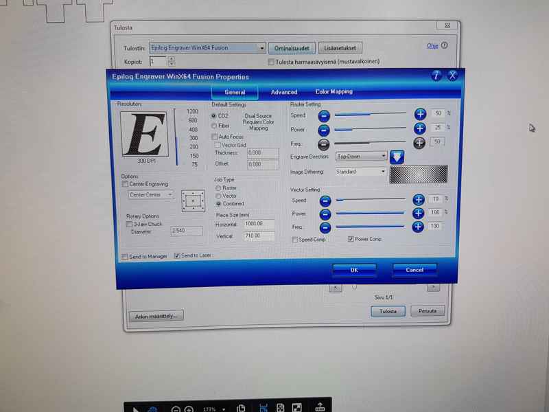
After you have loaded the the cutting parameters, you can see the settings in the general menu. There you can modify the settings for speed, power and frequency and wether you wish to start cutting from the center point or not and to select the job type for raster, vector or combined work. Raster and vector parameters are controlled individually. In the Color Mapping menu, you can select different settings for different colors, which enables you to make nice carvings. For my part, I used the Vector job type and the Speed was 10 % (Speed in the initial setup for 3 mm acrylic was 8 %, but in the group work we saw that with 10 % there was less soot on the acrylic), Power 100 % and Frequency 100.
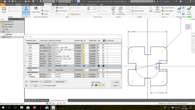
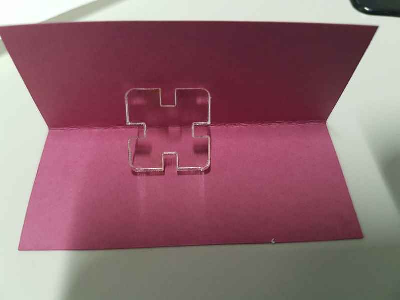
I created a simple piece for the assignment with Autodesk Inventor 2018 Professional. At first, I created a square and then a joint in it and then I rotated the joint on all sides and created fillets on the corners. I created user parameters for kerf and thickness, which I used then to control all the model parameters. The kerf is 0.1 mm and thickness 3 mm. The joint width is thickness - 2*kerf and lenght is depth + 1 mm - kerf. Since the piece is square shaped its sides are equal. The length is 7*(depth of the joint - 2*kerf)+2*kerf.
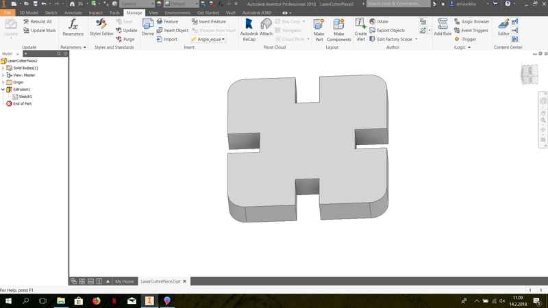
The final piece is extruded to make it a part.
In the Inventor, I created new drawing to get the pdf of the face. In the Inventor, I put the thickness of the line to 0.02 mm and created the pdf. Then I moved to laser cutter to cut the drawing.
The laser needs to be focused on the surface of the material. You have to insert the triangle on the laser, select the FOCUS from the menu and then move the cutting table with joystick until the triangle barely touches the material surface.
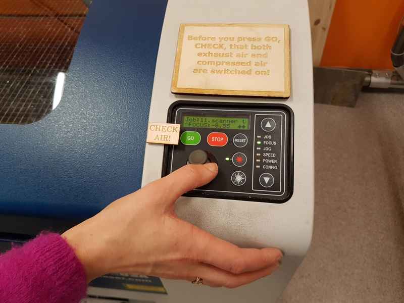
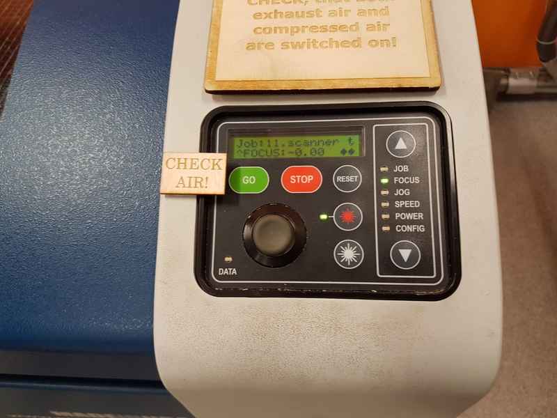
After you are happy with the position, you have to press the joystick to set the focus and on the LCD it reads, FOCUS:-0.00.
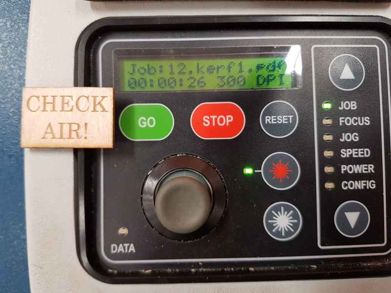
After focusing, you have to move the laser on the spot, where you wish to start cutting. You select the JOG from the menu and move the laser with joystick to the desired position. Press the joystick down to setup the position. It says setting... and the position goes to 0.00 0.00 or close to that.
Select the JOB from the menu and press GO to start cutting.
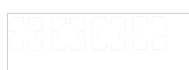
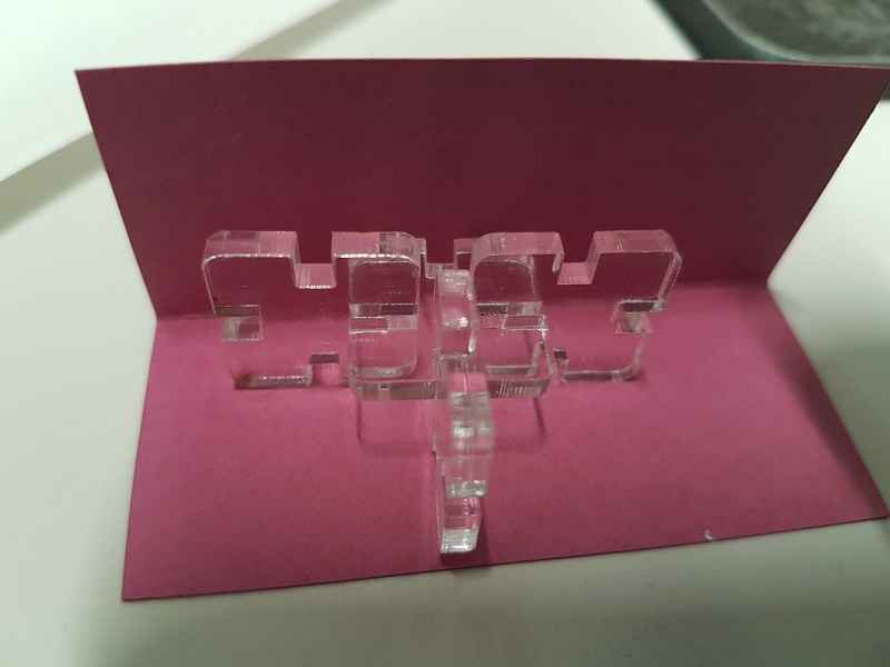
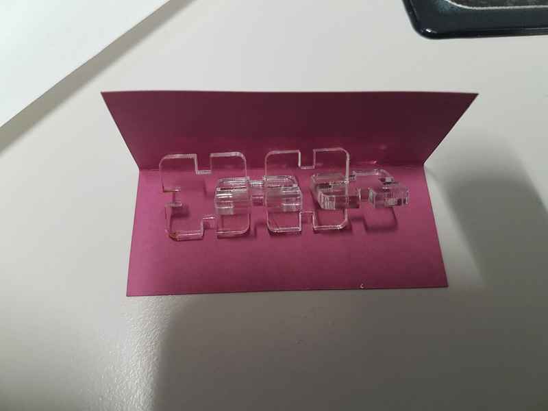
I created four pieces, which are identical to each other and can be connected on all sides. The pieces fit perfectly together and can be used to create different shapes. The cut worked in the first run, because we made the group work before the individual work and I got the kerf measurements for my project.
Tux.svg Tux logo for vinyl cutter
LaserCutterPiece.ipt Autodesk Inventor file for the laser cutting
LaserCutterPiece.pdf PDF file for the laser cutter
Group assignment
We started to create different puzzle pieces, where we test different values on the male and female pieces. Megumi started to work on the Inkscape to create the pieces and I started to document the process. 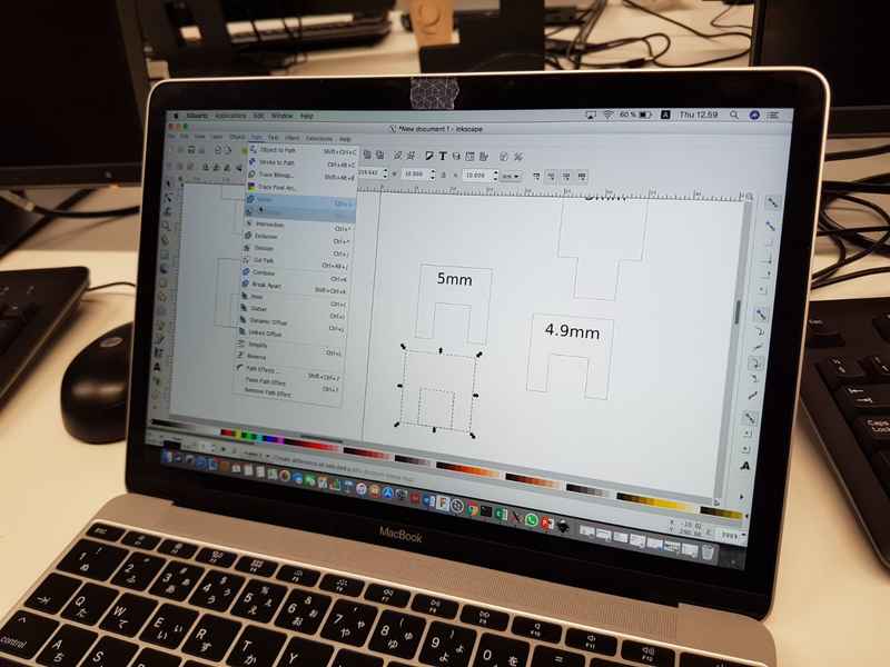
The pieces are presented in figures. For the cutting we used the lasercutter Epilog Laser Fusion 75 W. Kati, Marta and Megumi had used the lasercutter before and taught me the use of the machine. I started to work as an operator, so I could learn to use it as well. The first test we made with 3 mm acrylic. The laser was focused on the part and the origo was set in the upper left corner of the material. The cutting was set with a pdf file and we started to cut the material. After each cut, we changed the origo position to follow the last one and switched the file. 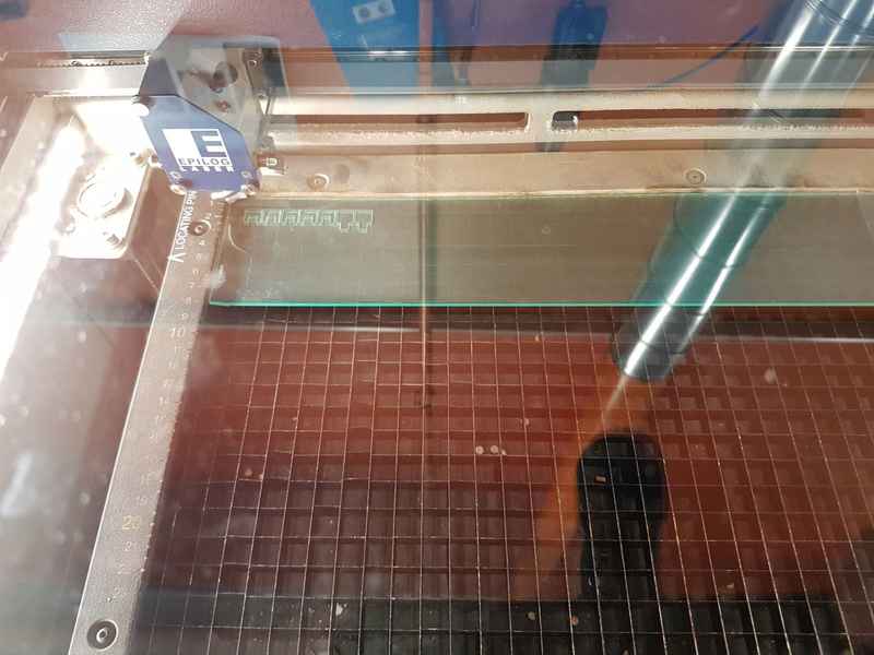
The acrylic started to show flames when the speed was 6 %, the recommended value in the lasercutter was 8 %, but we found in the manual that the value for the 3 mm acrylic should be 15 %. The problem with the recommended value was, that laser didn’t go through the material and the same problem was with 12 % case. 10 % was the value where it was hard to remove, but still went totally through. The second material was MDF 3 mm. Our parts were so small that in the case of MDF the parts started dropping through the mesh and we had to ”fish” them through the mesh after we finished cutting. 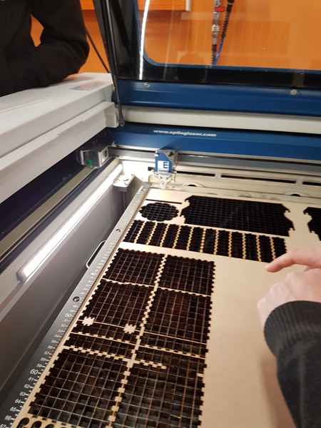
The best fit for the pieces is between the 5 mm and 4.7 mm with both materials. It seems that the best fit was universally between the 5 mm and 4.7 mm pieces. The 5.1 mm piece broke the 4.7 mm piece, so we can say that it was too big and required too much force to make them fit. The joint parts are measured with caliber to find the accurate value for the thickness. We chose to change the value in the female pieces, but it would have been easier to measure, if we changed the male pieces. 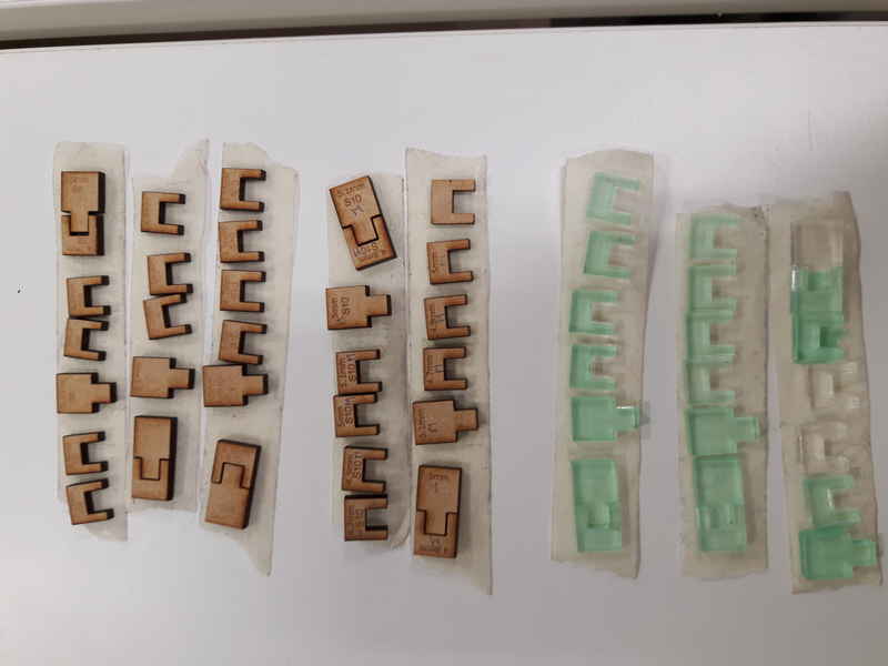
After a little bit of thinking, we decided to make the measurements from the outer side of the pieces. The kerf would be the half of the difference to the given value 10 mm. We chose the corner pieces for the measurement. The kerf changes with different materials and different settings and the caliber also affects the results. We had two different calibers and we could see clearly the difference between the tools. The difference was systematic and always in the same direction. To consider how the position affects the kerf, measurements were also done with different pieces in the same test set. The documentation and measurements took a lot of time, but we wanted to be thorough with the given task.
If we had to start from the beginning, we would change the male pieces, because we couldn’t measure the kerf easily from the female pieces.
We decided to create a simple webpage for our project and present our results there Group site. The files for the cutting and results are shared there.