Assignment 5: Electronics Production
Assignment:
group assignment: characterize the specifications of your PCB production process
individual assignment: make an in-circuit programmer by milling the PCB, then optionally trying other processes
ATtiny45
Tomás Jonathan Brian Zaerc
ATtiny44
Ali Valentin Andy David
PCB production process
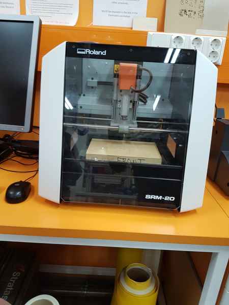
We started to practice using the milling machine Roland SRM-20 with our whole group in the noon of 15.2.2018.
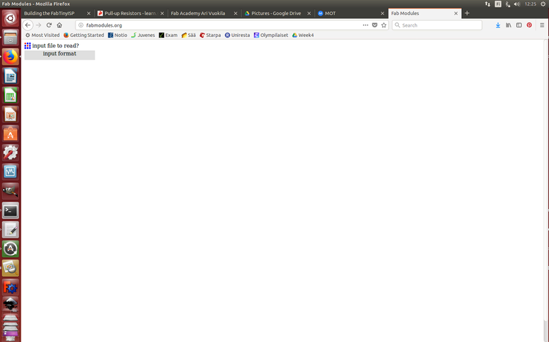
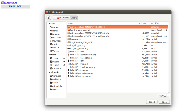
Because I use Brians design, I downloaded the trace.png and outline cutout.png images (1000 dpi) from his page. We started with trace file. At first you select input and in there image (.png)
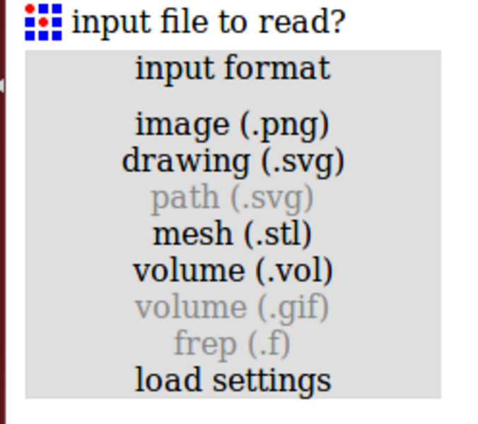
Fabmodules presents the traces image and adds new selections. 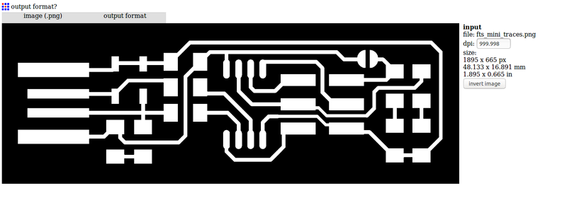
Next step is to select output format. The selected format is Roland mill (.rml). 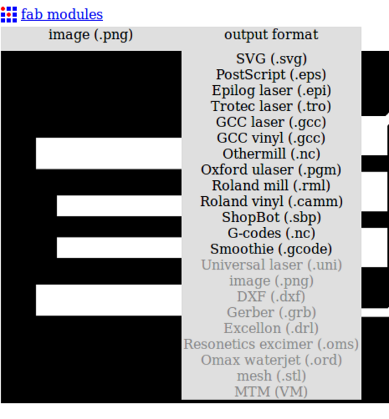
This selection also adds new options and we have to select the process, which is PCB traces (1/64). 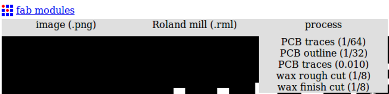
Now that we have all the major selections ready we move to output selection and select the machine SRM-20 from the drop down list. 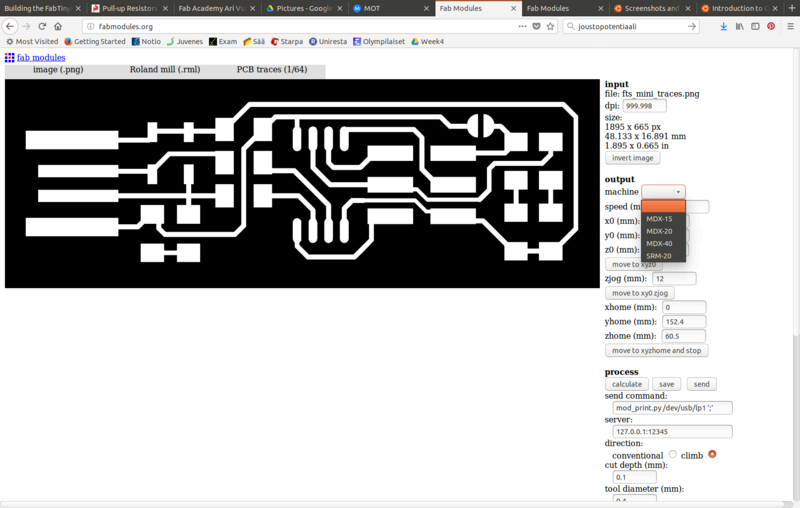
After that all the x0, y0 and z0 (mm) are to be set to zeros. 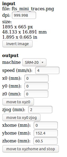
The only thing left to change is the cut depth (mm) in the process, which is set to 0.13 mm. Because we have v-shaped tool, the cut depth affects width of the cut. 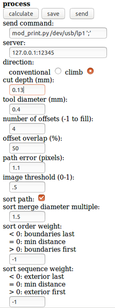
With a few tests, 0.13 mm seemed to make good cut, with only little bit of excess copper left on the PCB, but the connections still stayed thick enough. Now select calculate from the process and it creates automatically the file for PCB tracing. 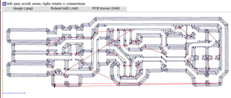
Use save button to save the file on your computer. 
Same things are made for the outline cutting file with small changes. Input and output formats are the same, but the process is the PCB outline (1/32). Similarly to traces, the machine is SRM-20 and x0, y0 and z0 (mm) are all set to zeros. The tool diameter is set to 1 mm, which is the tool diameter in our Fablab. 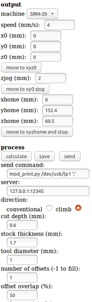
Now press calculate and save the produced file on your computer. All the outlines has to be continuous black lines to be cut out. In a groupwork, we had too thin line for our tool, which created the problem that the milling machine did not cut one line out and we had to create new outline cutting file with tool diameter of 0.4 mm to be able to cut the line. 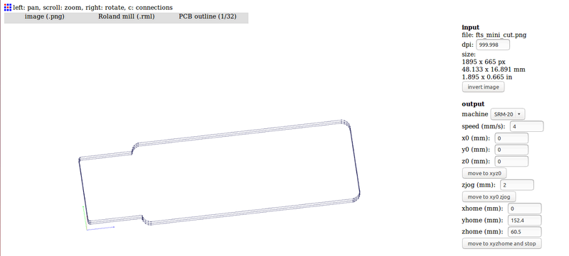
Now the files are ready for the milling machine.
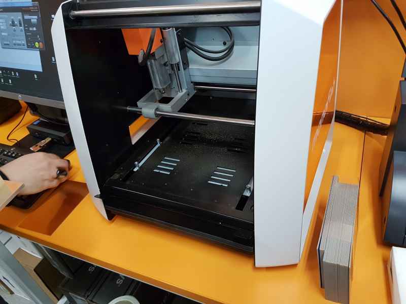
The milling machine is turned on from the upper right corner on top of the machine. 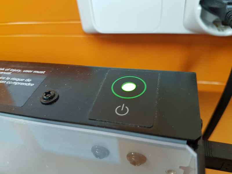
The material for the PCB we used was FR1. To get the FR1 ready for milling, you have to remove the protecting blue sticker from its surface. 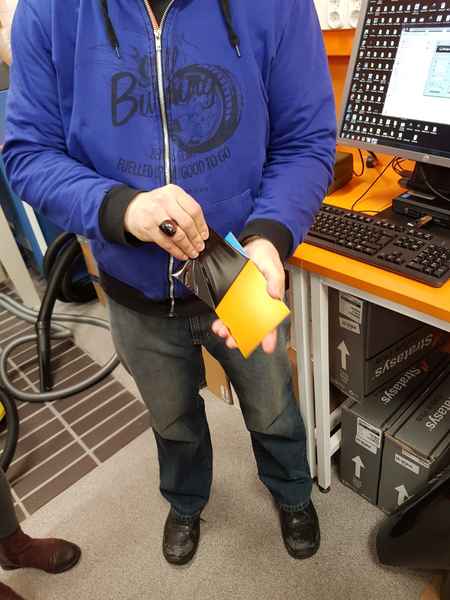
To get the FR1 in the milling machine, move the bottom plate in view position and remove four screws holding the bottom plate and take it out from the machine. 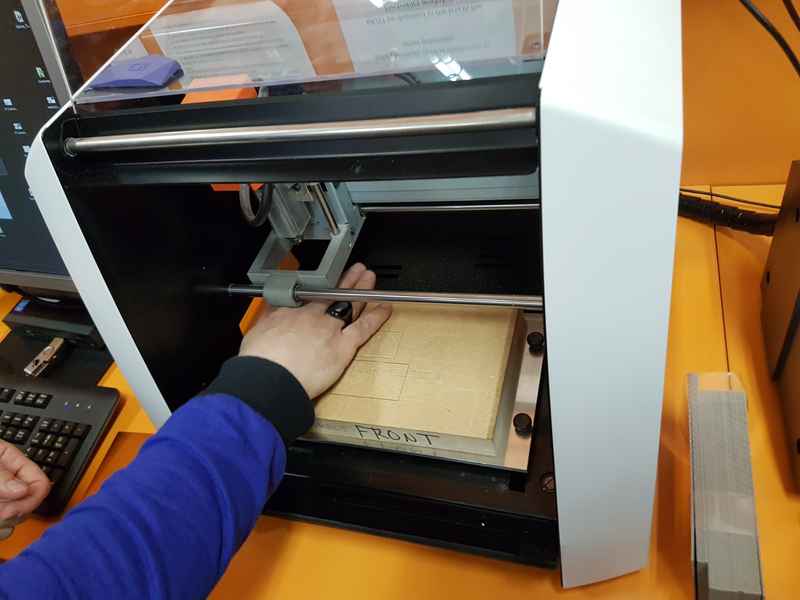
Use two-sided tape to attach the board on the bottom plate. Whole bottom of the board should be covered with tape to avoid bending and moving of the board during the milling process. 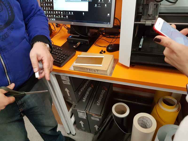
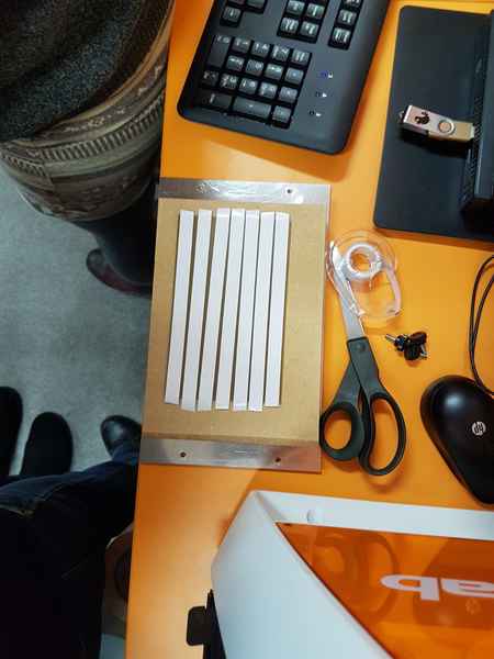
Attach the board in the lower left corner of the bottom plate about 1 cm from the sides. 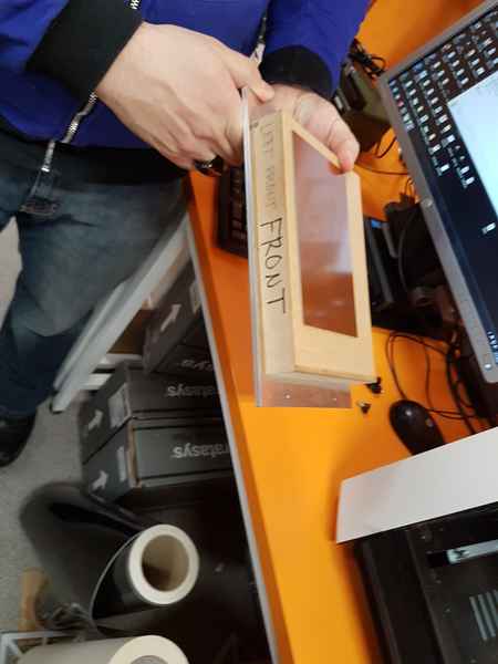
Put the bottom plate back to its place and the screw the screws back. 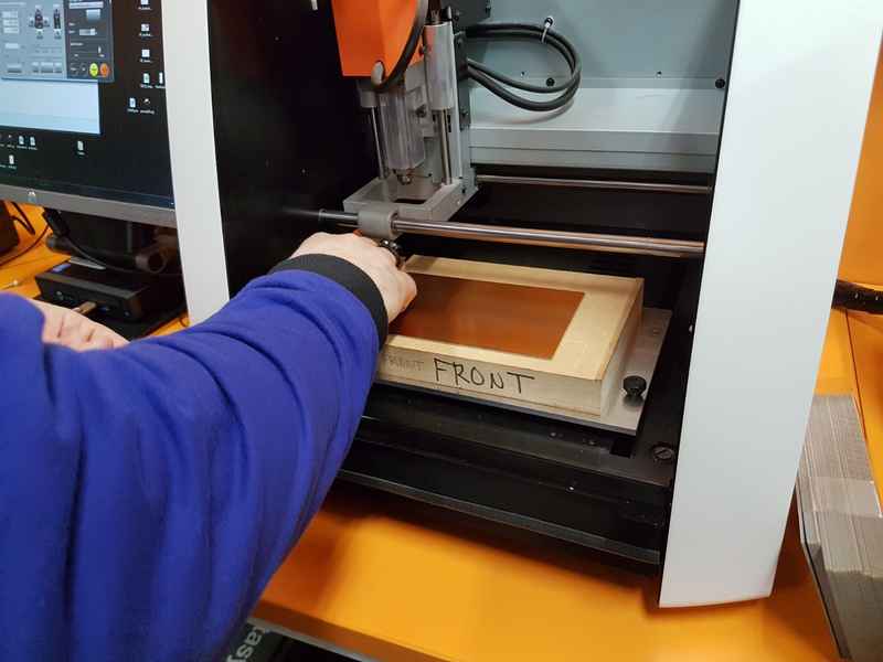
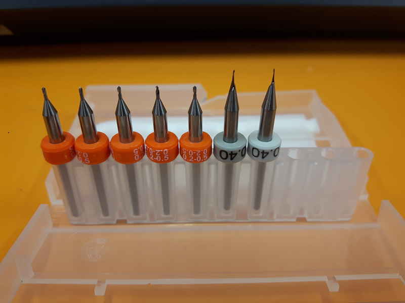
We have two different types of tools for the trace milling in Oulu Fablab. In the photo, the 0.4 mm flat tip tool is shown, but in Oulu v-shaped tools are preferred, because they last a lot longer. The 0.4 mm flat tip tool was used in the demonstration of the milling machine operation. 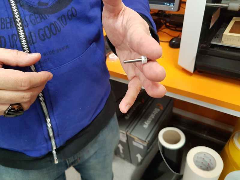
When the tool is inserted in the machine you need a hex key. The screw that holds the tool in place is a hexagon socket screw, which need to be loosen and tighten with the hex key. 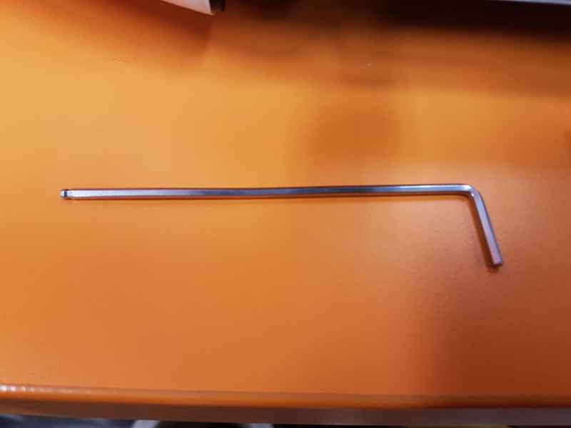
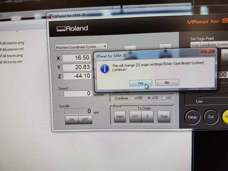
After the tool is in the machine, you have to move the tool tip to your preferred origo point. Use VPanel for SRM-20 to move the location. Pressing arrows (-x, +x, -y, +y, -z and +z) with your mouse, you can select the direction where the tool is moved. The movement can be continuous or you can select the step size 1 mm, 100 µm or 10 µm. In the upper right corner there is a setting for set origin point. 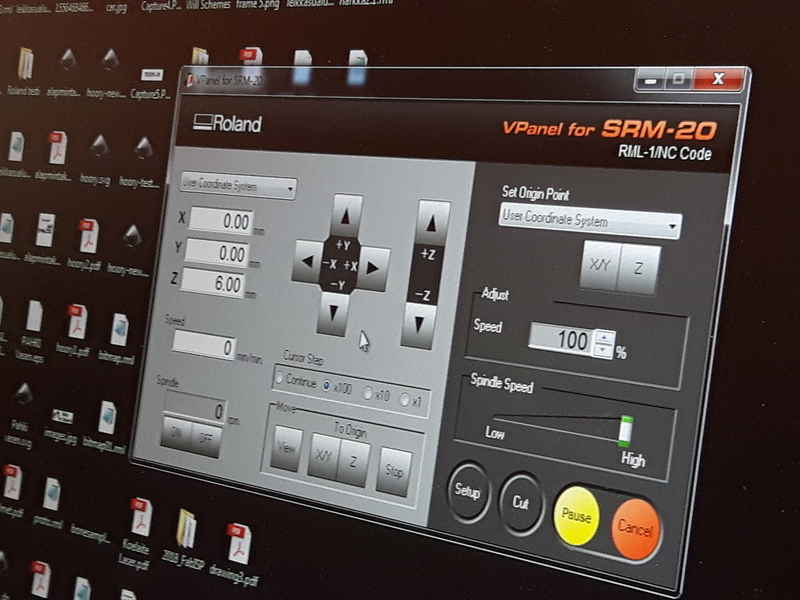
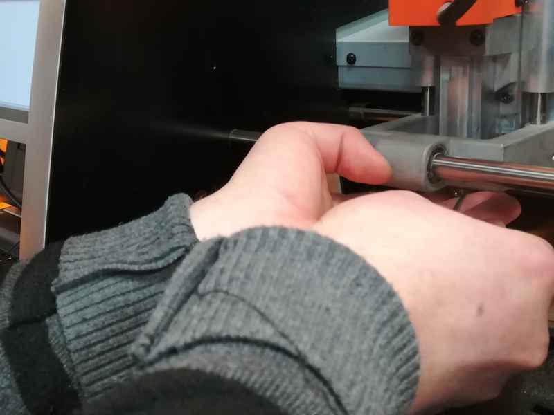
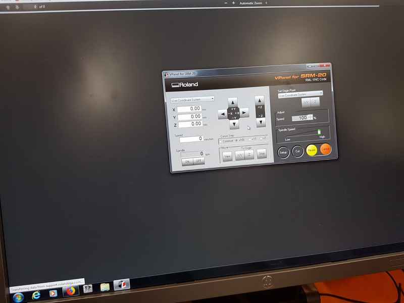
From there choose User Coordinate System. When you are happy with the origin point for x/y-axises, press x/y under the set origin point. Then lower the tool close to the surface of board, loosen the screw which holds the tool and lower the tool on the board surface. While holding the tool in place, tighten the screw and from the VPanel set origin point for the z-axis. User coordinate system will show all zeros when origin point is set. 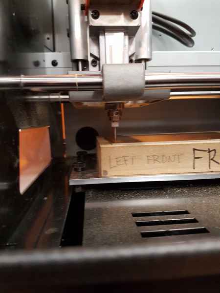
When origin point is set, move the tool up for example 500 µm. Then you select Cut from VPanel, delete all projects, select your file for tracing and press Output to start tracing the board. After tracing is finished, you have to vacuum the dust off and change the tool for cutting tool (1 mm tool in our Fablab). 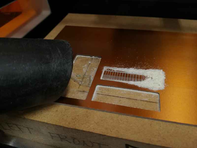
You have to once again set the origin point for the z-axis, because you have switched the tool. The x and y axes are remaining the same. Move the tool up for example 500 µm. Press cut from VPanel when all is ready, delete all projects, select the outline cutting file and press Output to start cutting the outlines. 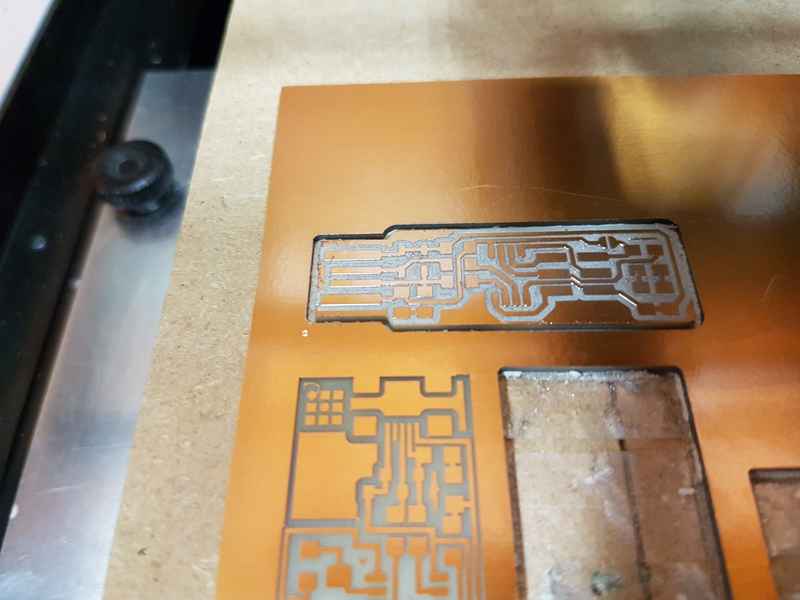
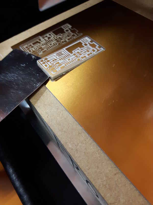
When the cutting is finished vacuum the dust and remove the PCB with spattle. 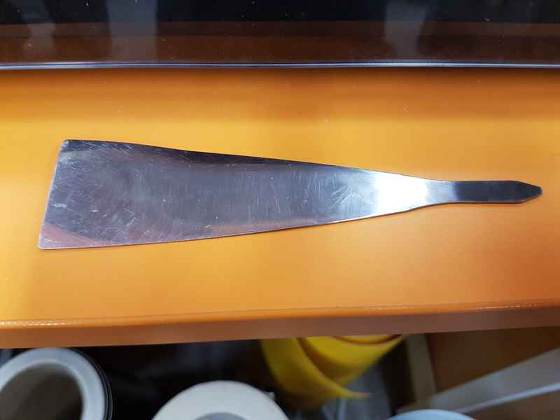
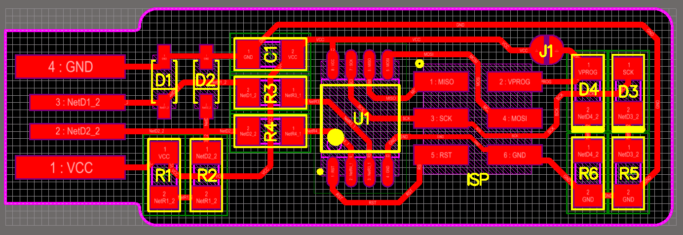
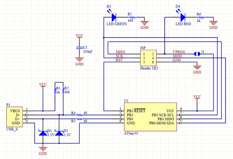
FabISP
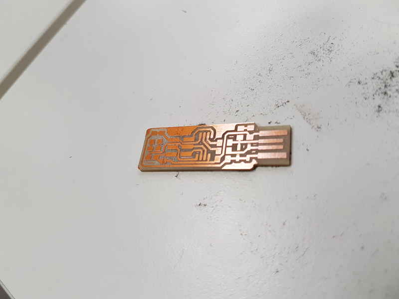
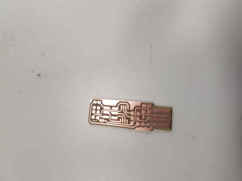
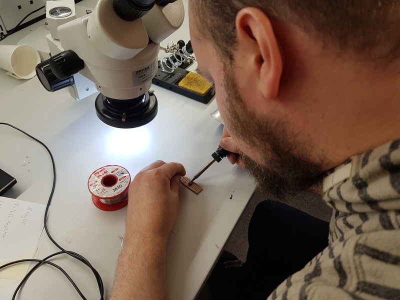
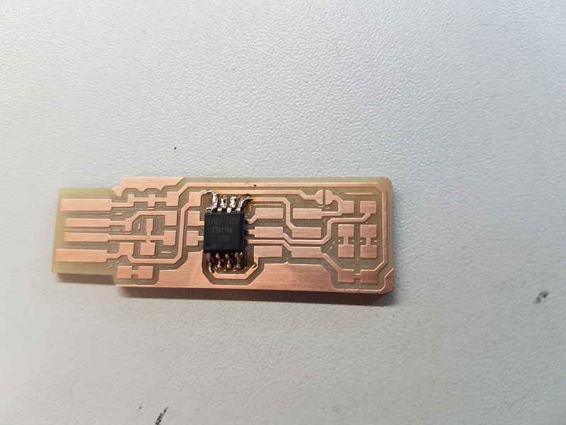
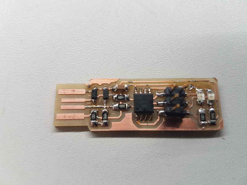
Extra copper is removed from the board with a knife. The copper has to be removed from the usb part, because it would create problems when the programmer is used.
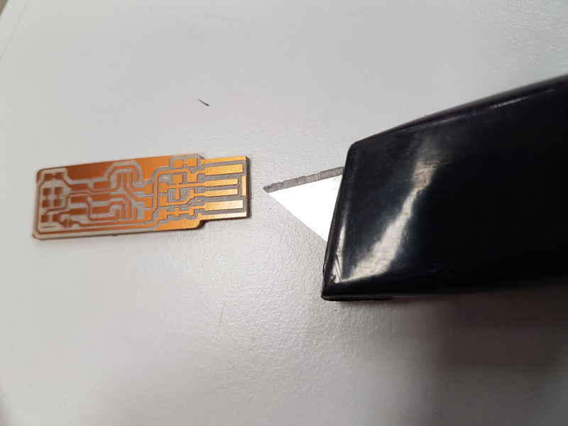
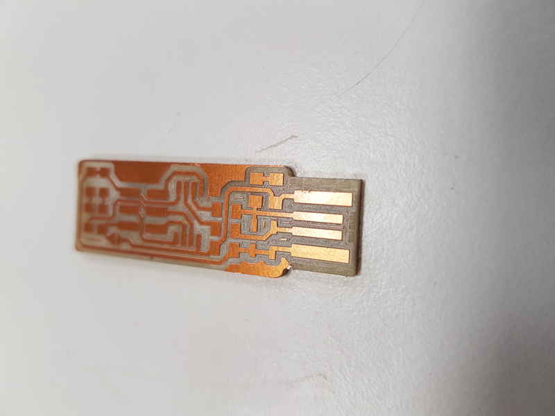
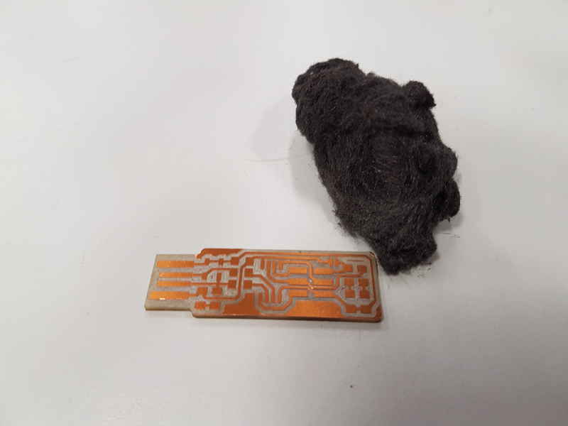
In this image half of the layer is removed and the difference in light reflectiveness is a large one.
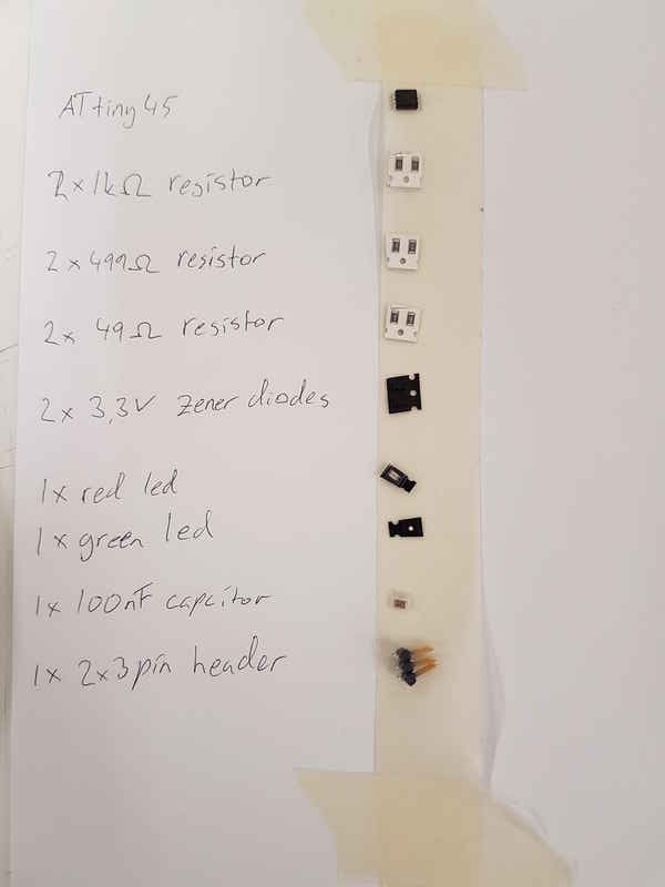
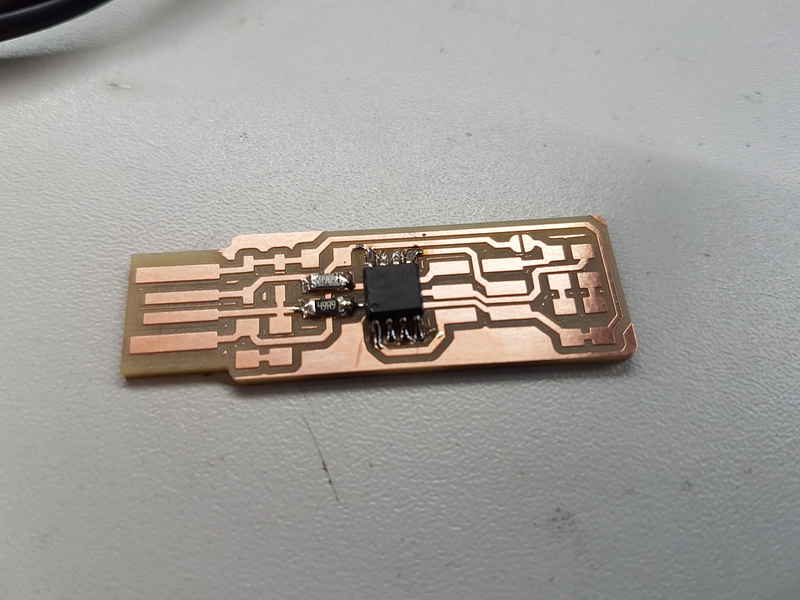
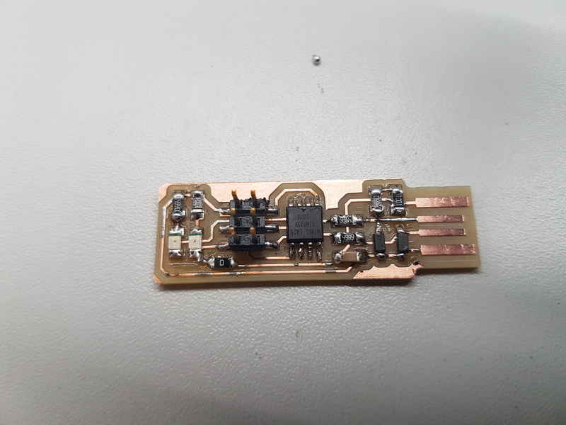
The components are collected from the storage room and put on a tape on a paper next to its name to make it easier to collect all the necessary components and to be able to see quickly which component is which when you are soldering. The organizing system was suggested by our instructors.
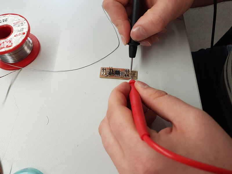
I measured the ISP to ensure that there are no short circuit problems. My ISP passed the test.
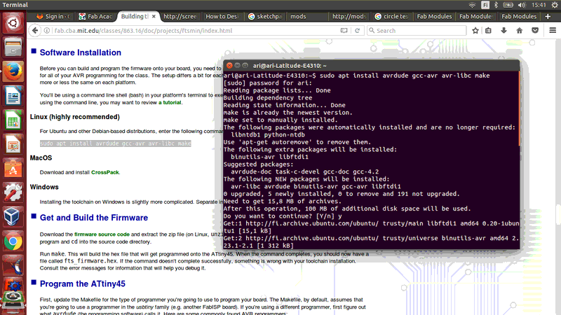
> sudo apt-get install avrdude gcc-avr avr-libc make
Next you have to download the files for the firmware source code and extract the zip and in terminal move to the source code directory. Run command
> make
which builds the hex file that is installed in the ATtiny45. Because I used the ATtiny45 nothing needed to be changed in the Makefile, but in case you use something else it has to be defined there near the top where it says PROGRAMMER ?=usbtiny. usbtiny is changed to whatever programmer you are using. 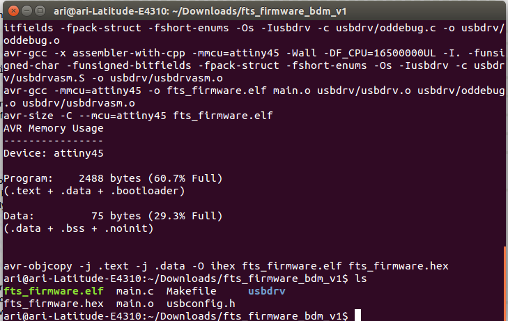
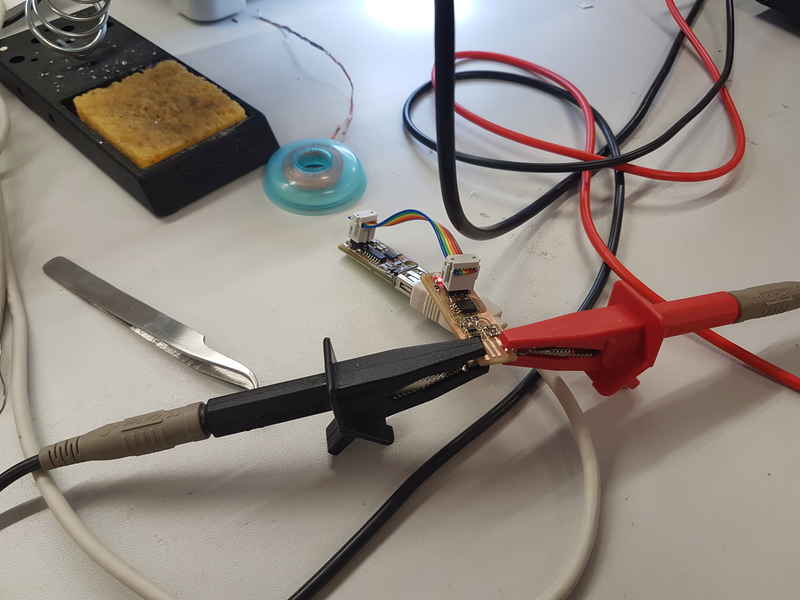
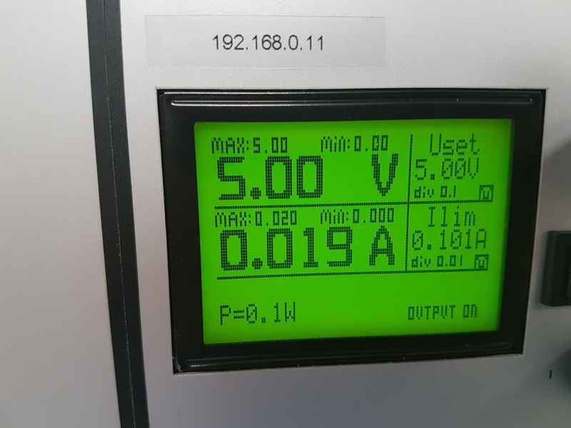
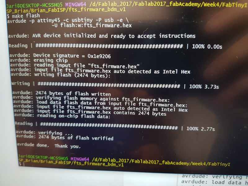
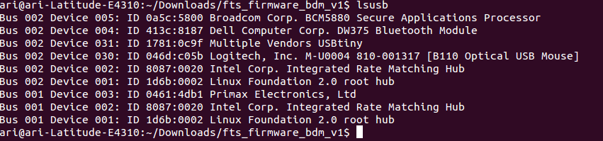
Plug the programmer, that you are using to program your programmer, in the usb and connect the programmers together with a programmer cable. It has to be connected in a way that pin 1 of the programmer is connected to your programmers pin 1 and so on. My computers usb port didn't provide power for my programmer and the led didn't lit, so it had to be connected with alligator clips to a power supply. My programmers led did light with different computer, so we knew it was working otherwise. The voltage from power supply was set to 5 V and the current was set to 0.1 A. The led was lit and it was time to install drivers in it. The command I used was
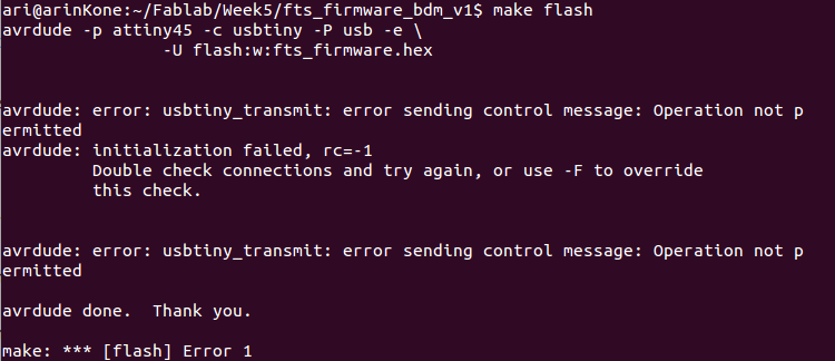
> sudo make flash
For some reason it required to be run as root. With first tries without the power supply and root command, the flashing created an error.
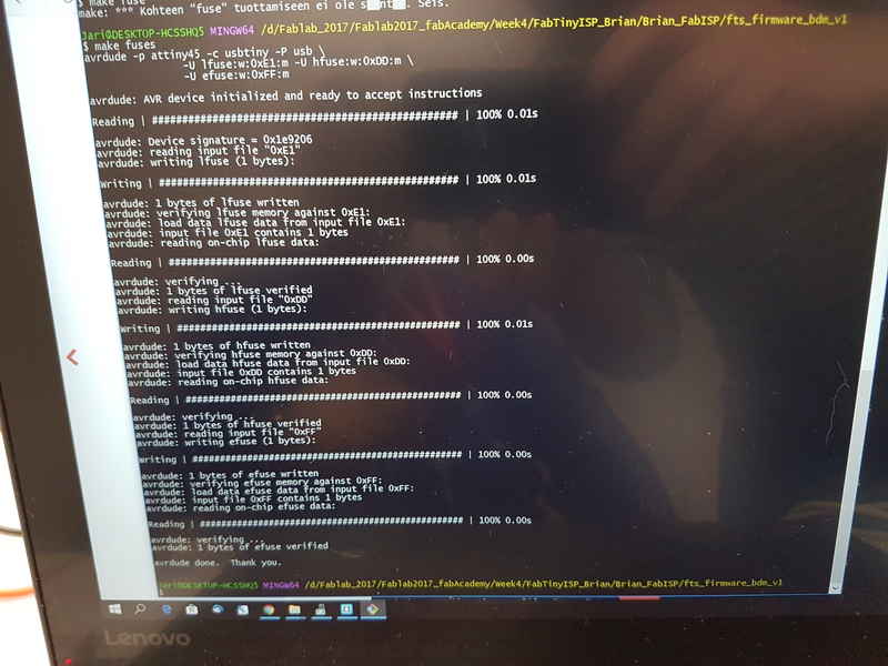
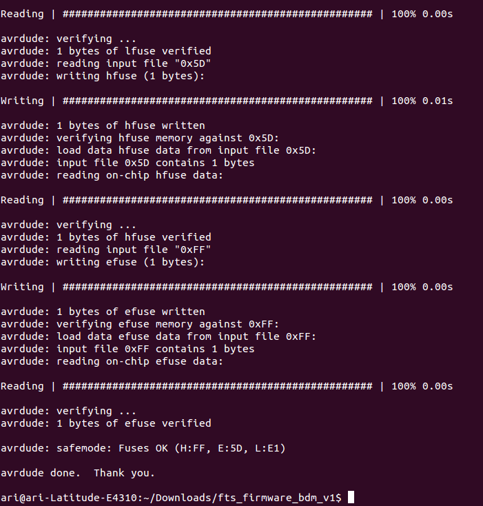
After the drivers were loaded on the ISP it was time to make the changes permanent in the device.
> make fuses
command was run, which sets the configuration fuses that control where the microcontroller gets its clock source.
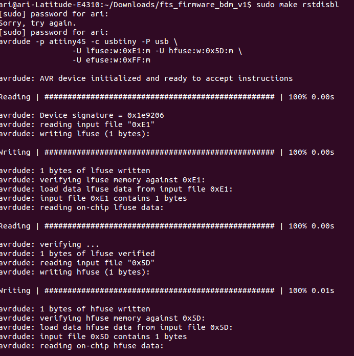
To prevent reprogramming, the reset pin is then disabled with command
> make rstdisbl
Now only thing left to do is to remove jumper from the ISP and it is ready to use for programming.
The files used in the assignment are shared below:
MillingFiles.zip Brian's images and rml files for milling.
Group assignment
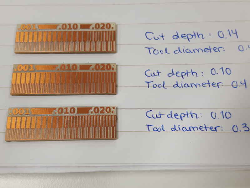
The group work consisted of machine milling of a line test. Each of us in the group produced one test milling to make sure that each of us know how to use the machine. The group work is presented in the page Electronics production group page. Our instructor Jari was really interested to know what is the real diameter of the tool with different cut depths, but because of the lack of time, we only tried a couple of setups. I had an idea that, because we use the v-shaped tool that we could change the tool diameter and see different results with different cut depths. In the fabmodules we created three different cases with cut depth of 0.14 and tool diameter or 0.4 mm, cut depth of 0.10 and tool diameter or 0.4 mm and cut depth of 0.10 and tool diameter or 0.3 mm. Jari measured the lines under microscope, but the results have not reached us yet.