Assignment 5
15.2.2018
Topic: Electronic Production
Goals of this week:
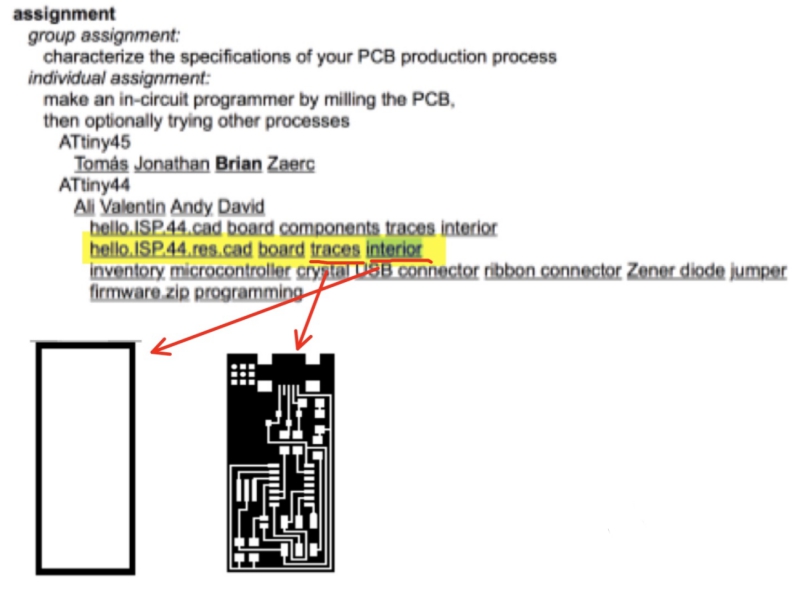
- Make an in-circuit programmer by milling the PCB, then
optionally trying other processes (Individual)
- Characterize the specifications of your PCB production process (Group) (LINK)
Preparing relevant files
Thursday, Jari, this week´s instructor, gave a comprehesive lecture for this week´s
assigment.
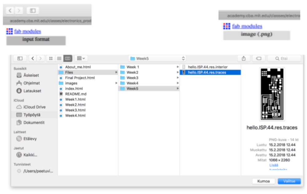
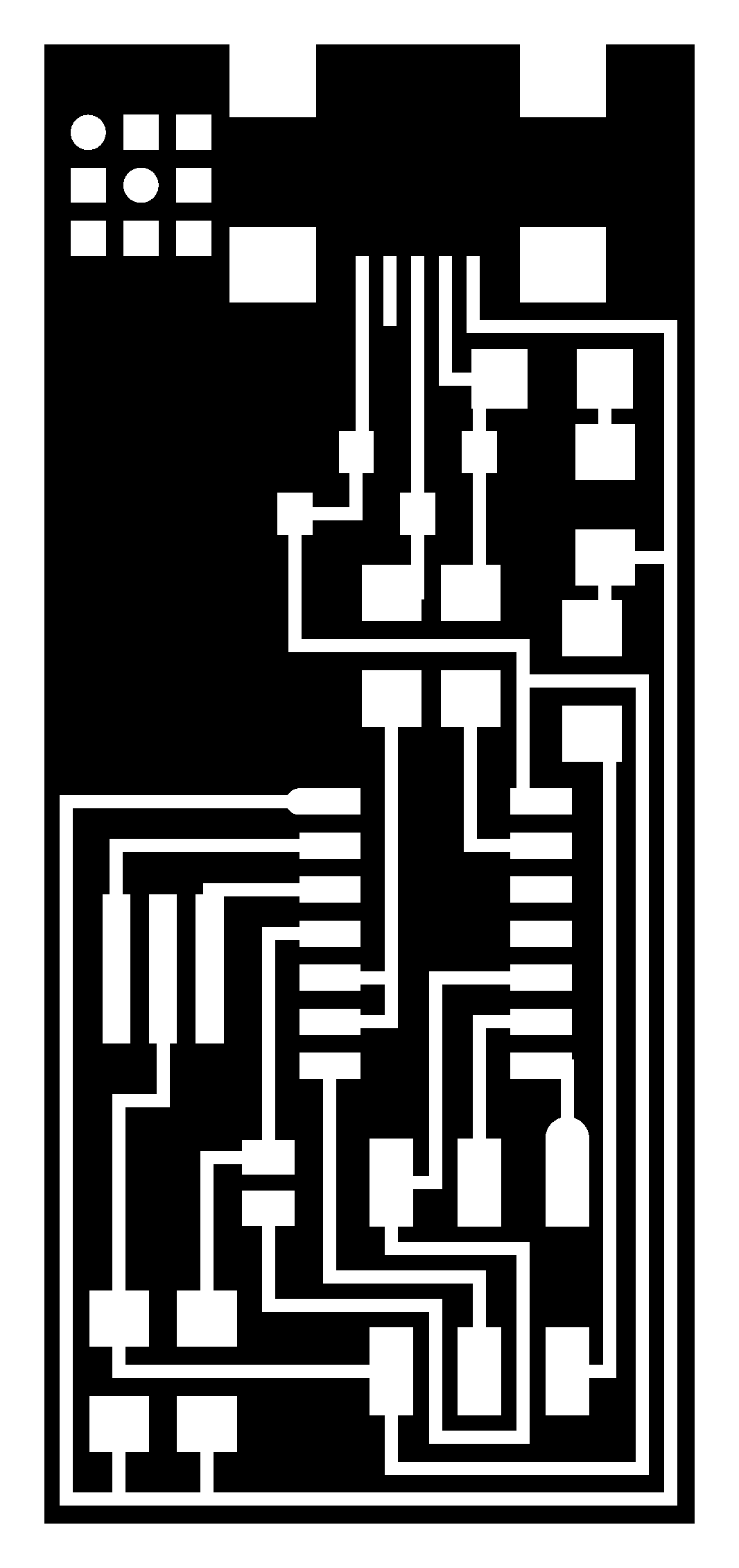
After the lecture, I started my electronic production assigment by saving hello.ISP.44
traces and interior files from this week´s assigment site to my computer as png-files:
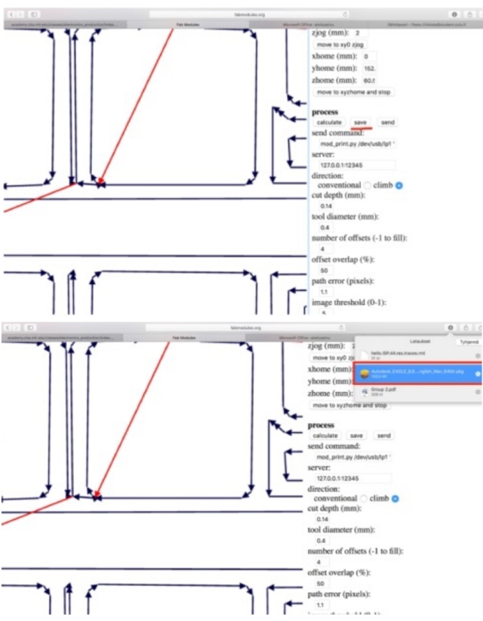
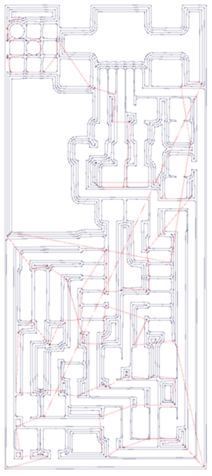
Then I went to fabmodules.org, where I created res.interior
res.interior file and res.traces file from the traces and interior files through following
procedure:
1. Choose png as a input format and choose traces
2. Choose Roland mill (.rml) as a output format.
3. Choose PCB traces (1/64) as a process
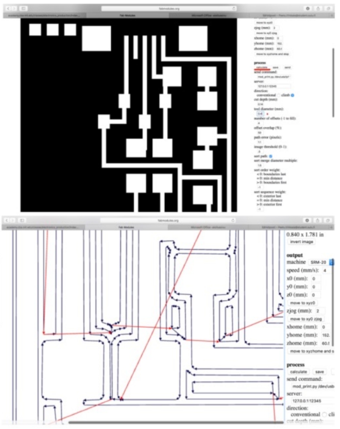
4. Modify cut depth to be 0.14 mm
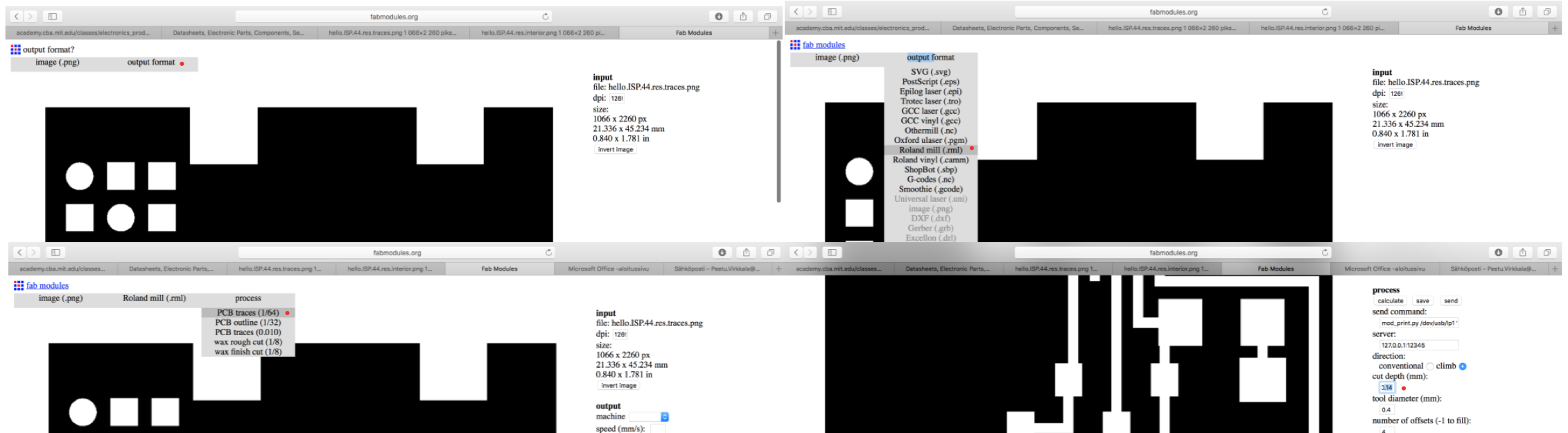
5. Calculate
6. Save as rml. file
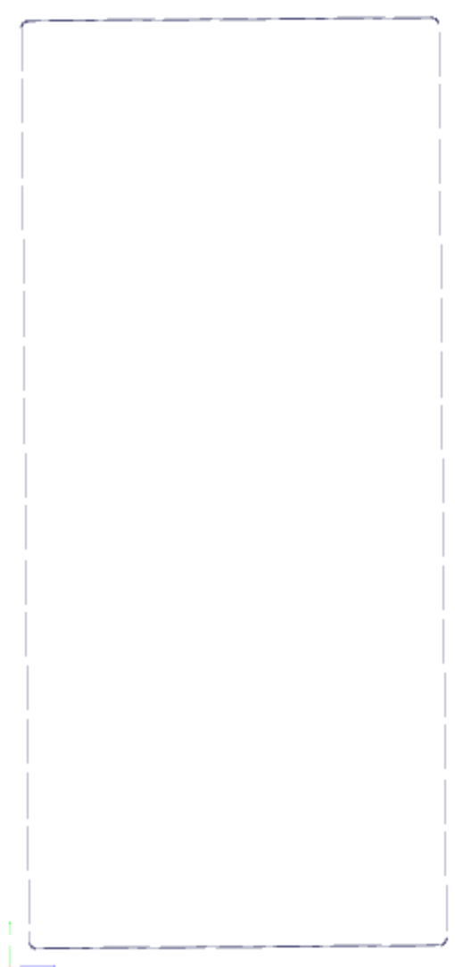
7. Repeat same processes for interior by using PCB_Outline. Change the milling
bit to 1mm and set cut depth to 0.6mm to cut through the copper plate
Cutting the board
Next, it was time to use these res. files to cut the board with Roland SRM-20 mill
through following procedure:
1. Choose copper plate
2. Remove cover sheet from the copper plate
3. To attach the copper plate to SRM-20, add double-side tapes under the copper plate
4. Stick the copper plate on the top of the SRM-20 drilling surface
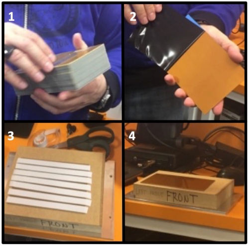
5. Put the surface right way into SRM-20, screw the bolts to the surface.
Be sure that you install the surface in correct orientation inside!
6. Choose right milling bit to be used. If you are cutting traces, use v-shape milling bit.
If you are cutting interior, use 1mm straight milling bit. We start by cutting traces
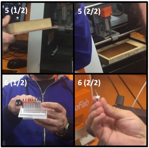
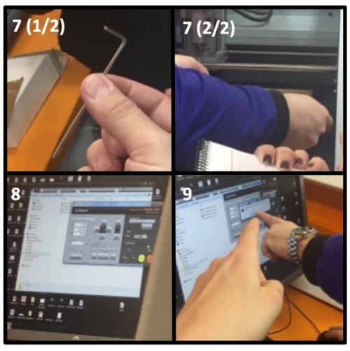
7. Screw the chosed milling bit to SRM-20 milling by using allen wrench
8. Import the cutting file to SRM-20 milling software as rml. file
9. Choose starting X and Y cordinates and zero them
10. Relase the milling bit and let it carefully to drop down to the plate
11. Screw the milling bit back and zero Z starting point.
12. Rise the drill little bit and start the milling procedure
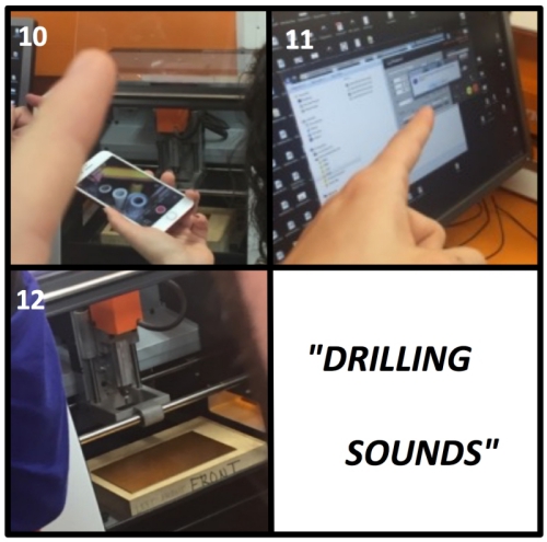
13. Execute the drilling process in SRM-20 software
-------------------------------------------------------------------------------
SRM-20 SOFTWARE (Roland v-panel):
MAIN WINDOW IN MORE DETAIL:
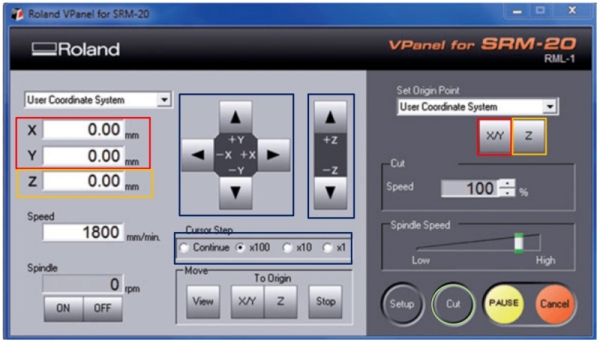
Red: X and Y cordinate values and their zeroing button. (Step 9)
Yellow: Z cordinate value and Z zeroing button. (Step 11)
Blue: Z, X and Y direction moving interface and drill moving speed. (Steps 9, 11 and 12)
Use these to move the drill
Green: "Cut" brings up the cutting window as seen below. (Step 13)
CUTTING WINDOW IN MORE DETAIL:
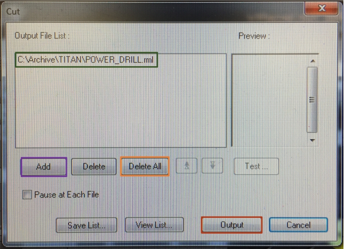
Green: File/files which the SRM-20 has been chosen to cut
Purple: "Add" adds new file to be cut with SRM-20
Orange: "Delete All" deletes all files that have been chosen to cut. "Delete" on left from it
deletes only the highlighted file
Red: "Output" starts the cutting process for chosen cutting file from the chosen origin x, y, z spot
CUTTING PROCESS IN MORE DETAIL:
- Click "Cut"
- Click "Delete All" to delete previous files
- Click "Add" to add your rml. file
- Click "Output" to start the drilling process
-------------------------------------------------------------------------------
14. When the first milling process is ready. Change the milling pit and define new Z-origin to cut interior.
When this is done, follow cutting process method with interior-file.
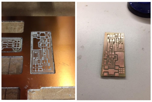
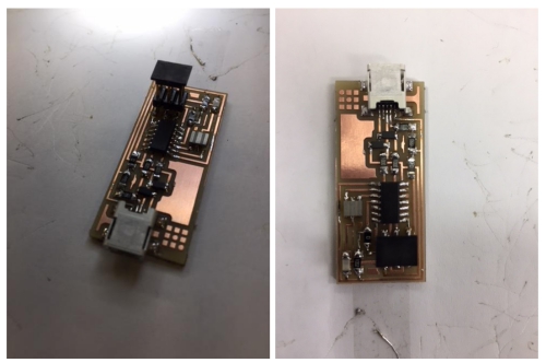
After milling both files, the end result should look like this (left). Then, the
board is cleaned with iron wool (right):
Soldering Starts!
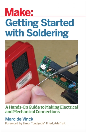
Next, it was time to solder parts to the board. Last time I soldered during the high school.
I knew the process still pretty well but decided to research more about the topic by
reading Make book related to soldering:
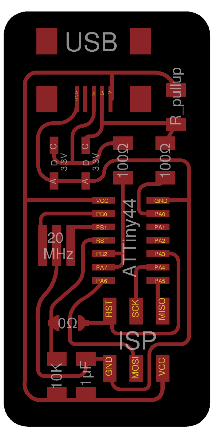
I used Ali Shtarbanov´s circuit design and followed his board blueprints:
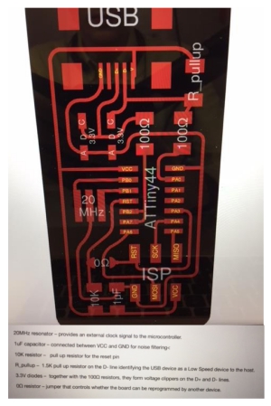
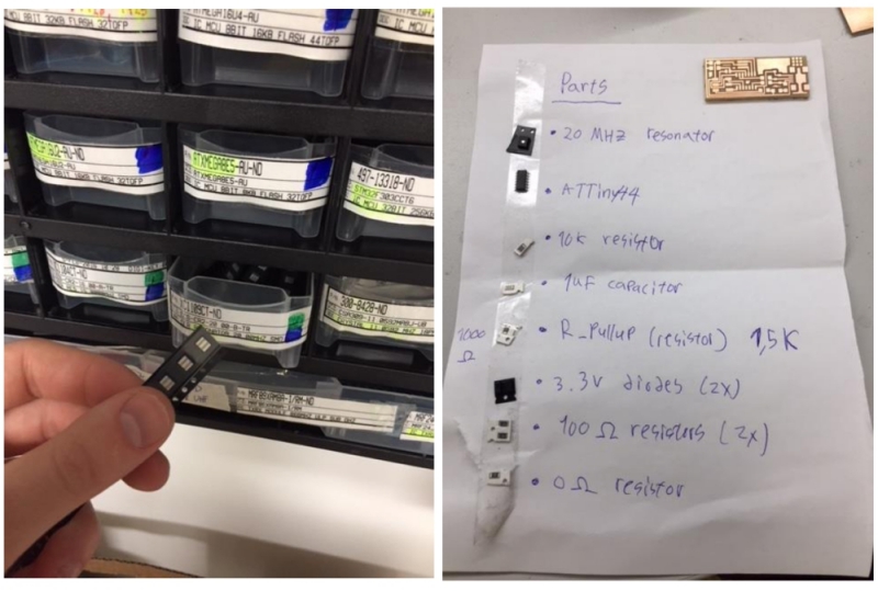
When I had analyzed his blueprint, I went to storage room and picked all required parts:
I choosed to use micro USB port and started the soldering process by first soldering it and
ATTiny44 CPU to my board. Soldering was more complicated than I thought, but I managed to solder
both parts to the board (left). When I was preparing to solder diodes to the board, I noticed that I was
using wrong blueprint at Ali´s site
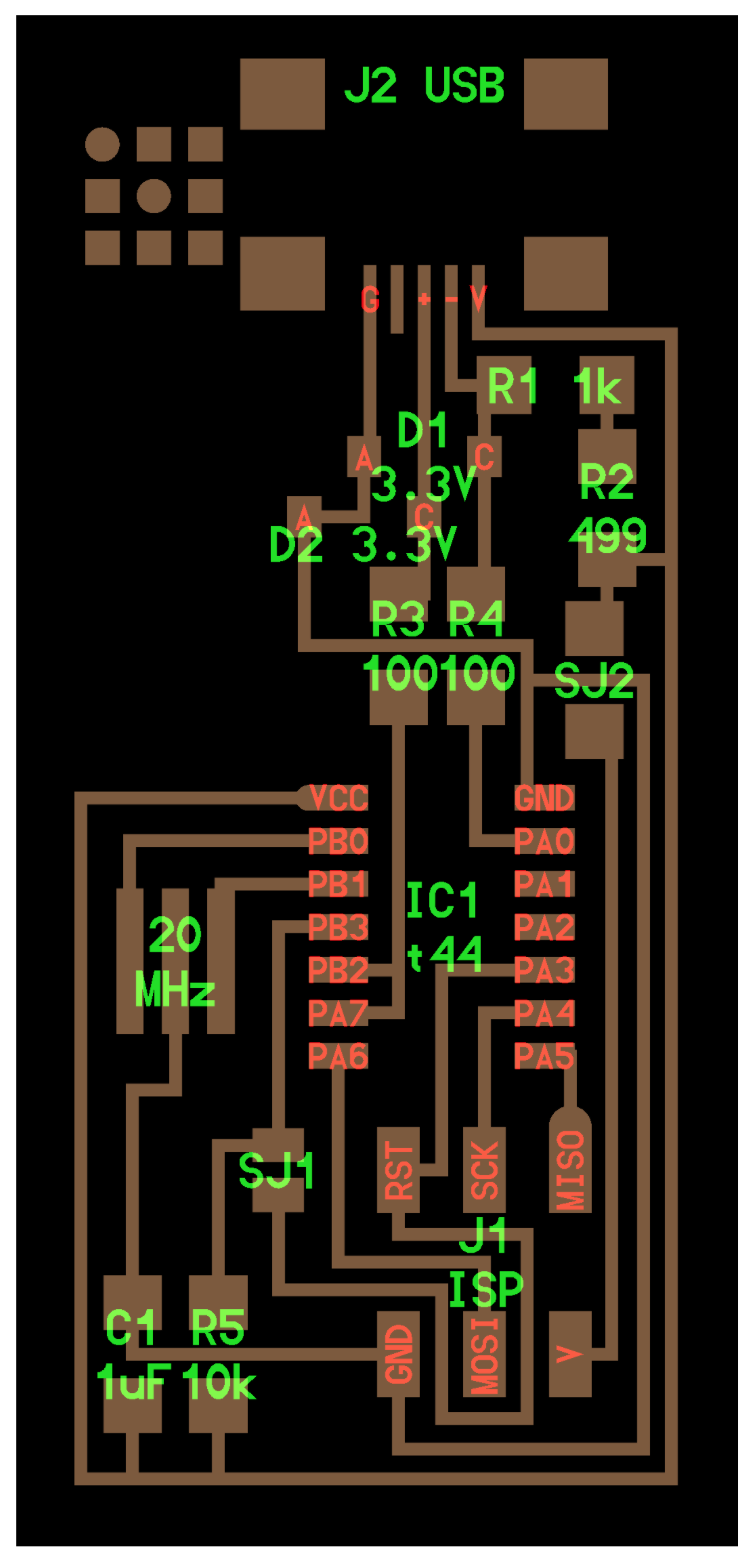
The right blueprint can be seen on the right:
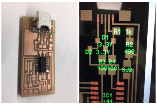
According to this new blueprint, I needed following parts to finnish my programmer board:
- J2 USB
- IC1 t44
- 2x diodes (3.3V)
- Resistor 1kΩ
- Resistor 499Ω
- 2x jumper resistor 0Ω
- 2x resistor 100Ω
- Resonator 20MHz
- Resistor 10K
- Capacitor 1uF
- ISP
I got lacking parts from the storage room and finished the soldering. Rest of the soldering was pretty
stright forward as long as you remember to solder diodes right way to the board.
-------------------------------------------------------------------------------
HOW SOLDERING IS DONE:
To solder, you need following equipment:
- 1. Safety glasses
- 2. Soldering iron with stand
- 3. Wire cutters
- 4. Damp sponge
- 5. Solder
Soldering process goes forward as follow:
- 1: Heat up the soldering iron
- 2. Warm board and solderable part with the soldering iron
- 3. Push piece of solder to connection between the part and the board
- 4. Pull remaining solder out when you are happy with the results
- 5. Add extra soldering if needed
-------------------------------------------------------------------------------
My finished board looked nice. I was happy about the end result:
Soldering was exciting task and I learned to read blueprints and build according to them.
In future, I try to run the code through the board and test what I can do. (Done during the Week 9)
FILES made THIS WEEK

This work is licensed under a Creative Commons Attribution 4.0 International License.