1
For this week's assignment I decided to make the Synchronous Detection Board. Synchronous detection of light is a technique that uses a phototransistor or a photo darlington device and a controlled light (for this board: an IR LED) to gather data about reflected light by levelling out the influence of ambient light.
2
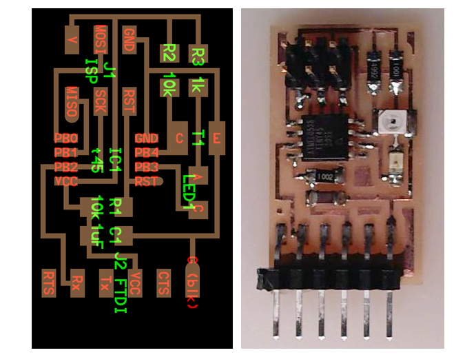
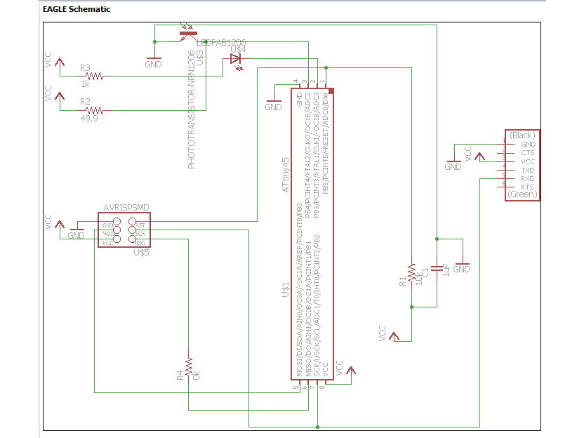
I redrew the original board in Eagle (see Light section on this webpage). I added a zero ohm resistor (R4) to the board because I did not manage to have 4 copper lines under the ATtiny45 like they were in the original board design.
3
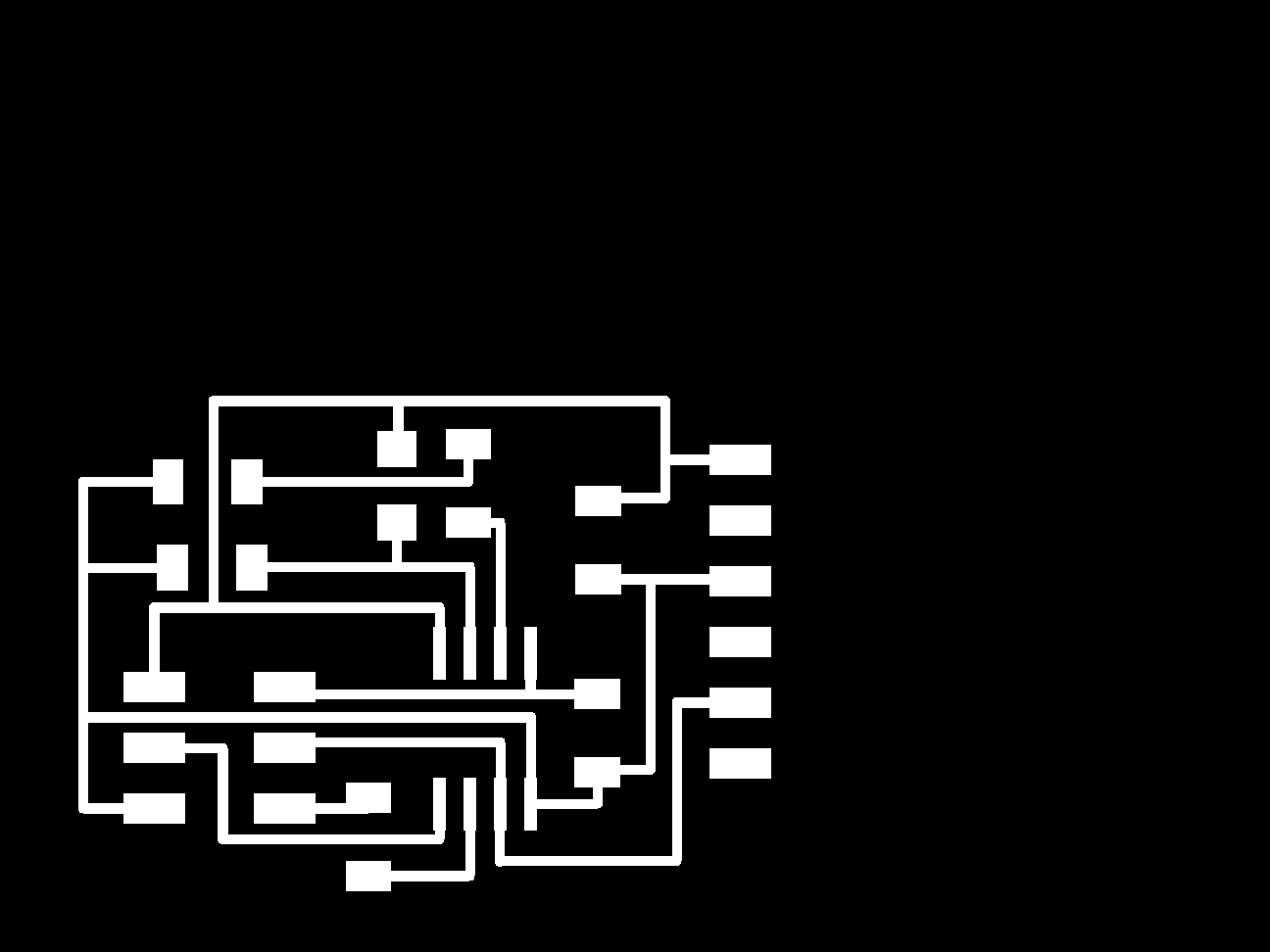
After arranging all components in Eagle's Board mode I exported the result in .png format to be sent to the Modela MSX-20 milling machine. I did not manage to get rid of the large black area around my board. This was not a real problem since the machine only mills the white parts, but I have to figure out later how to fix this.
4
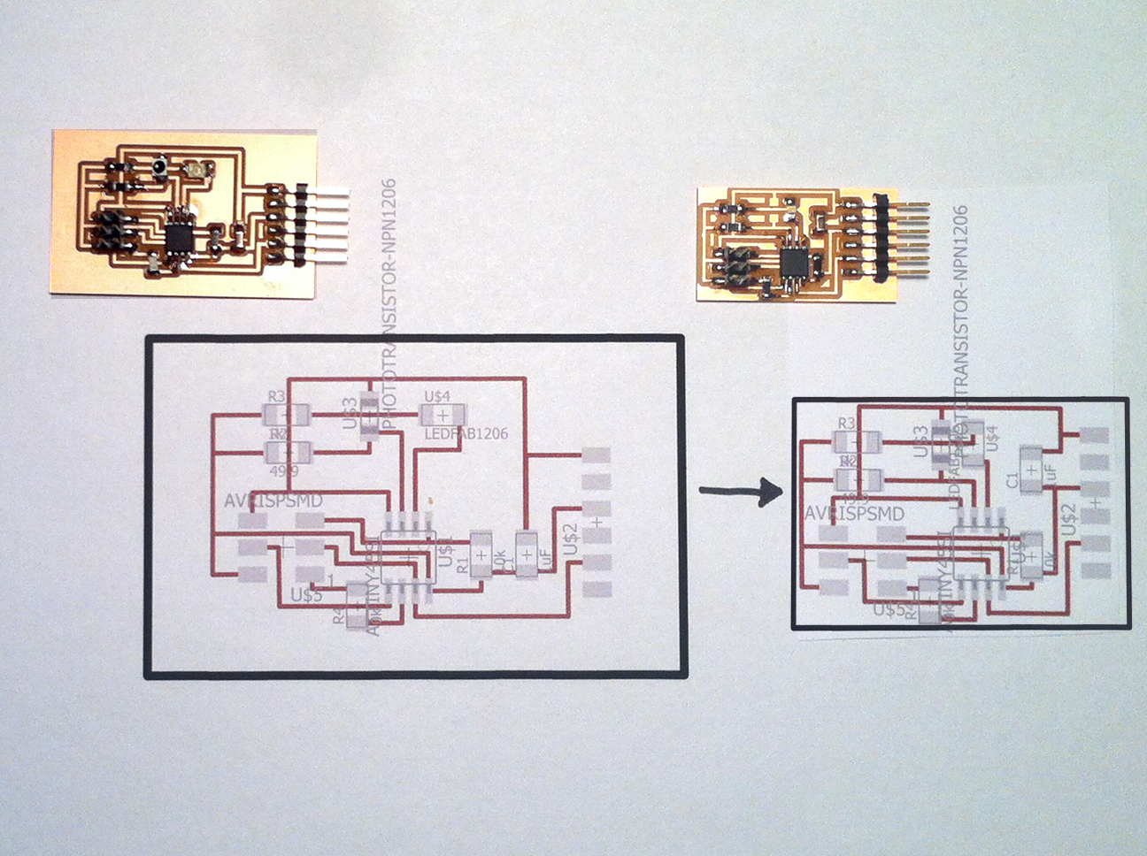
After having soldered all components to the board, I made a smaller version by rearranging the components in Eagle's Board mode. Unfortunately later in the process this smaller board appeared to have a problem: an error 1 message and an advise to check the connections. I checked all connections, but couldn't find what was wrong. For the next steps I decided to go back to the bigger board I made first.
5
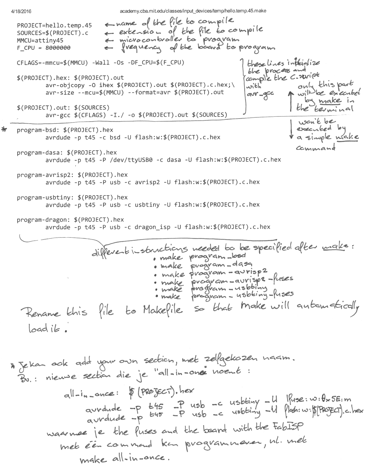
When it came to programming the board, I didn't remember quite well anymore how to do it. Fortunately one of my class mates reminded me of this document in which it is clearly explained.
6
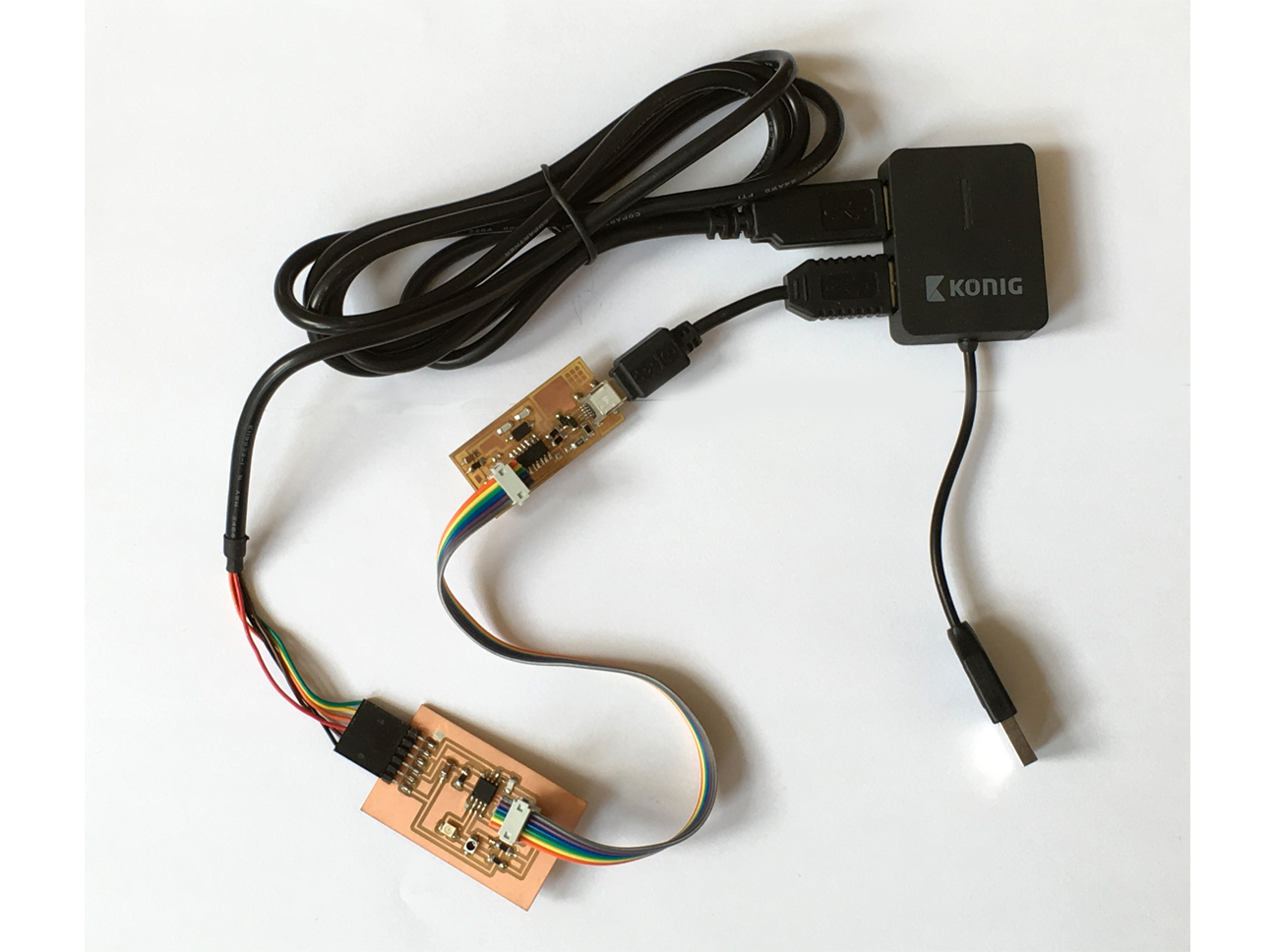
Due to the limited amount of USB ports on my laptop I needed a USB hub to properly connect the programmer and Synchronous Detection Board to my machine.
7
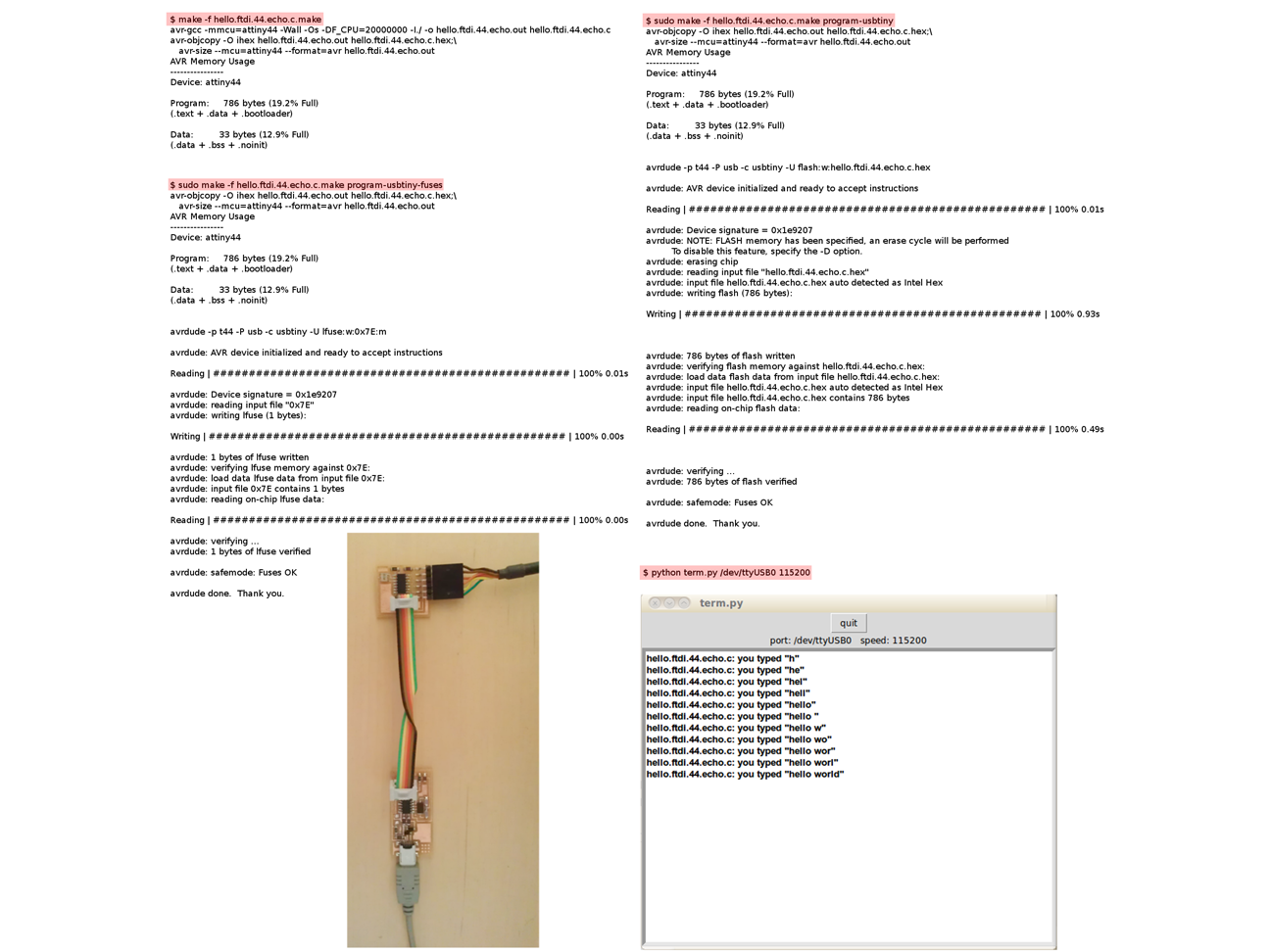
I took a better look at the make commands in the document to find out why commands like "make program-usbtiny" are needed and I added these notes to the instructions for clarity.
8
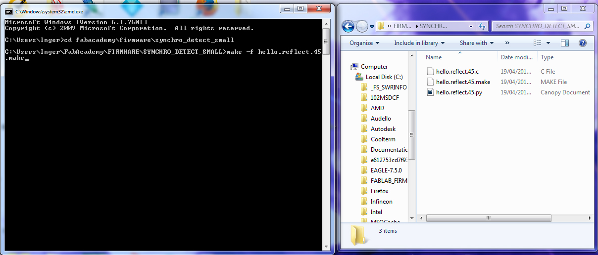
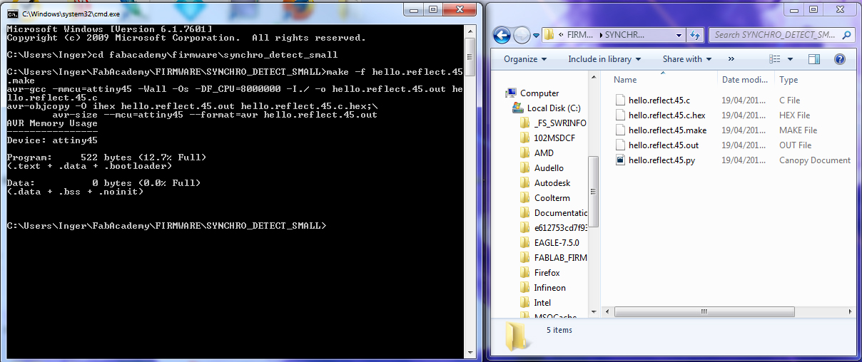
I copied the hello.reflect.45.make file and the .c and .py file to the right directory. In the command line I then typed make -f hello.reflect.45.make as per the make instructions and hit return.
9
By doing so both a hex and out file were created. Since there was no program-usbtiny-fuses file, the second step in the instruction could be skipped. After having executed the command make -f hello.reflect.45.c.make program-usbtiny, the Synchronous Detection board was ready for use.
10
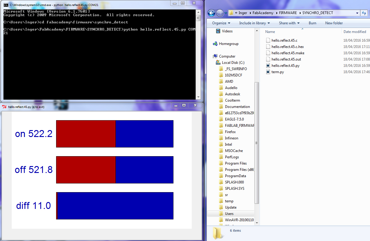
It took a while to figure out how to use it (trial and error and trying to understand what the error messages meant), but then it worked: in the command line I typed python hello.reflect.45.py COM21 and that was it! (Before this and in order to make sure the baud rate was 115200 I downloaded term.py and in cmd typed python term.py COM21 115200. I am not sure you really have to do this though).
11
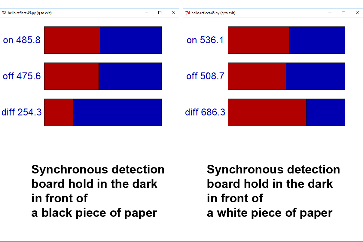
By holding a black or white piece of paper in front of the IR LED, I could see the difference between the phototransistor detecting (almost) no reflected IR light versus detecting a lot. For my final project I plan to use this sensor data as input for changing the colors of a set of RGB LEDs. UPDATE: because of to be expected latencies in reaction speed, I later decided to use the HALL effect for detection of spinning speed in my final project.
FILES: All files of this week can be found here.
