
1
Because this week's assignment was about composites and not about 3D design as such, I kept the mould very simple. In Fusion 360 I drew a circle, extruded the circle and applied a fillet. I added a box, needed later in the process for the bleeder and breather to hold on (see step 38).

2
I wanted to lasercut the fabric for the composite, so I sketched a design for this too. It must be possible to have a direct Fusion 360 - Lasercutter workflow, but for this Composites assignment I decided not to spend time on figuring out how to do this. Instead I exported the sketch as a .pdf file for further processing in Inkscape.

3
What I definitely wanted to realize though was the direct Fusion 360-Shopbot workflow. For this I switched to Fusion 360's CAM environment to setup the model for manufacturing. First I made the general setup, including setting stock size, stock point and model point.

4
After this, separate setups were made for each toolpath. For each toolpath setup there are 5 tabs to go through, the first one being Tool where all tool information has to be filled in and is calculated.

5
What I really like about Fusion 360 is the way numeric information is visualized, like in this case the Clearance, Retract, Top and Bottom heights in the third setup tab.

6
The same for toolpaths. Once a toolpath's setup is completed the toolpath can be inspected visually and corrected if needed. For the first pass I choose Adaptive Clearing, "a roughing strategy for clearing large quantities effectively".
.png)
7
Then I read about Parallel Finish and I decided to add two Parallel Finish toolpaths to get a smoother finish ....

8
.... one in parallel with the model's X-axis ...

9
... and a second one in parallel with the model's Y-axis.

10
A 4th toolpath was needed to cut out the model from the stock. Although the stock height was 10 cm, I gave this toolpath a depth of only 7 centimeters to avoid practical problems later due to the maximum depth our Shopbot can cut. To remove the mould from the stock I would have to cut the remaining centimeters by hand.

11
In a direct Fusion 360 to ShopBot workflow the last step to do in Fusion is to post process the toolpaths and generate the ShopBot .sbp file by selecting ShopBot OpenSBP in the Post Configuration settings, then give the program a number and save it.

12
Because I check marked the option "Open NC file in editor" when saving the program in Fusion 360, the file automatically opened in ShopBot Edit. Here I could see the ShopBot had to execute 62940 lines to make the model.

13
I opened the Fusion 360 generated .sbp file in the Control Software of the Shopbot and it loaded without any problem. This was the last step in the direct Fusion 360 - ShopBot workflow I intended to setup in our FabLab.

14
Next step to do was to fix styrofoam stock to the spoil board using double sided tape and wooden spacers for additional stability. (Not my arms! I got help from a friendly carpenter.)

15
As in Week 7, from here I followed the steps in this Icelandic Öryggireglur, including the Spindle Warm up Routine to warm up the spindle from 9000 to 12000 RPM. Before starting the cutting job one additional test was done to check on the critical 70mm cutting depth.

16
Once the warming up procedure was finished, the cut job was started and from there all I had to do was watching the ShopBot execute all 62940 instructions lines in the program.

17
Since the first pass was about "clearing large quantities effectively" there were also large quantities of styrofoam parts flying around and filling the model. I tried to reduce the mess by constantly vacuum cleaning out as much material as possible, hence keeping the cutting paths relatively open.

18
This was the result after the Adaptive Clearing path was done. To make this rough-edged surface smoother two additional passes were yet to come.
.png)
19
Although these additional Parallel Finish passes added a considerable amount of time to the manufacturing of the mould, the surface of the mould become so much smoother that it definitely was worth to add these passes.

20
As said before the foam thickness (10 cm) was too high for the spindle, which was not a problem because for my 7cm high model I did not need to cut to full depth. However, to release the model from the stock a last toolpath was needed, being me cutting with a knife to full depth by hand.

21
The final result: a smooth-surfaced mould, manufactured in a direct Fusion 360-ShopBot workflow.

22
Next step was to cut the fabric. I imported the circle .dxf file in Inkscape to adjust line color and thickness and saved the file in .pdf format. The .pdf file was opened in Acrobat to be send in the next step as a cutting job to the laser cutter.

23
I did some small tests in the corner of the fabric (a thin, woven polyester textile) and used what seemed to be the best settings to cut full circles. Unfortunately with these settings (vector 50%, power 80%, freq.500; see test sheet) all seemed fine, but ....

24
... while the cutting was still going on,the fabric was blown away by the lasercutter's fan and the cutting job could not be finished!

25
To try and solve this the fabric was taped to the borders of the grid and a new cutting job was started.

26
This time the fabric stayed in place and the cutting job could be finished. The procedure was repeated several times to get enough circles. To speed up the process, a few layers of fabric were put on top of each other to be cut at once.

27
This appeared to work even better: because the double and triple layered polyester was heavier and hence could be laid out flatter on the grid, the cut lines were crispier and cleaner.

28
Once the foam mould and fabric circles were ready, it was time to make the composite model itself. This checklist was used (based on the one a co-student made before) to gather everything needed ....

29
... including this rather scary item, referred to as a Piercing Tool ...

30
... to be used to pierce a sheet of cling film placed on top of a sheet of loft batting (the loft batting itself later to be used as breather).

31
A second sheet of cling film was used to cover the mould to prevent the composite from sticking to the mould.

32
The basic idea of a composite is to combine the strength in tension of fibers (in my case: a thin polyesther fabric) with a resin, being strong in compression. The resin (SUPER SAP® CLR SYSTEM) consisted of an epoxy and hardener to be mixed in a 100:47 weight ratio.
33
The resin mixture was poured on the fabric and spread with the spreaders .....

34
... and the tramped fabric was put on the mould. Because the fabric was so thin it was difficult to position it.

35
I decided to use more resin per layer and this worked better: the tramped fabric stayed better in place when positioned on the mould.

36
When done with putting all layers on the mould (each layer in a different direction than the previous one and taking care to well cover the sides too), the pierced cling film (aka the bleeder) was put on top of the mould.

37
The breather (loft batting) was put on top of the cling film.

38
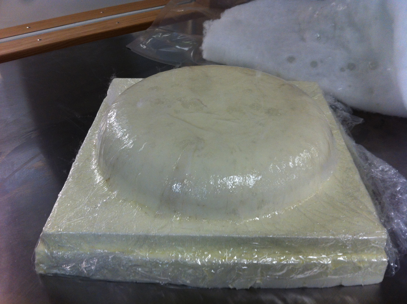
Everything was put in a vacuum bag and pressure on the mould was created by sucking the air out, using a vacuum cleaner. Because after a while the vacuum bag became less stiff due to small amounts of air escaping through the valve, a second vacuum bag was used to solve the problem.

39
Twelve hours later the model was taken out of the bags.
40
I removed the breather and the bleeder.

41
After this I took the composite model from the mould. The cling film really helped to smoothly release the composite model from the mould, but ....

42
... it was very hard to remove the cling film itself from the model: the thin polyesther fabric had wrinkled, folding in the thin plastic sheet. I teared off the excess cling film from the borders, looked at the model and concluded it had a very special charm: it looked fluffy and fragile while in fact it wass very strong and totally unbreakable. I really like the result of this week's assignment and everything I learned and achieved while getting there!
FILES: All files of this week can be found here.
