1
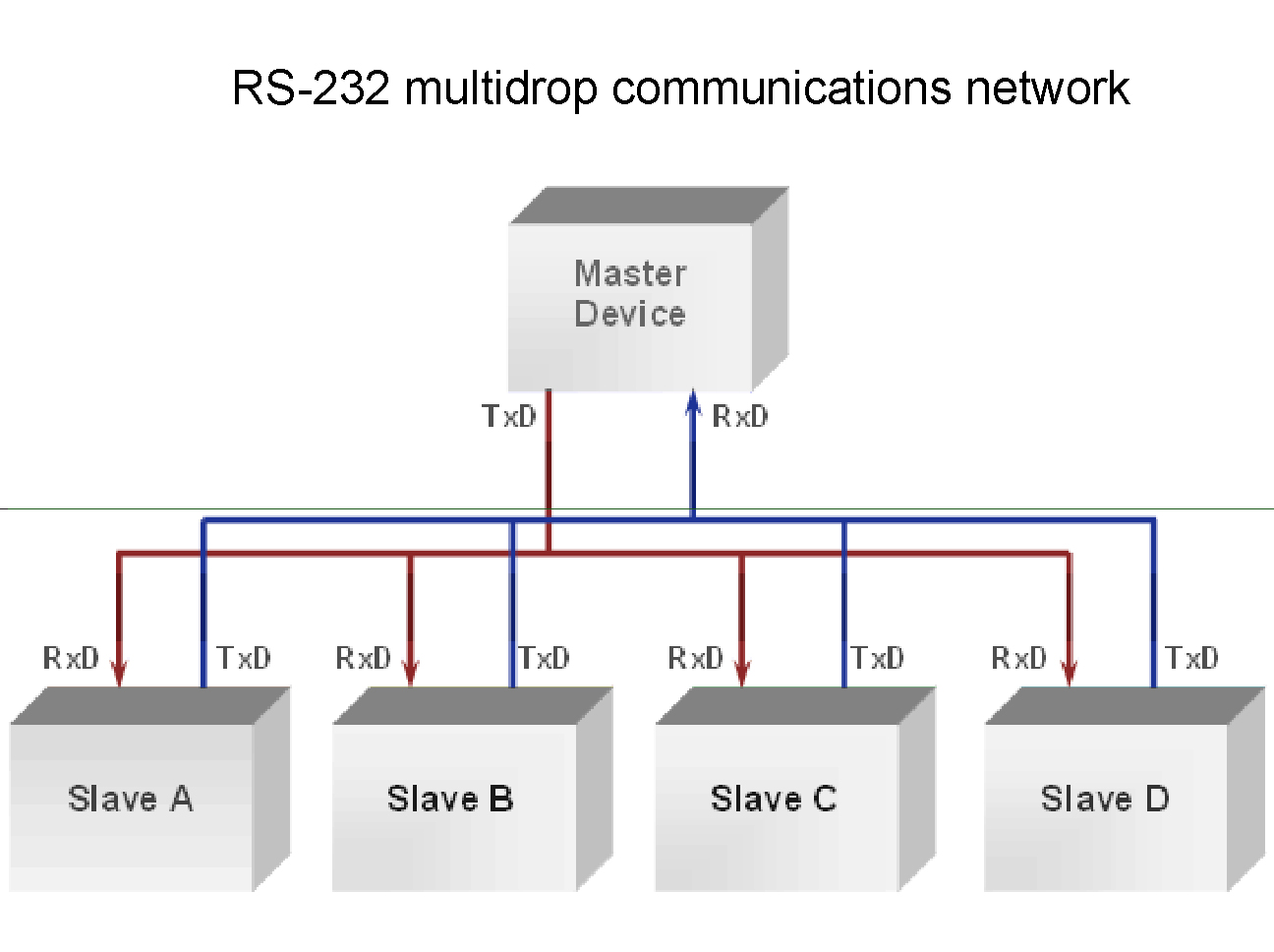
As a 2016 continuing student, for this week's assignment I wanted to document what I already did in 2016, being a simple RS-232 multidrop communications network ....
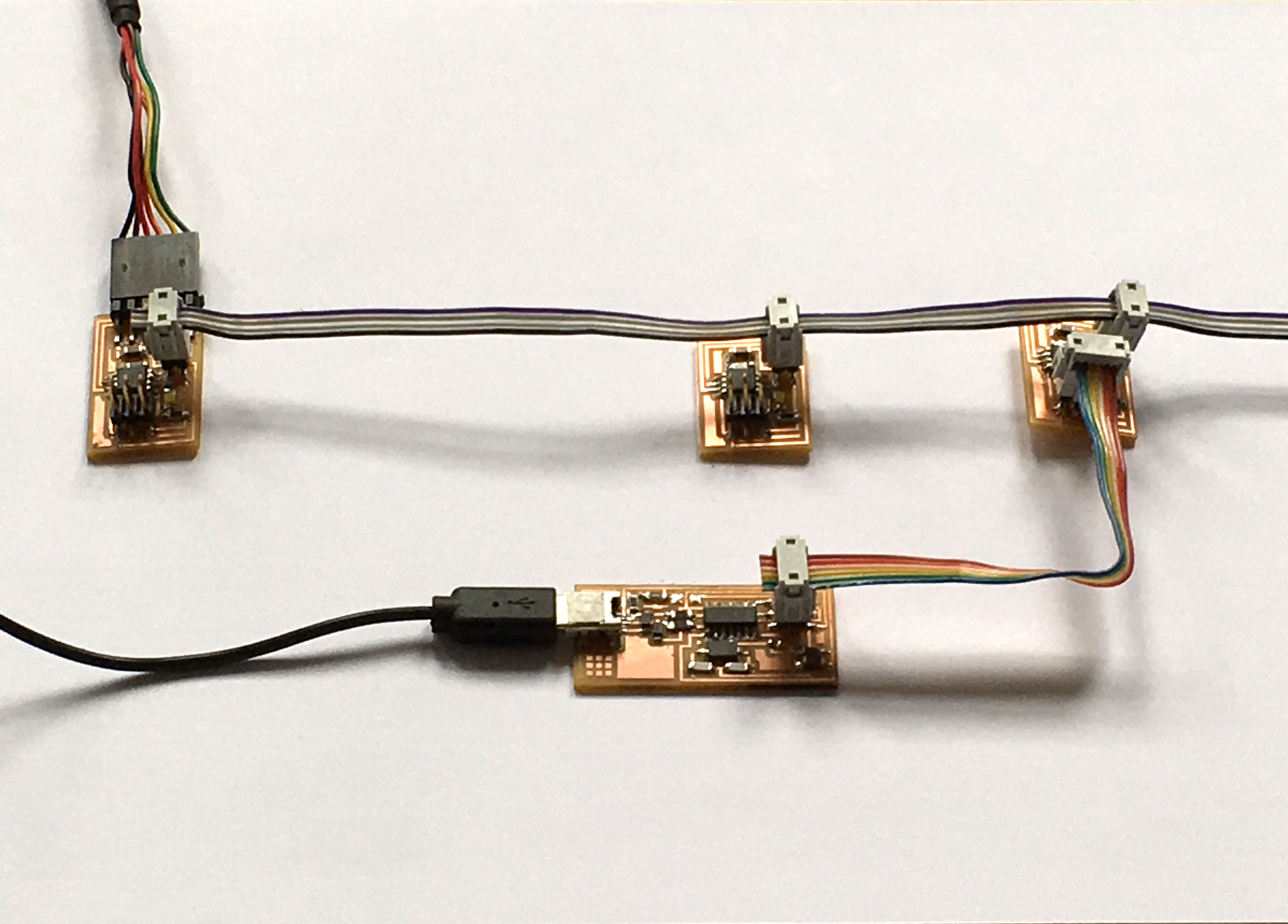
2
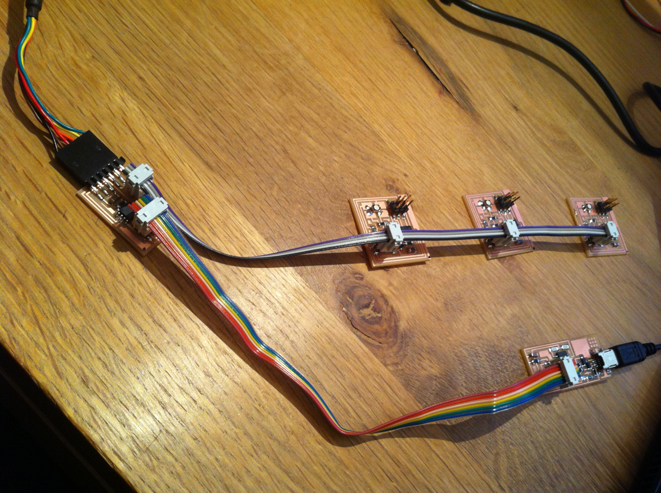
..... consisting of a bridge board and 3 RGB LED node boards. This picture shows the configuration of bridge board plus 3 RGB LED node boards, hooked up to my ISP programmer to be programmed.
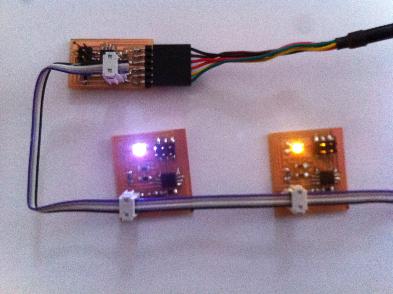
3
The programmed RGB LED node boards faded up one after the other, as per the code I used at that time. Unfortunately I could not find that code anymore and because I also forgot quite a bit about RS-232 and networking, I decided to redo part of the assignment. To refresh my memory I read this tutorial and I watched Neil's 2018 lecture on the subject.
4
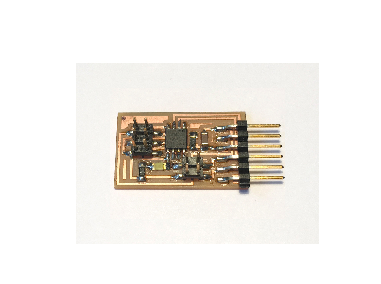
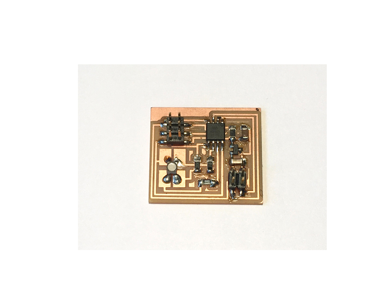
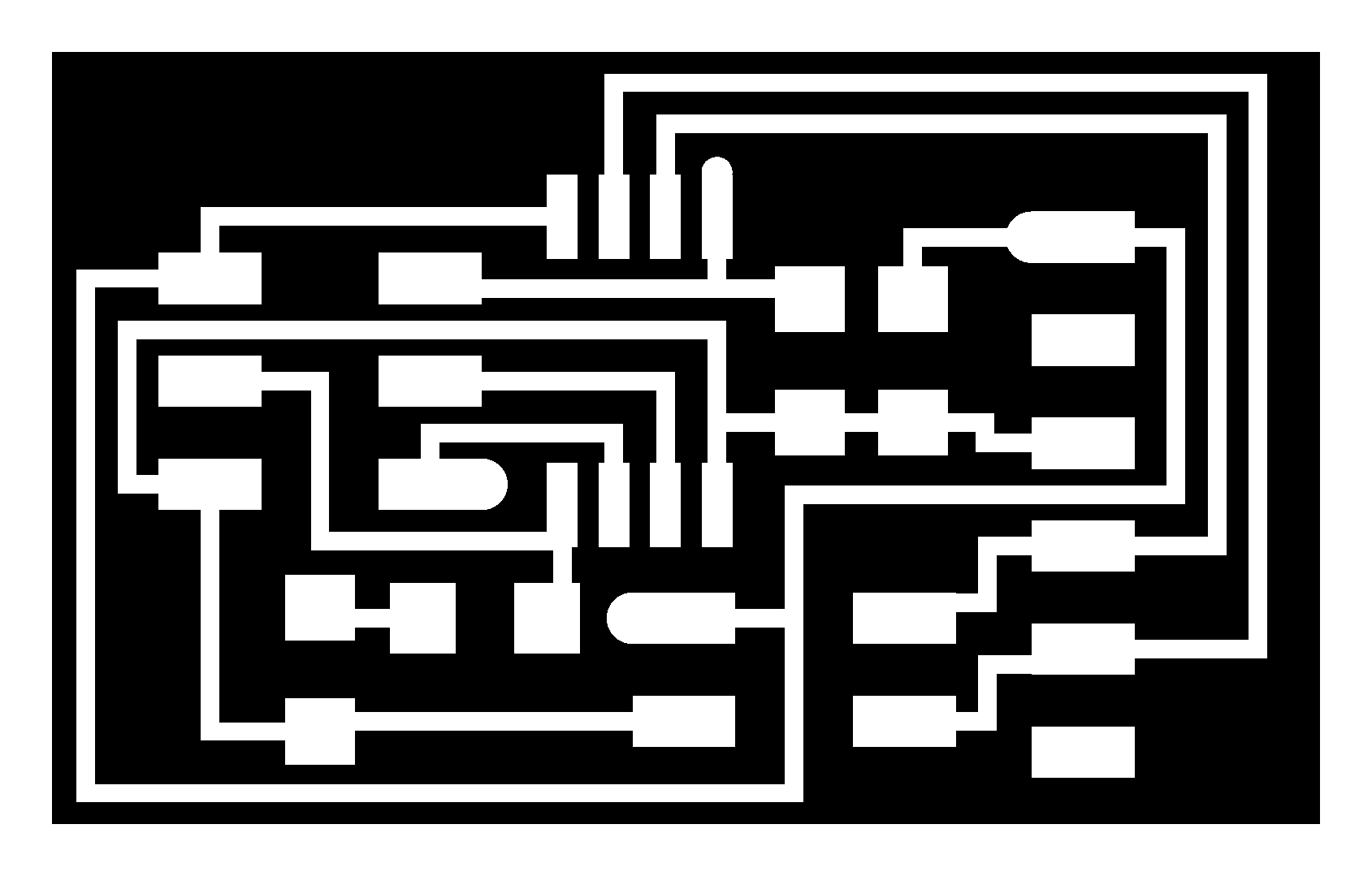
I started by making two node boards as per the tutorial, basically being the bridge board without the FTDI connector. To save time I took the .png files of the traces and outlines (in 2016 I did design both the bridge and the RGB LED nodes in Eagle, so I thought I didn't have to show again I can do that). I milled the boards on my own Modela MDX-15 (why I needed to get one of my own is a whole different story), using the Fab Modules.
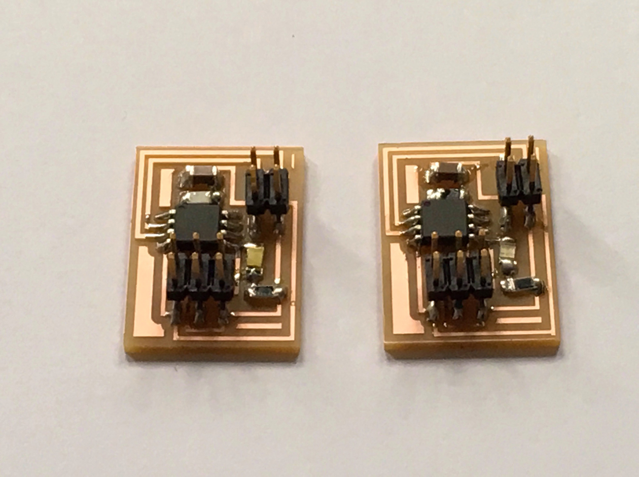
5
The boards came out great and after soldering all components at the right spots the two simple node boards were ready to be programmed as nodes in an RS232 network.
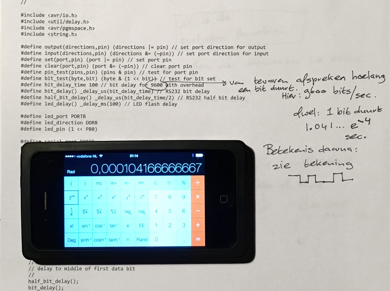
6
For this I first attended the network instructions my local instructor Bas gave for the Nordic Fab Academy group. I have to admit a lot of things were very unclear to me in 2016. For instance: the part about baud rates and bit lengths, needed to be specified because otherwise communication is impossible. Fortunately now I understood all this a lot better!
7
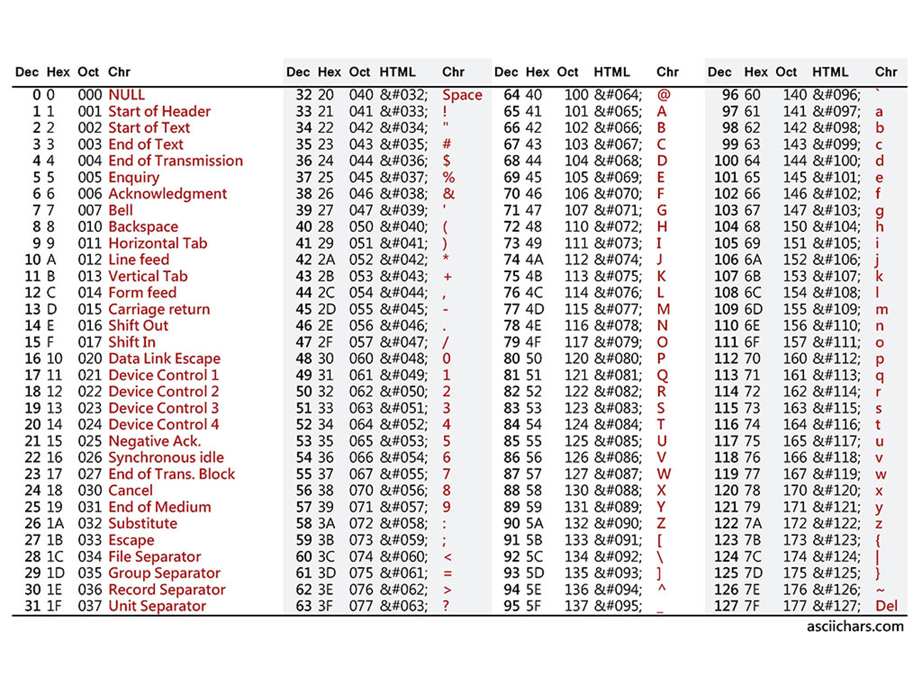
The same was true for the part about how transmission of ASCII characters takes place, for instance: how the letter 'J' is transmitted (decimal numer 74 in the ASCII table). We looked at the hex code for this character (4A) and how this is written in zeros and ones (0100 for the 4, 1010 for the A, so all together: 01001010). We also learned about the prefix 0x, meaning 'we are going to send a hexadecimal".
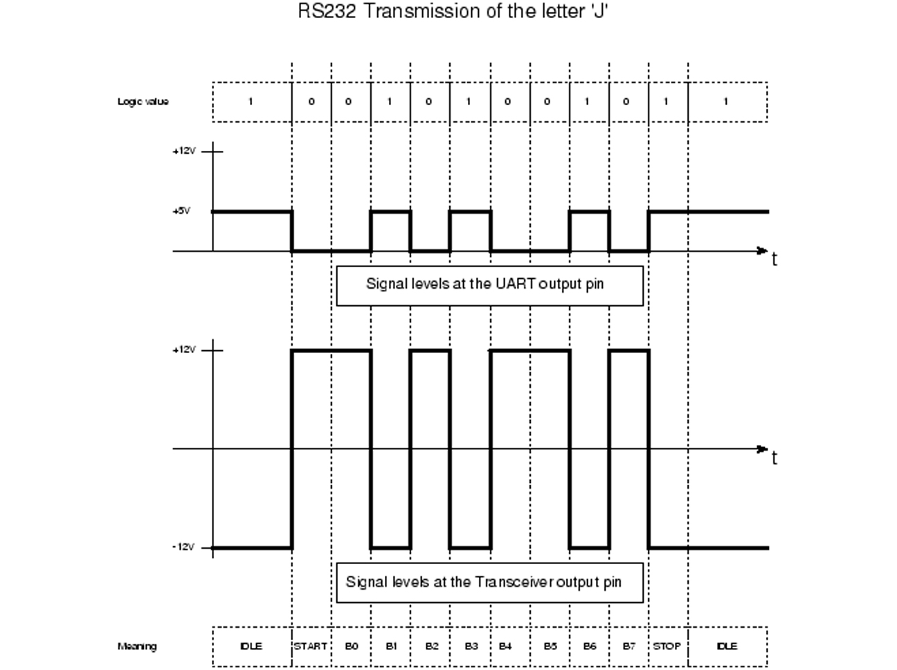
8
Then we looked at the transmission of information at the signal level, again taking the transmission of the letter 'J' as an example. Looking at the bit patterns I now understood that the RS232 protocol just spits out zeros and ones without clock, as opposed to for instance I2C.
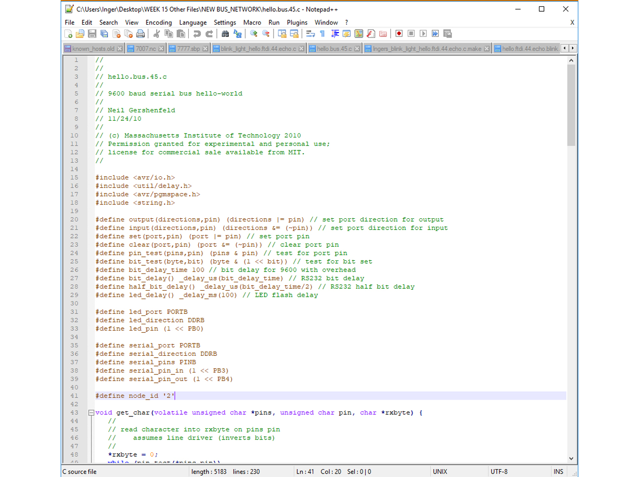
9
Going back to the tutorial, the next step was to change the C code for each node, giving each node an identity number (see line 41 of the code), save the code and flash it to a board. In an RS232 network the node identity is important because nodes can all listen to the master, but can only talk back when the master adresses the node by its numeber, in which case they can return a 0, a 1 or an X, to go back into input mode again right after having responded.
10
To flash the code to a node (the bridge technically speaking being a node too), the ISP programmer was used and a special cable connected all nodes, using the 4pin header on the boards. The FTDI cable was needed to power the boards, since the ISP programmer doesn't do that.
11
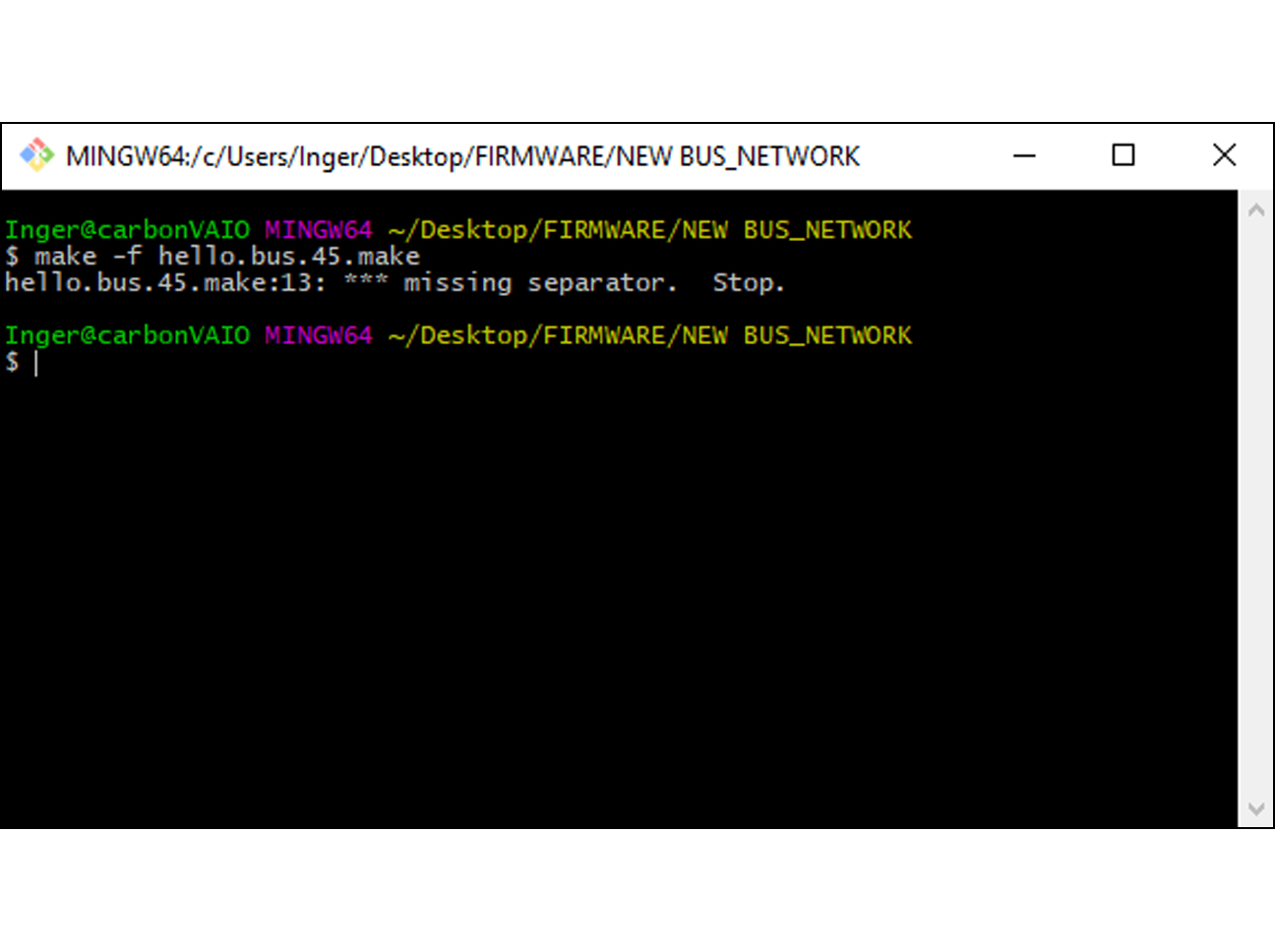
Once all hardware was connected, I tried to program the bridge board to become node number 0. However, when I typed make -f hello.bus.45.make I got a "missing separator" error message. I googled what this meant and found out it meant there were spaces used in the code for indentation instead of tabs, the new version of Make accepting tabs only.
12
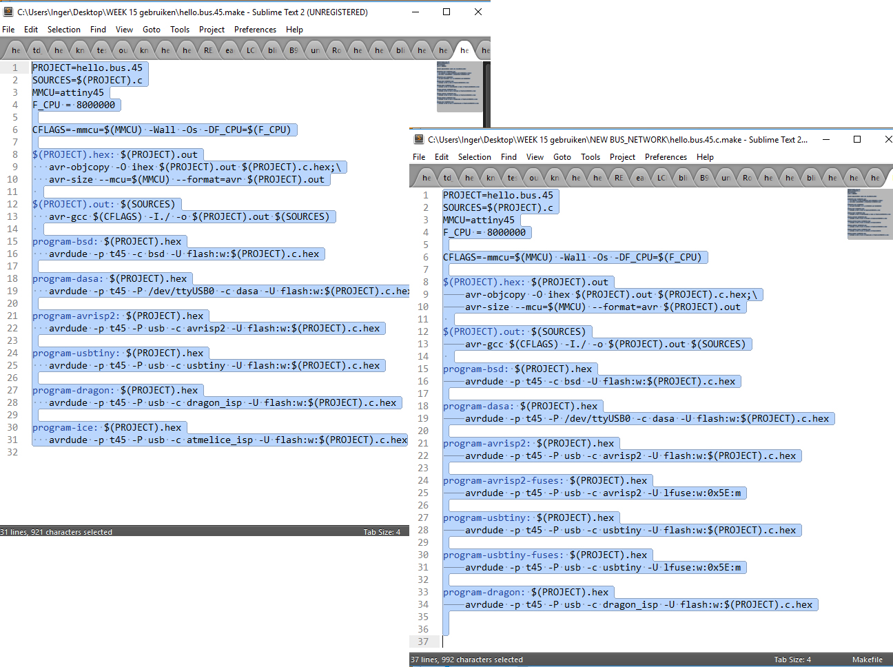
At first I couldn't figure out how to see where the spaces and tabs were, but then I found that when using Sublime Text and selecting text, the spaces and tabs became visible. After replacing all spaces by tabs I saved the make file and hoped for the best.
13
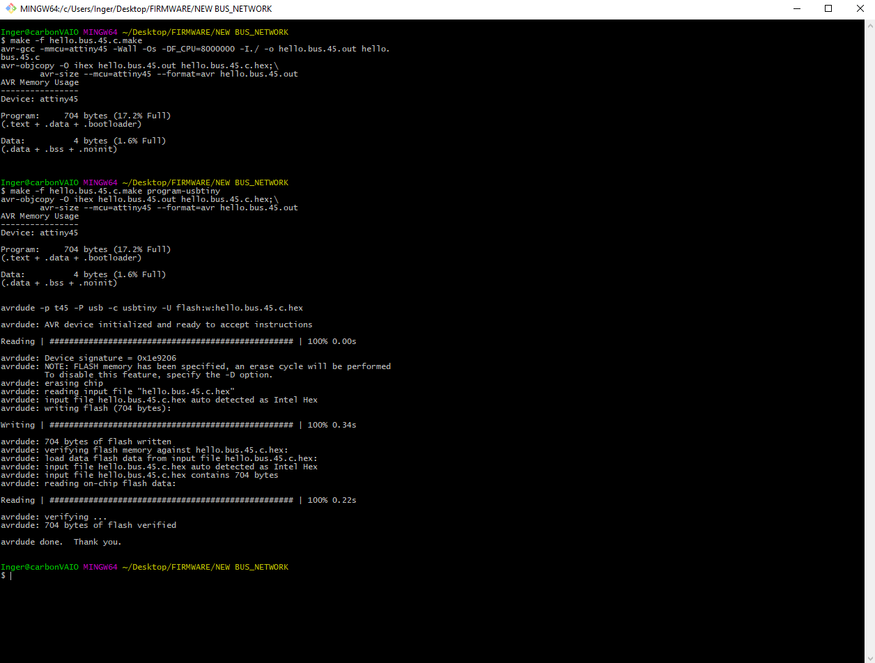
Fortunately this indeed solved the problem and I could continue programming the nodes by changing the identity number, save the C code, flash the code to the board and go to the next number.
14
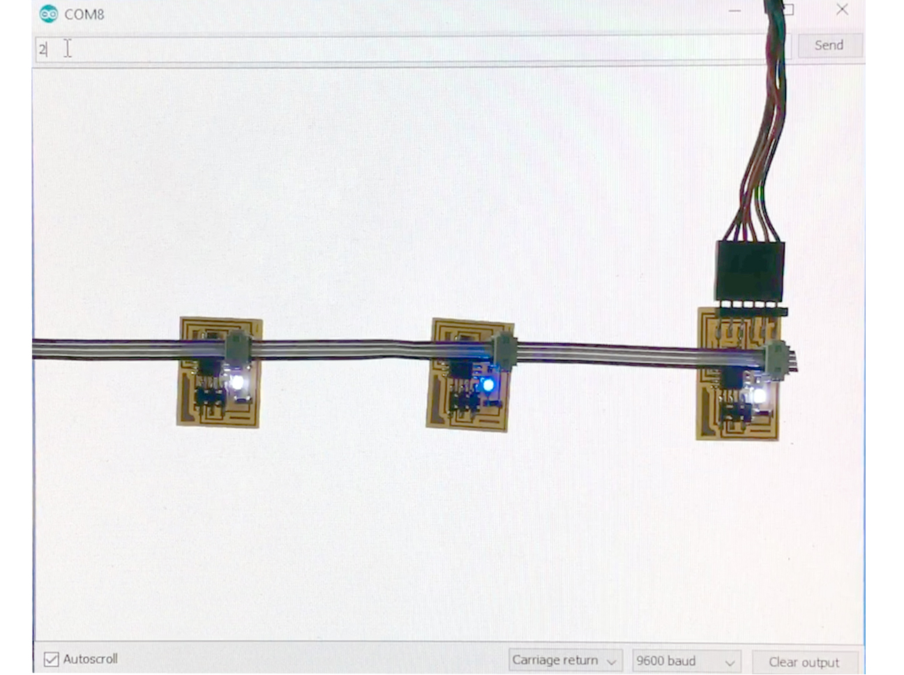
Once done programming the bridge board and the 2 simple node boards, I removed the ISP programmer and opened the Arduino serial monitor. The boards were programmed to all blink once when receiving data, after which only the board that was adressed by its ID number would blink for a second time and the node number would be printed to the screen. I typed 2 and all nodes blinked ....
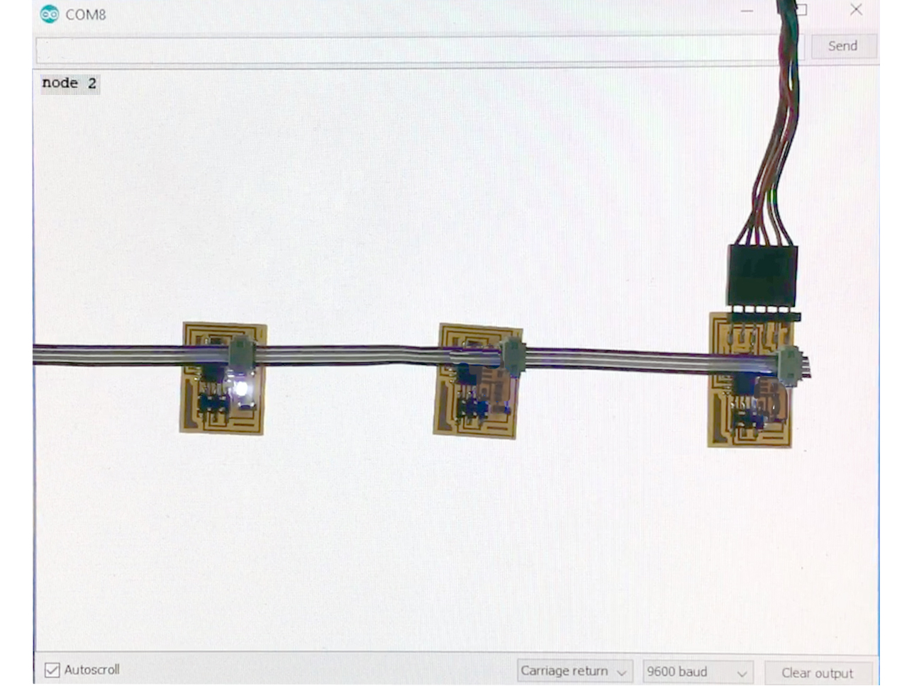
15
... and then node number 2 blinked for a second time while the text 'node 2' appeared on screen: the RS232 network was functioning exactly as it was designed to do.
16
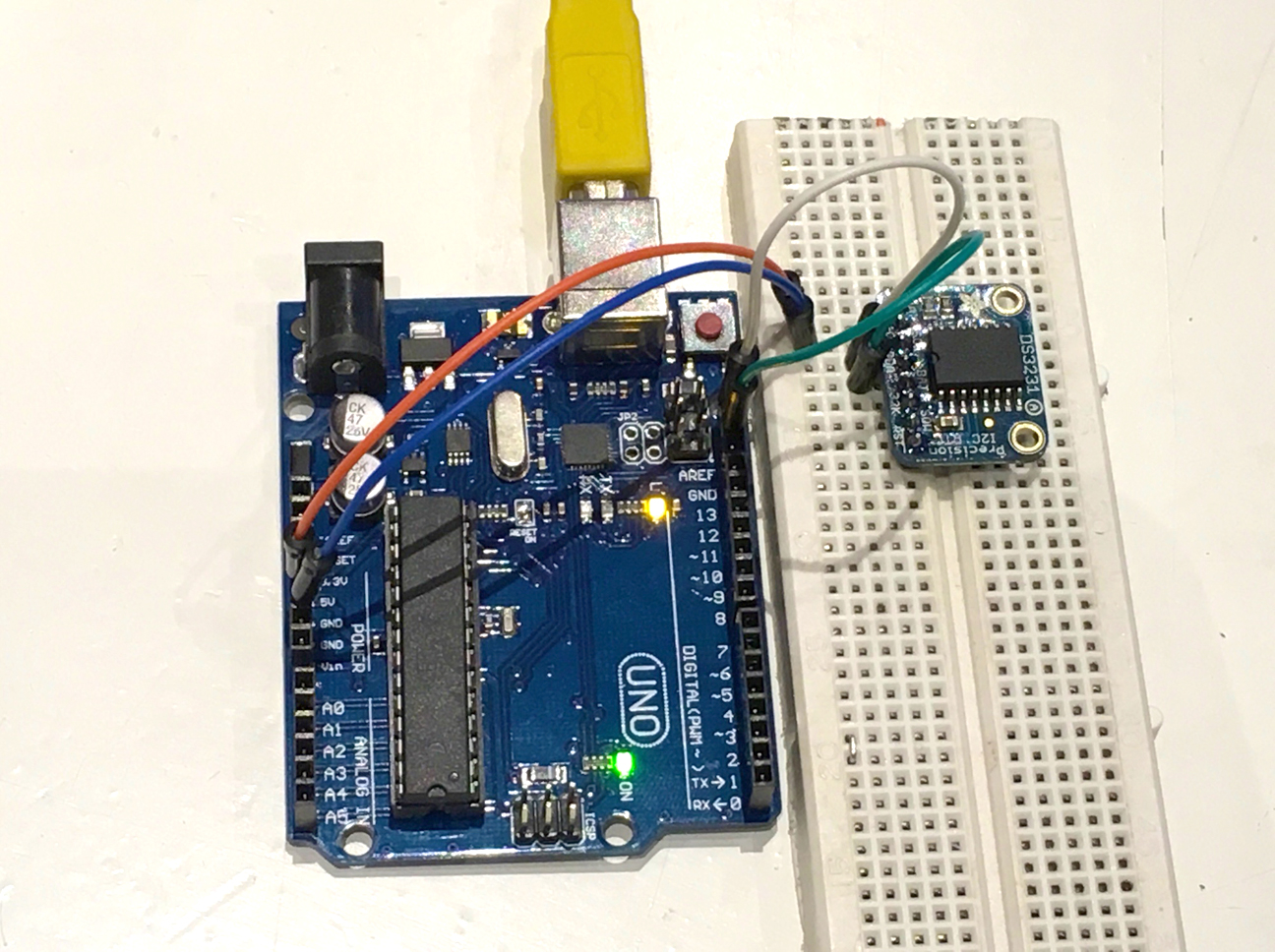
EXTRA: For a project I am working on in the context of Make Health:Prototyping I use a DS3231 RTC, connected to an Arduino via I2C. Goal of the project is to make a wearable, silent time management device for people with acquired brain damage after stroke, that reminds them discretely to take periods of rest during the day.
17
First step is to make an Arduino-based breadboarded rough version with Time from the precision RTC as input and different vibes from a vibration motor as output. Next step will be to make it smaller and wearable by using an ATtiny85 instead of an Arduino.
18
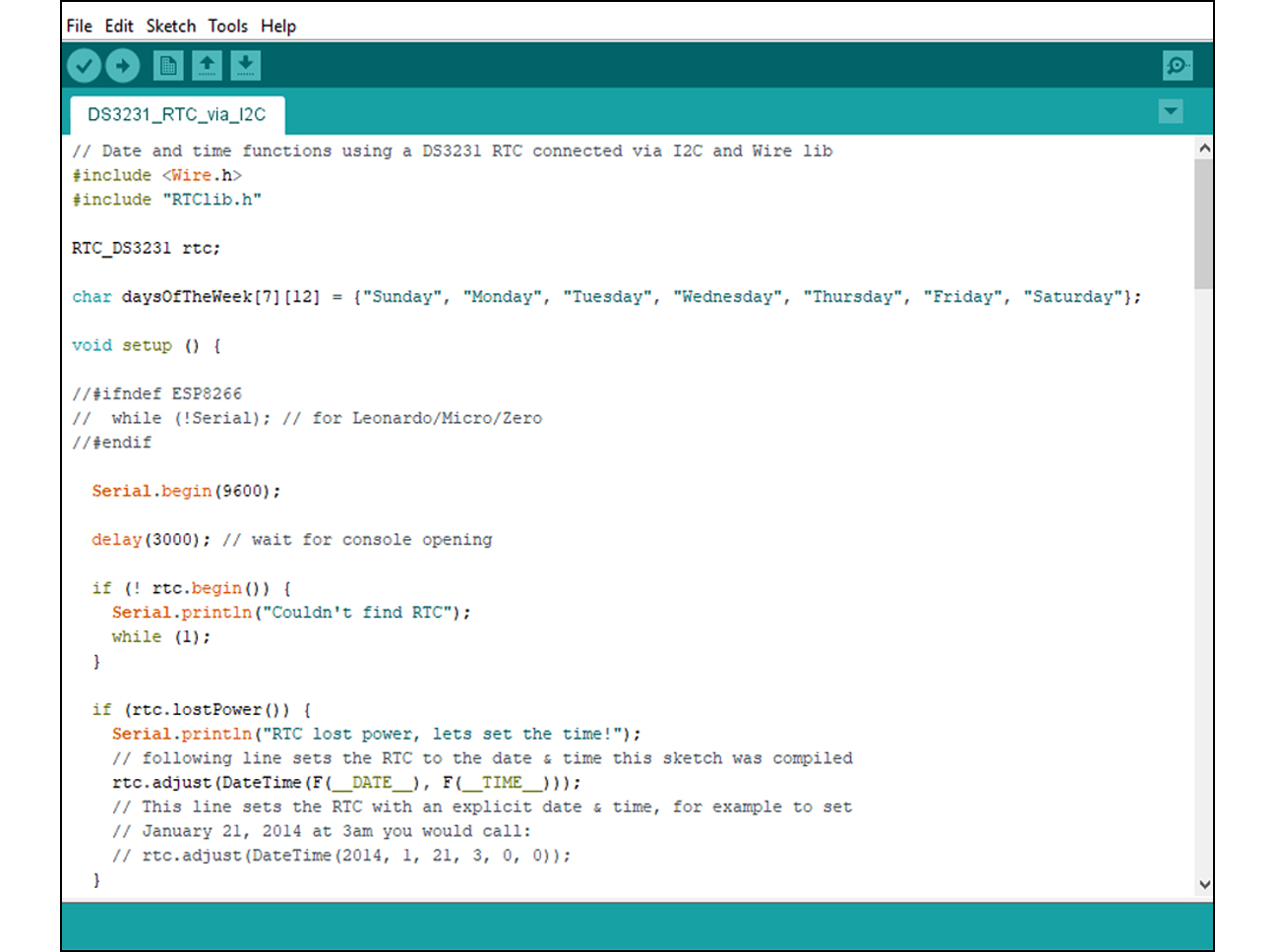
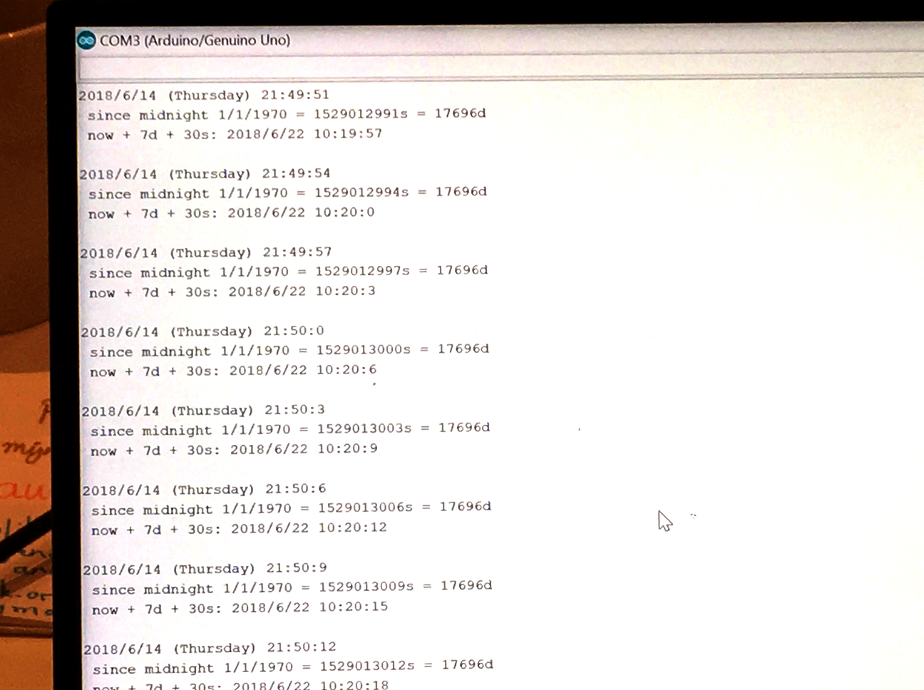
This picture shows that the Arduino sees the RTC module and writes the data to the screen in the Arduino serial monitor, using I2C communication and the Arduino Wire library. Because by using this library everything that makes I2C different from RS232 is "hidden under the hood", it was quite easy for me to use I2C without knowing much about it. I guess this will change a lot when making the step to the ATtiny based version of the wearable.
FILES: All files of this week can be found here.
