Week 3: Computer-Controlled Cutting


Lecture Neil 10/02/2016

Tutorial Bas 12/02/2016 at FabLab Reykjavik

Assignment 1: Design and make a corrugated cardboard press-fit construction kit.


Thumbnail Image 1


1.1

This week the first assignment was to make a corrugated cardboard press-fit construction kit. For this I started designing a fully defined parameterized simple squared shape.

Thumbnail Image 1

1.2

I checked the design by changing the StockThickness parameter. If the design is correct, the width of the slits should change accordingly.

Thumbnail Image 1

1.3

This was indeed the case: changing the StockThickness to 8mm changed the width of the slits too.

Thumbnail Image 1

1.4

Although it should be possible to use the CAM module to lasercut the piece directly from Fusion 360, at FabLab Reykjavik the infrastructure to do this is not set up (yet). I made a separate From Fusion 360 to Laser cutter doc explaining the workflow as it is now, starting with exporting a dxf file from Fusion.
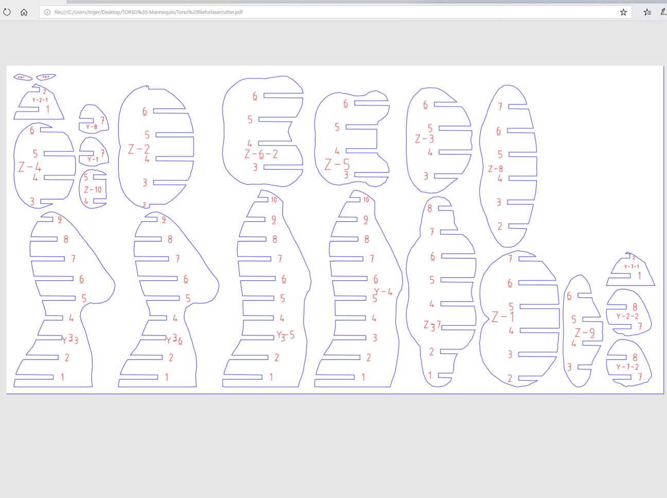
 

Thumbnail Image 1

1.5

In Inkscape this dxf file is used to create the proper lines and line properties for press-fitting. The result is saved as a pdf file, to be used in the next step in Acrobat to tell the lasercutter which lines are to be cut and/ or engraved.

Thumbnail Image 1

1.6

For future use I made an Excel sheet of the information I could find on the wall of the FabLab about which settings to use for what kind of material. These settings are needed in the next step.

Thumbnail Image 1


1.7

Once the pdf file is opened in Acrobat the proper settings have to be put in for the job and then the job can be started at the lasercutter.
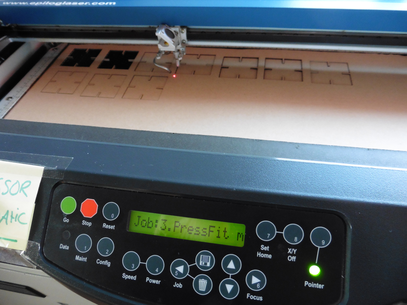
Thumbnail Image 1

1.8

After having tested the workflow with one square, I made a new design with ten squares to be lasercut at once.

Thumbnail Image 11

1.9

Press-fitting these ten squares led to the conclusion that it would be better to "chamfer" the outer corners of the slits, since the corrugated cardboard tended to get damaged very soon when pressed into the sharp-cornered slots.

Thumbnail Image 1

1.10

cham·fer

tr.v. cham·feredcham·fer·ingcham·fers
1. To cut off the edge or corner of; bevel.
2. To cut a groove in; flute.
n.


Thumbnail Image 1

1.11

Fortunately in Fusion 360 when everything is set up properly, chamfering all 160 corners of these 20 squares at once is no problem because it is just a question of changing the value of the CurveSize parameter.

Thumbnail Image 11

1.12

Unfortunately in Inkscape one cannot break apart lines for all 20 squares at the same time, so I ended up doing the procedure for one square and tiled clone the other ones. Nevertheless: voilá, one of the endless possibilities of the resulting press-fit contruction kit.

Thumbnail Image 1

1.13

This schedule visualizes the Fusion 360 - Inkscape - Adobe Acrobat workflow . To get a little bit more experience with it and because it seemed handy to have one, I decided to make a gauge to measure the thickness of material to be cut.

Thumbnail Image 1

1.14

Once I lasercut the initial design, I noticed it would be better to add 2 more slits. Bas (our lab guru) told me not to take out what I already had cut, but to leave everything as it was and add to it.

Thumbnail Image 11

1.15

For this I made a separate design for 2 extra slits.

Thumbnail Image 1

1.16

This GaugeExtraSlits job was sent separately to the laser cutter, to be cut in the gauge that was still in the machine.

Thumbnail Image 1

1.17

To my pride and surprise this worked perfectly!

Thumbnail Image 11

1.18

The result was a gauge including the two extra slits that were not in the original design.

Thumbnail Image 1

1.19

A second improvement included a hole to hang the gauge and several additional slits, to be lasercut both from Timbur and Plexigler, for which I had to change the laser cutter settings.

Thumbnail Image 1

1.20

And this is what happens if you do not change those settings properly: the material burns and melts.

Thumbnail Image 11

1.21

After adjusting the settings this became the final result: two very practical gauges to measure the thickness of material to be cut!

Assignment 2: Design a vinyl cutting project.


Thumbnail Image 1

2.1

For the vinyl cutting assignment I decided to make a Max Verstappen fan T-shirt for my husband, who is a huge fan of the young Dutch Formula-1 driver. On the web I found a .png file of a black MAX logo that I could use to make the silver logo (on a black T-shirt) I had in mind.

Thumbnail Image 1

2.2

In Fusion 360 I used this .png file as a decal on the front face of a box. (I used Fusion 360 because earlier I decided to use it for all vector-based design). I constructed all outer lines of the logo in Model mode and saved the front face of the box as a .dxf file for Inkscape.

Thumbnail Image 11

2.3

I imported the .dxf file in Inkscape to position the drawing correctly on a page and set the line thickness to 0.02 mm. (Later I found out I made a error and typed 0.2 mm.). I saved the logo as a pdf file for Acrobat.


Thumbnail Image 1

2.4

From here I just followed the instructions for the use of the Roland GX-24 vinyl cutter on the FabLab wiki. At point 2 this instruction says: "Choose a color, place the roll on the grey tray on the backside of the machine." Unfortunately I could not follow that instruction because ….

Thumbnail Image 1

2.5

… the silver vinyl at the lab was not the material that could be used for heat transfer on fabric. So I had to get out and buy a sheet of heat transferable silver vinyl that I found here.  

Thumbnail Image 11

2.6

Very important to remember: the glossy side of this vinyl is the back side and the dull side is the front. The vinyl cutter only cuts the top layer, so it is important to put the vinyl correctly in the cutter = glossy side at the bottom.


Thumbnail Image 1

2.7

Also important was this: because I used a full width sheet of material, I had to choose Edge at point 6 of the instructions for letting the machine find only 1 side of the sheet.

Thumbnail Image 1

2.8

All settings done, the cutting job could be started. When the machine was cutting the logo, all seemed to be OK, but ....

Thumbnail Image 11

2.9

… once the cutting was done, the parts not to be transferred to the fabric have to be peeled off. It was at this stage I discovered the double lines made by the vinyl cutter. This was due to the error I made when setting the line thickness in Inkscape (0.2mm instead of 0.02mm).


Thumbnail Image 1

2.10

Fortunately in this case it was not a big problem: I just very carefully had to remove the extra lines of vinyl to get the desired parts of the logo.

Thumbnail Image 1

2.11

Next step was to go to the heat press (basically a big ironing machine with a handle to press down a hot metal plate onto some fabric put on the bottom plate of the machine) and put the black T-shirt in the press.

Thumbnail Image 11

2.12

I set the temperature to 38 degrees Celsius as per the specs of the vinyl that I read on the website of the store where I bought the vinyl.


Thumbnail Image 1

2.13

Once the logo was positioned correctly, the hot plate was pressed a few times downwards (each time for a few seconds) to glue the vinyl to the fabric.

Thumbnail Image 1

2.14

After letting cool down the T-shirt for a while, the transparent glossy top layer carefully could be removed and the Tshirt was ready ….

Thumbnail Image 11

2.15

… to be worn by my happy husband while watching thrilling Formula-1 races!

.


Extra: Lasercut Mannequin


Thumbnail Image 1

Step 1

In the context of Fabricademy Bootcamp Paris 2017 I made a press-fit MDF scale model of a mannequin. Without going into details the end-to-end workflow (that could be used for a full scale version too) is described here in 6 steps., starting with: make a human in Makehuman and save as a mesh.

Thumbnail Image 1

Step 2

Import the mesh in Fusion 360..

Thumbnail Image 11

Step 3

Modify the 3d model in Fusion's Model mode (in this case I only wanted to make the torso) and go to Slicer.


Thumbnail Image 1

Step 4

Use slicer to turn the 3d model into a 2d build plan and save as a pdf file.

Thumbnail Image 1

Step 5

The pdf file contains cut and engrave information, the latter needed for assembling the model. Lasercut and engrave the pdf file as usual.

.  

Thumbnail Image 11

Step 6

Assemble the model as per the Slicer instructions press fitting all parts in the right order in the right place. When done take a step backwards and admire your model. When using a larger lasercutter or a Shopbot this Makehuman - Fusion 360 - Slicer workflow can be used to make full size mannequins.


FILES: All files of this week can be found here.


Thumbnail Image 1