1
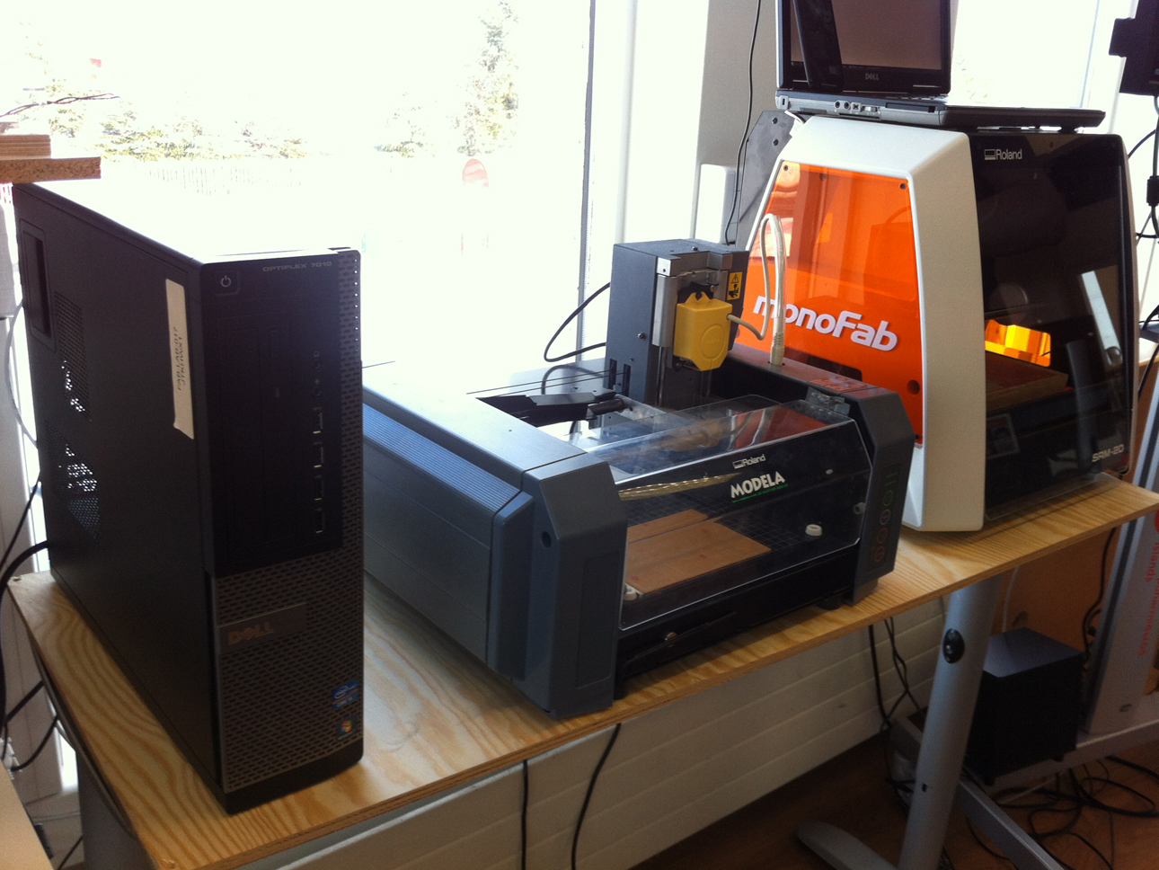
This week we learned to use the Roland Modela and SRM 20 milling machines. After switching on the machines and connecting to the server, first look if the right tool is in it: 1/64 for traces; 1/32 for outline. Switch tool if needed. (Careful: when loosening the screw, support the tip of the tool with a finger at all time in order to not drop the tool!)

2
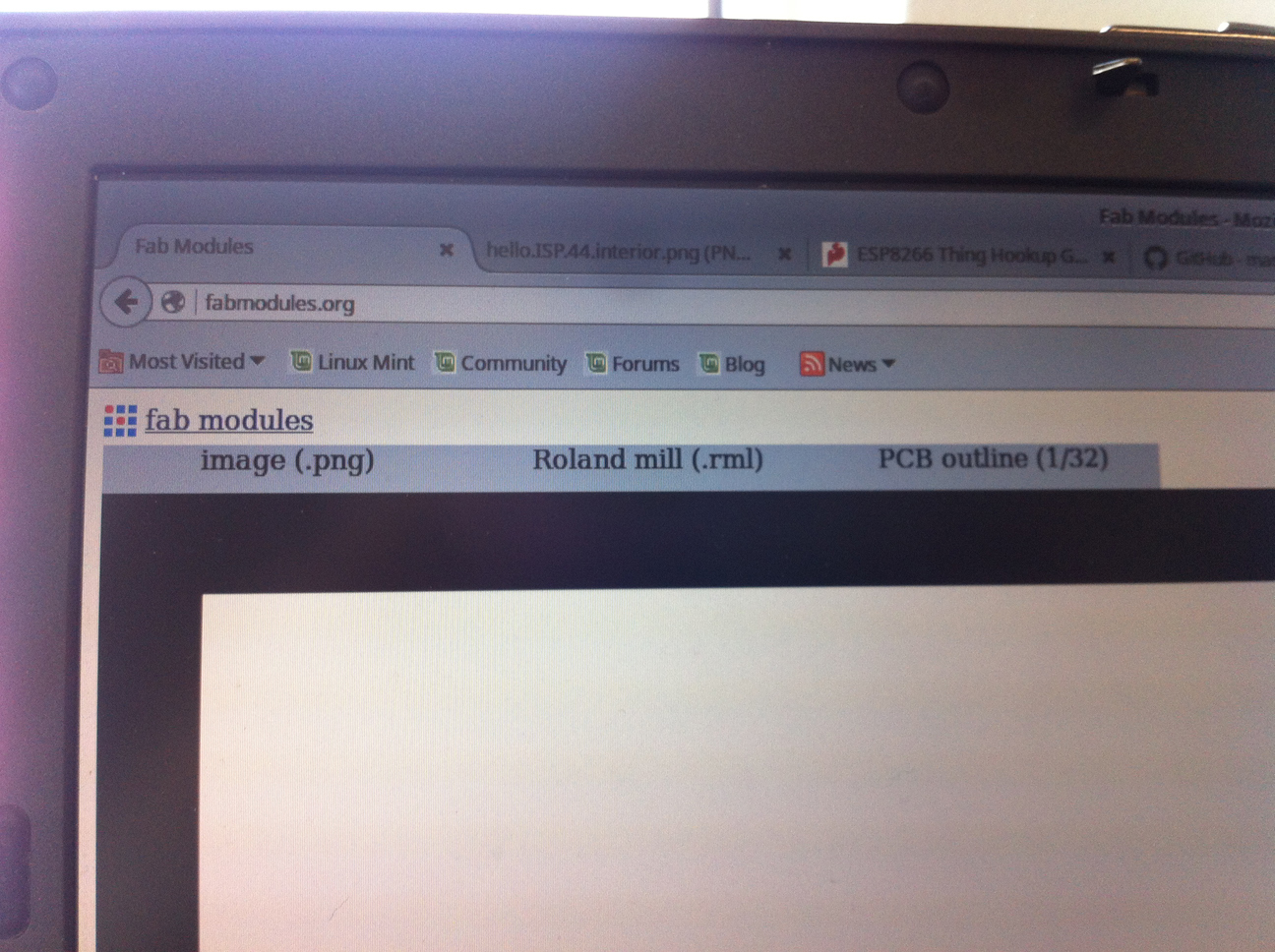
Use the fab modules to select the image, the type of machine and the process (traces or outlines). Do not forget to stick the board to the machine, using the right (= the white) double sided tape. Switch tool if needed.

3
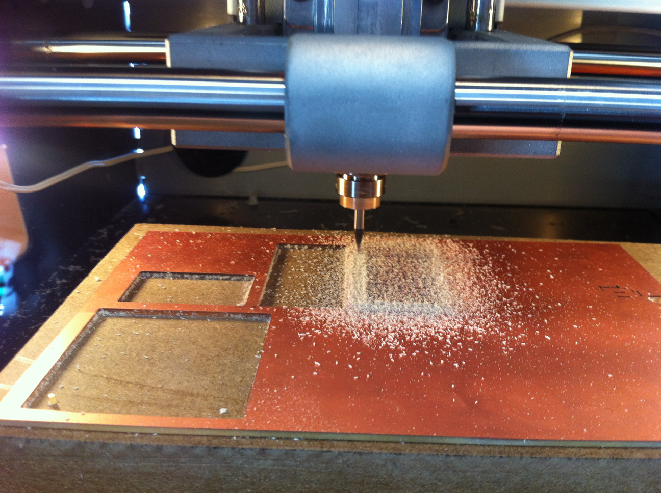
Before starting to mill: move starting point to desired x y coordinates. Then by hand lower the tool to correct z position. Alternatively: use zjog (which is 2mm higher). In the settings change send command to ./mod_print.py/dev/usb/lp0 (so ./ at the beginning and 0 at the end).
4
To cut the board choose PCB outline (1/32) in the fab modules. Change the tool. A dept of 1,7mm is needed to cut the board. When using zjog take into account that the tool is 2mm above the surface of the board.
5
Once the milling is done, remove the debris and use a small screw driver to detach the board from the machine. The PCB is ready for soldering the components onto it now.

6
It is very practical to make a components list including component IDs and values BEFORE starting to solder. I added small pictures of the SMD components, because they look quite different from the normal sized components I am familiair with.
7
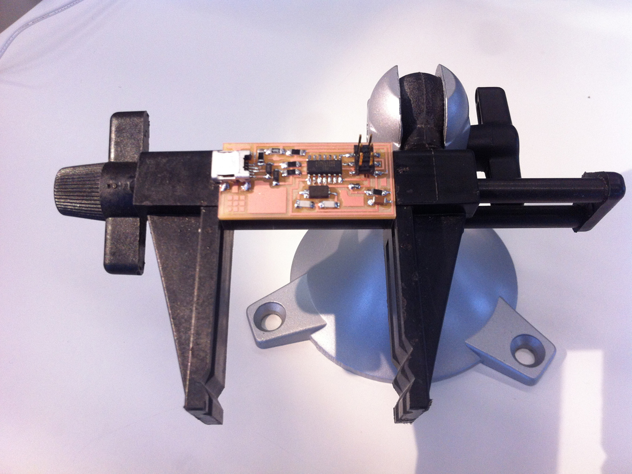
The picture shows how to fixate a tiny board like this in the stand. Also needed: a really strong magnifier, a soldering station that shows the right temperature (300 degrees Celsius) and a nice young class mate to help you out in case you panic because you still cannot see some of the SMD components, let alone their orientation marks!

8
Three versions of the ISP programmer. Soldering done! What follows is the Smoke test. This is really a smoke test: hook the board to your computer and see whether or not smoke is coming out. If you get a message that a USB device is not recognized: that is no smoke and totally to be expected: there is no program in the processor yet!

9
To program the programmer it is necessary to hook both the board to be programmed AND the board that is used to program it to an USB port. Since my VAIO has not enough USB ports to do this, I had to borrow a USB port duplicator. I should have one with me all the time!

10
It is important when making this cable to have the "keys" of the connectors at both ends of the cable in the right direction (which initially I had not).

11
I had some advantages still having a Windows 7 Pro machine: no fixes or patches were needed. All I had to do was follow there FabISP Programming instructions.

12
By just following the instructions line by line without any problem I reached the Wooo! Success! stage at the end of the procedure.
13
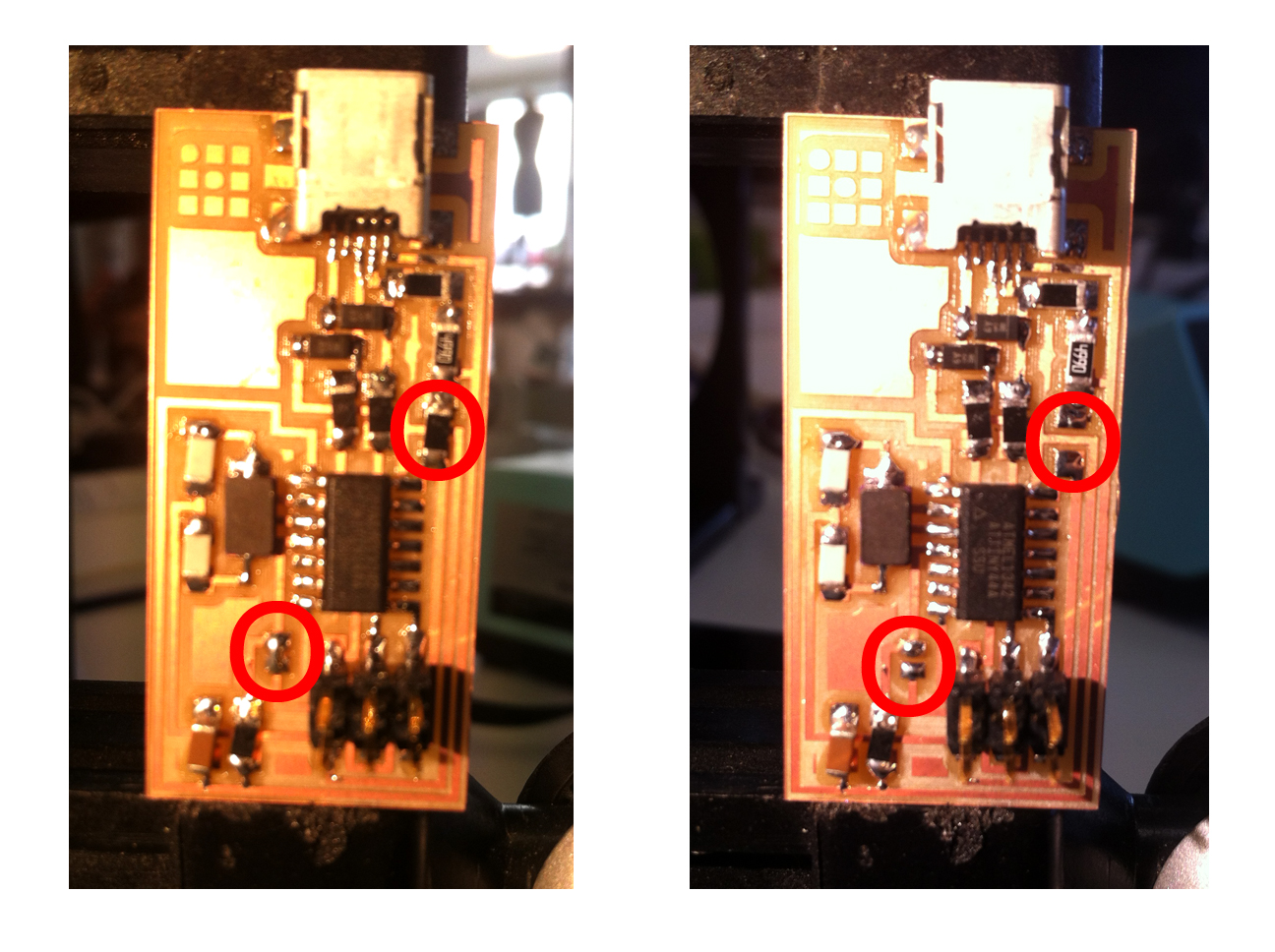
After the programming of the programmer is done: do not forget to remove the 2 jumpers (see red circles on pictures). Otherwise the new made programmer cannot be used to program!
