1.1
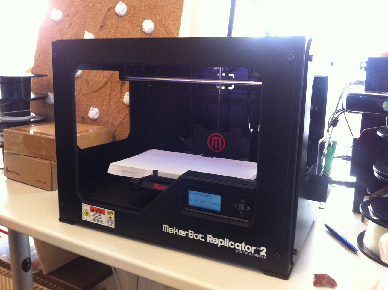
We started the 3D printing assignment by getting to know the MakerBot Replicator 2 and looking into its working in more detail by cleaning the printer head.
1.2
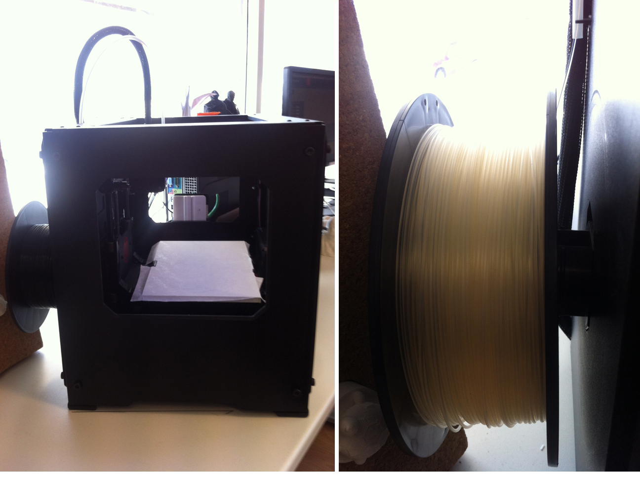
We also learned how to change filament and what kind of filaments are available for this printer. Since for my final project I need to print semi-transparent objects I changed the filament color for the next tests to semi-transparent.
1.3
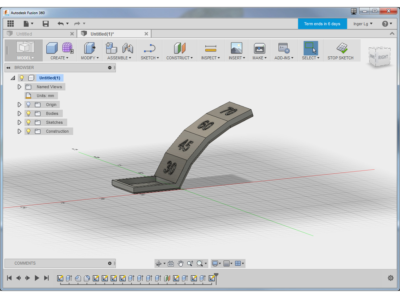
As a group we decided to use Make's 2015 3DP Test Geometries (available via the Thingiverse website) to test our own 3D printers. I made myself/ was responsible for the Overhang Angle test. For me this is an important issue since I have to print bird wings at different angles for my final project. I downloaded the test probes and imported the original Overhang Angle test in Fusion 360. The angles tested in this probe ranged from 30 to 70 degrees, measured from the vertical axis. I exported the file in .stl format.
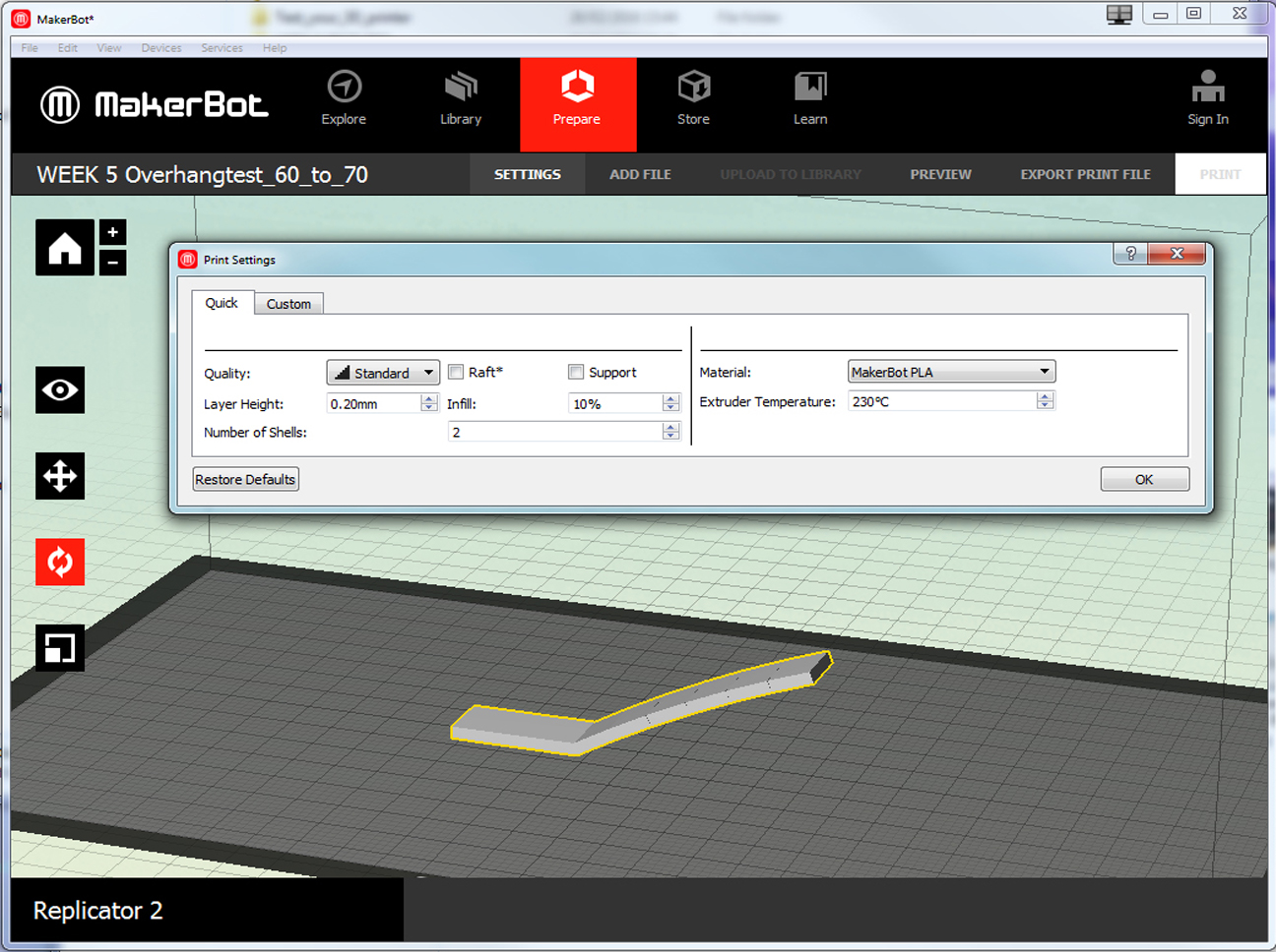
1.4
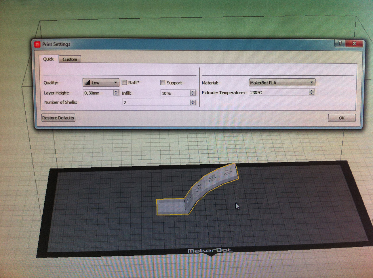
I loaded the .stl file for the overhang test in MakerWare, choose the right device, used the icons on the left side to position the object in the centre and so on, and then in Settings adapted the settings to the material used, being the semi-transparent PLA I choose for this test.
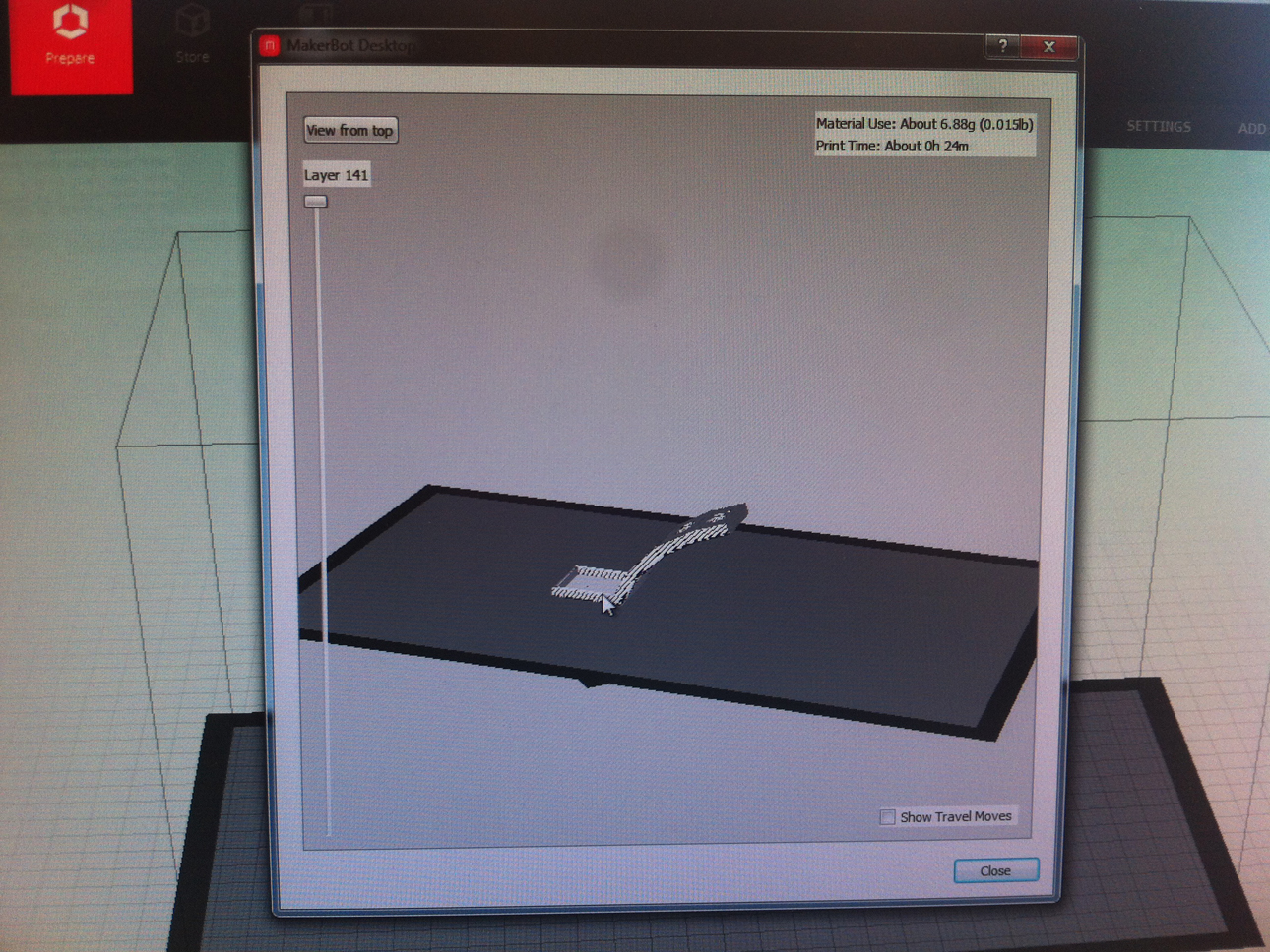
1.5
In Preview it showed that the printing time would be more than 1 hour. So I decided to scale the object to reduce this time. I then saved the print file to the memory card.
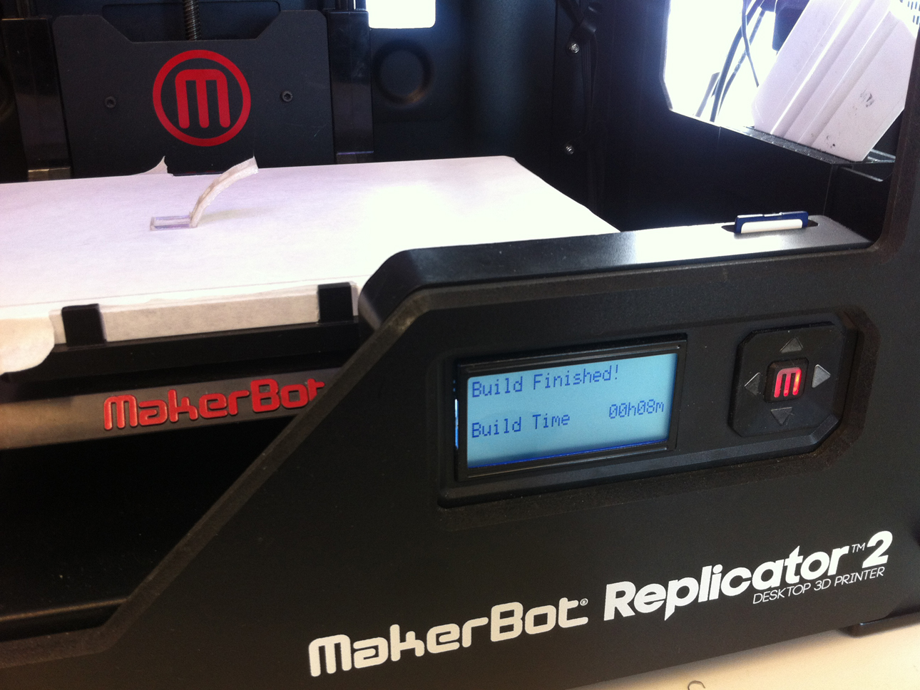
1.6
I put the memory card in the printer's card slot. By using the arrows and M button I choose the right file to be printed and started printing. After 8 minutes the Build was finished. Inspection of the probe showed that somewhere between 60 and 70 degrees the printing became wobly and drippy (see picture 1.9), so I decided to do another test in order to narrow down this test result.
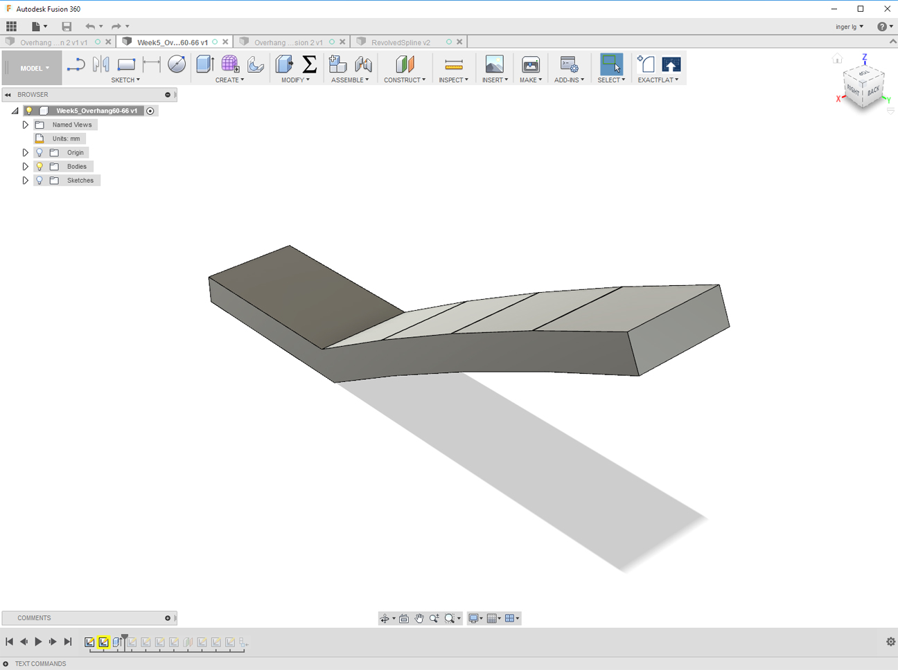
1.7
In Fusion 360 I made a new test probe, using angles of 60 to 70 degrees in increments of 2 degrees. The resulting probe was saved again in .stl format to be further processed in MakerWare.
NOTE: I really liked working in Fusion 360 and will continue using it for next assignments too. Instead of documenting what I have learned about Fusion 360 so far, I decided to make a combined Fusion 360 document for this week, week 7 (CNC), week 12 (3D Moulding and Casting) and week 14 (Composites).
1.8
In order to save printing time again I reduced the size of the probe considerably. Too much even, as I found out very soon: already at a 60 degrees angle the printer could not handle it anymore, resulting in a blob of PLA (see picture 1.9). Scaling up the probe so that the width would be the same as the width of the first probe worked out fine and resulted in a nicely printed probe.
1.9
As can bee seen in the picture too, everything goes fine still at an angle of 64 degrees. At 66 degrees the first irregularities start to show. So the final result of the Overhang Angle test of the Replicator 2 printer is: an overhang angle of 64 degrees is the limit of what this printer can do.
Assignment 2: design and 3D print a small object (few cm) that could not be made subtractively
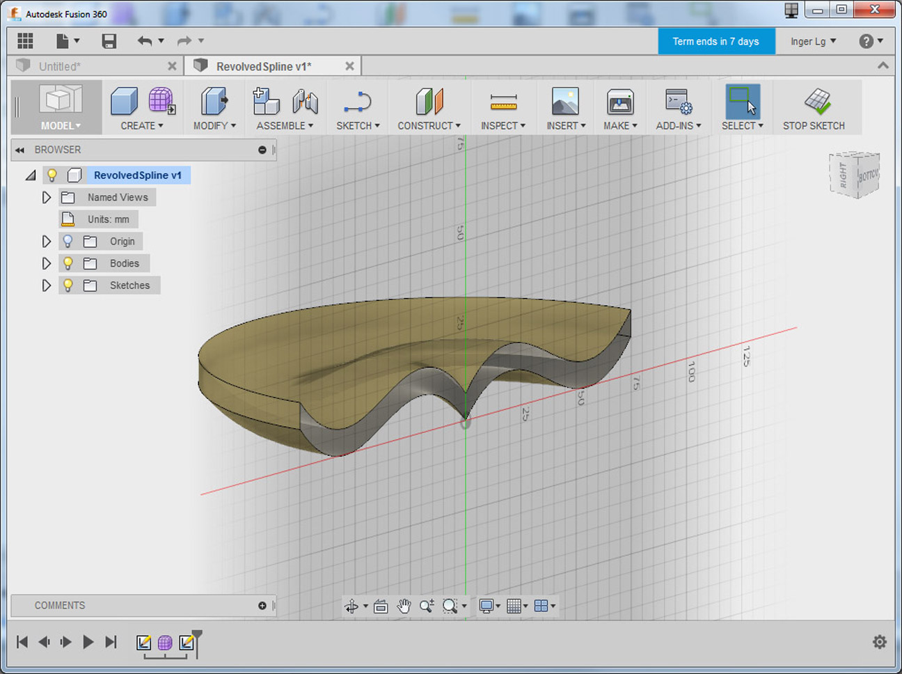
2.1
For my design of a small object that could not be made subtractively I used Fusion 360. I started by sketching a tilde, one of my favorite graphemes because it means both not (like in "not p"), as well as approximately and equivalent. I looked into several Sculpt options to see what kind of an object would result from applying these in combination with the tilde. Revolving the tilde 180 degrees around one of the axes resulted in (half) a curved flat plate that as far as I know can only be made additively. I saved the object as an .stl file.
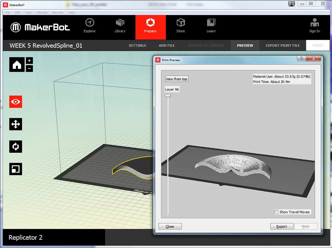
2.2
In MakerWare I checked the printing time and decided to make my revolved tilde even smaller than it already was because of the more than 2 hours required to print it.
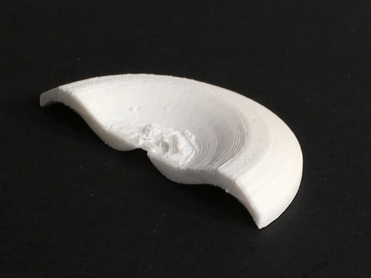
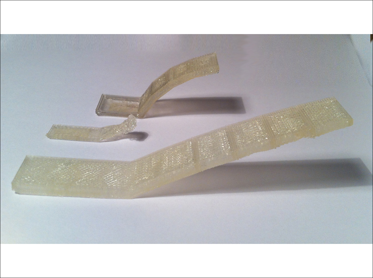
2.3
The final result: a beautiful 3D printed tilde.
Update: Later,when I showed my small object to our instructor(s), we discussed that this could have been done subtractively as well, by machining the top side first and then turn it up-side down to machine the bottom. This would not have been possible if the outer edges were curled in beyond 180 degrees.
Assignment 3: 3D scan an object (and optionally print it)
3.1
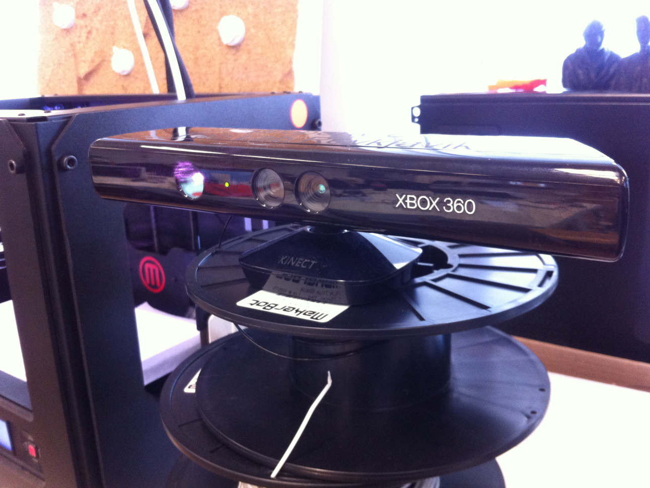
Out of the 3 scanning methodes introduced to us (Kinect, Memento, Modela, all using a different method to acquire data and convert these into a 3D model) I choose the first method because I wanted to do a selfie. The Kinect scanning method itself is simple: open ReconstructMe, press START, slowly turn around while sitting on a rotating chair in front of Kinect, save as an .stl file and done!
3.2
Because I already worked with the Replicator 2 printer for the first assignment of this week, I wanted to try the other 3D printer in FabLab Reykjavik being a Flashforge printer. I witnessed one of my collegues struggling to make this printer do what he wanted, because apparantly the settings choosen in the MakerWare software before exporting the print file overrule the settings on the printer itself.
3.3
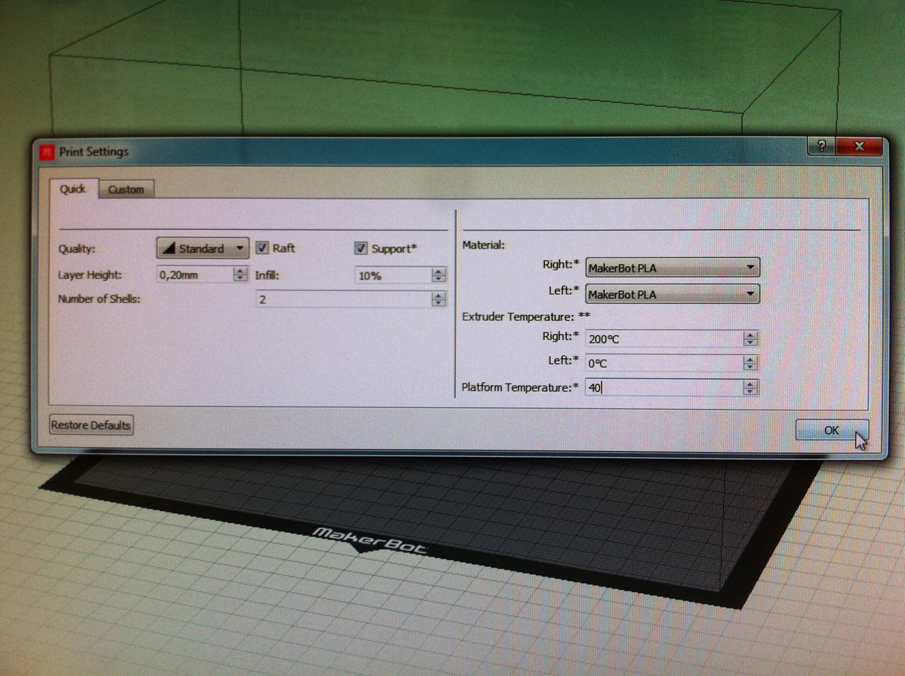
In order to avoid the kind of problems mentioned in 12, after importing the file in MakerWare I took care to really use the correct settings for the Flashforge printer before exporting the print file to the printer and I thought I had everything under control. However: to use this Flashforge printer - as I found out the hard way - one need some additional equipment too ...
3.4
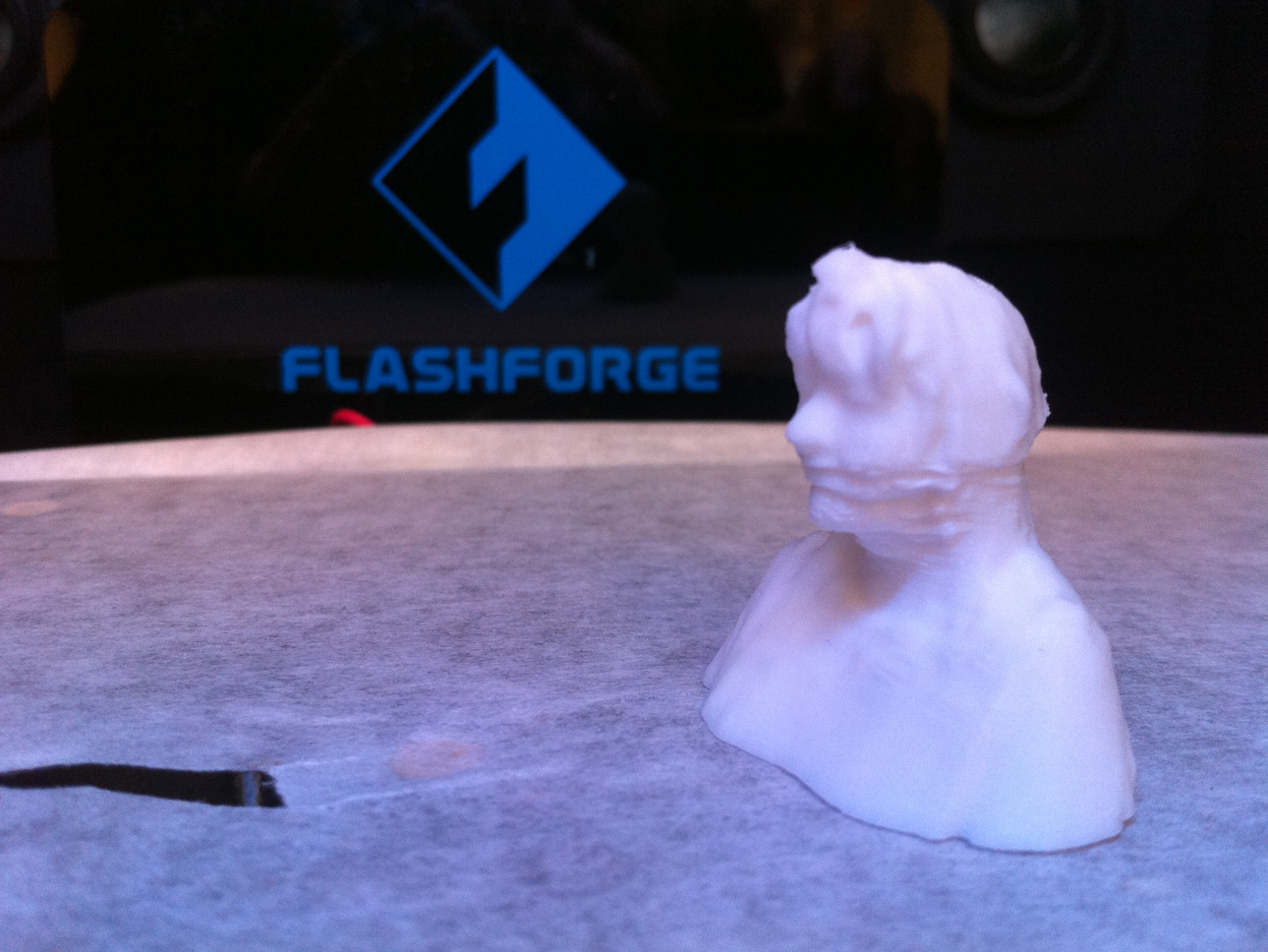
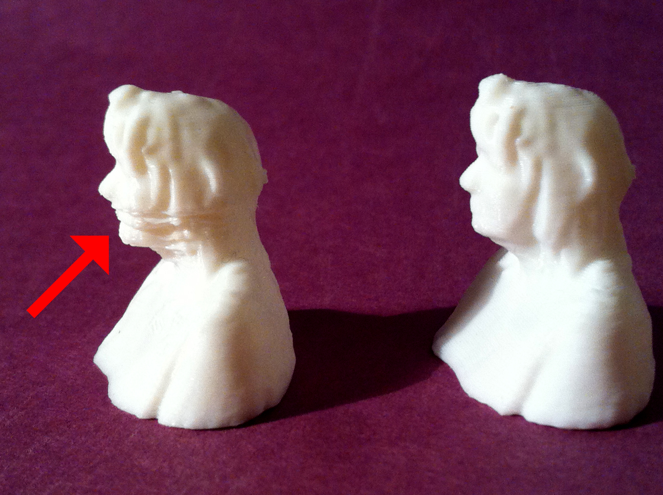
Halfway the printing process, when the surface to be printed per layer became smaller and smaller, the PLA did not cool fast enough to support the next layer! This resulted in an irregular, wobly surface instead of a smooth one.
3.5
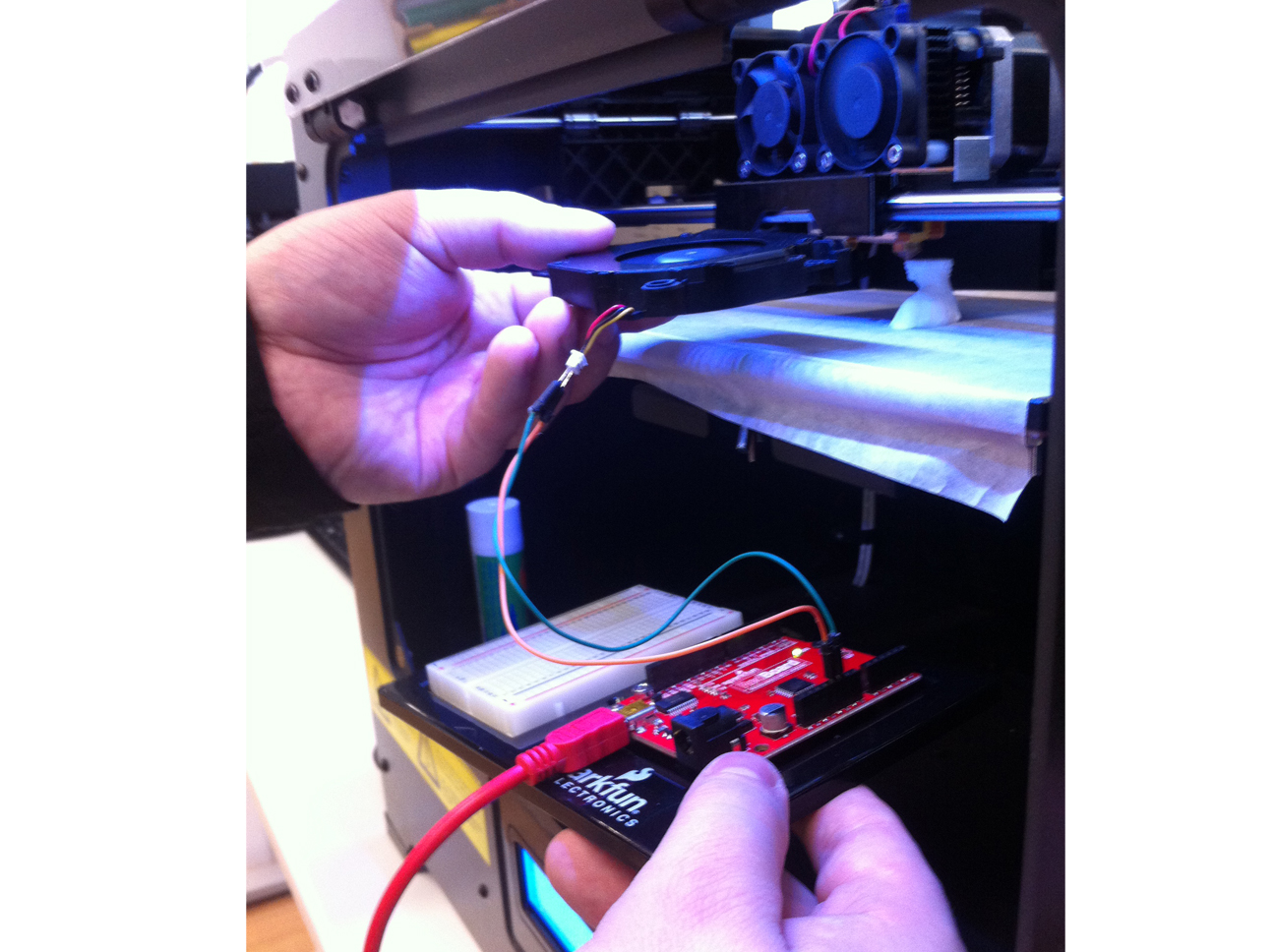
The extra piece of equipment needed to fix this problem appeared to be a small 5V cooling fan, powered by a microcontroller board and handheld for the remaining printing time!
3.6
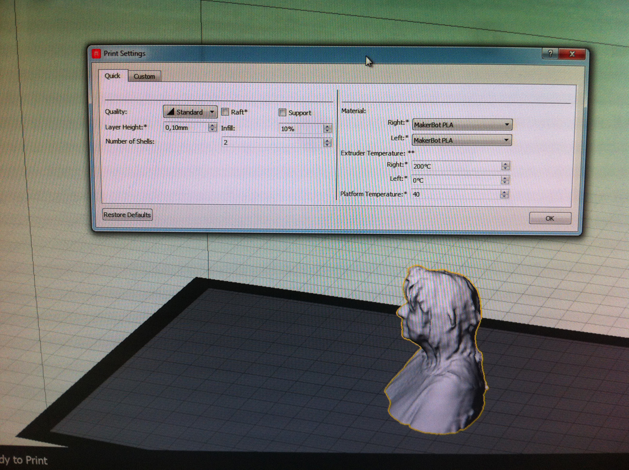
Because I wanted to be sure the problem was not due to lack of support (and because I wanted to have a better looking selfie ;-)) I checkmarked both raft and support and reprinted the little statue while using the handheld cooling fan during the whole printing process. The second selfie indeed looked much better and since the printer did not print any supports I concluded the problems in the first print (see red arrow) were really caused by the lack of a working cooling fan in the Flashforge printer.
FILES: All files of this week can be found here.
