
1
This week I started by doing some Fusion 360 CAM video tutorials, amongst which this tutorial for a Flat Pack Bookshelf that I thought was big enough for this week's assignment. I also found a .pdf file of the same tutorial.

2
Making the bookshelf consists of three parts. PART 1: Make the Model, starting with defining all parameters you think you will need. (Additional parameters can be defined later, but I learned it is good practice to start with as many parameters as you already can think of).
3
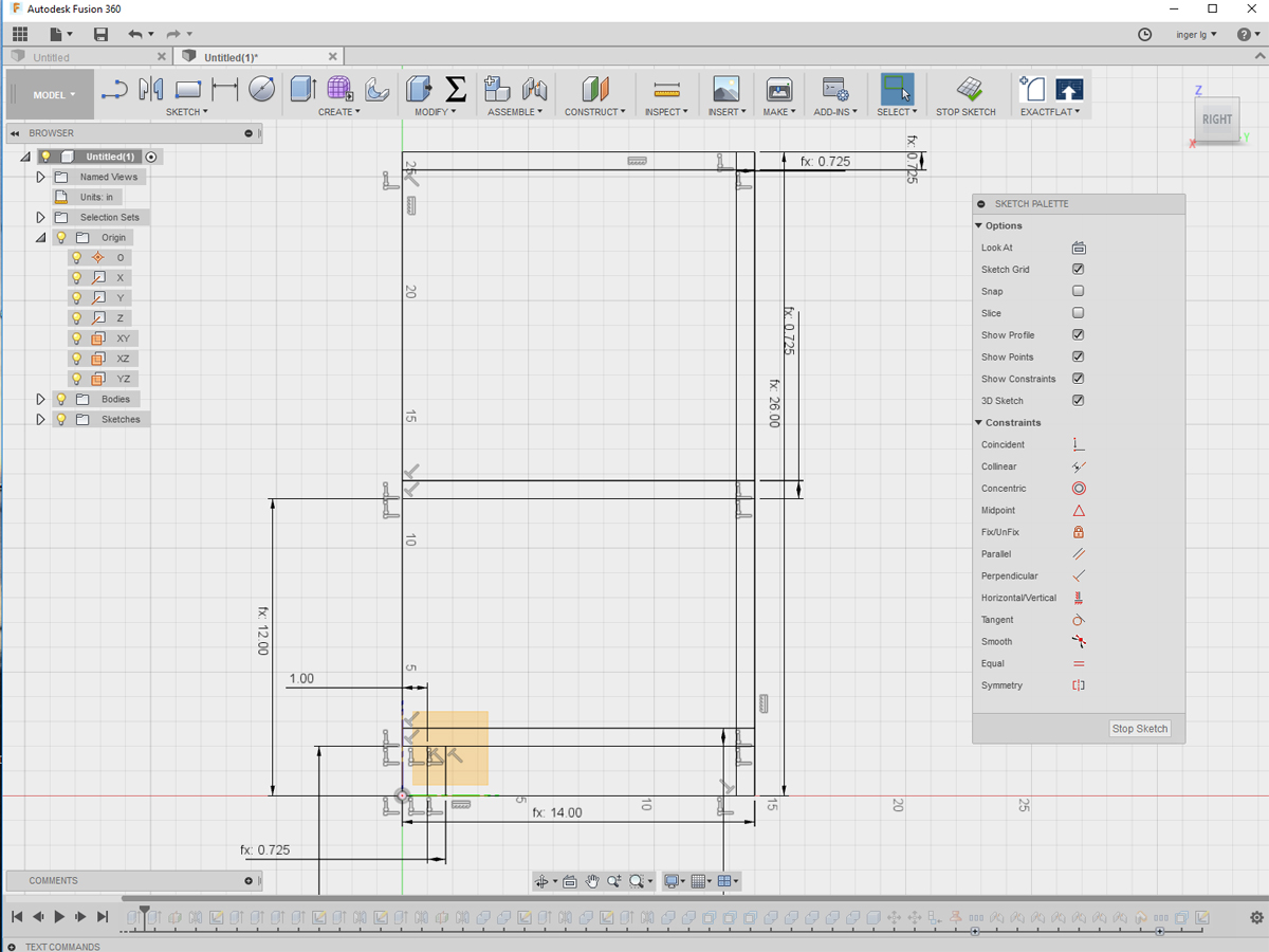
In another very helpful tutorial I learned these very important rules: always start with a 2D sketch, always start sketching in one of the planes, always start with a “nail” in the origin (so that the sketch is not floating around but tied in space) ....

4
... and always take care your sketch is fully defined through sketch relationships (constraints) and dimensions before next steps (extrude it out into 3D space etc.). (Fully defined sketches have only black lines. Underdefined lines are blue, as I found out far too late!)

5
By extruding sketch parts and mirroring parts around construction planes, all parts of the bookshelf were made, including a kick at the bottom.

6
Next step was to make the pockets, blindpockets and tabs, and the lips on the faces that have to be extended. By changing parameter values to test the model, at some point my model broke. It was then that I discovered the importance of "fully defined": some tabs were not attached to the parts. By using collineair and coincident constraints this was fixed.

7
To get a better idea about what the bookshelf would look like I changed the Visual Style from Wireframe to Shaded with Hidden Lines.

8
Now that everything needed for the bookshelf was created, the model has to be set up to be manufactured (PART 2). Stock was created for reference when laying out the parts flat.

9
In the tutorial the parts first were turned from bodies into components to make it possible to apply joints, allowing to create relative movement between parts. For laying things out on the stock and dragging them around this was very useful.

10
Setting up the model for manufacturing included adding clearance to the blind pockets and create dog bone fillets. I first downloaded this Dogbone add-in and then watched this How to video to understand how to use it.

11
It took a while to apply dog bone fillets to all roughly 150 corners that needed fillets, but at the end all looked fine. Unfortunately it was true what already was stated in the tutorial: later, when I changed some parameters (Ply, being material thickness) I had to re-apply the feature.

12
Once the model was set up for manufacturing it was time for PART 3, being to switch from Fusion's Model environment to the CAM environment and follow the Cam Setup instructions. For the settings I used the information we got from our instructor/ guru Bas about tools to use, downcut first, upcut second and so on.

13
In Fusion 360 the toolpath can be pre-viewed for each setup separately, like in this case the 2d Contour5 path for the outsides of all parts.

14
In Actions/ Simulate a full simulation can be seen of toolpaths, including removal of stock material. This is very handy to check if you did not forget anything or made other errors.

15
I created 8 setups, being both a downcut to start with and an uppercut to get the full cut depth for all 4 toolpaths. (Apart from the 3 toolpaths for the Blindpockets, pockets and external contours a 4th toolpath was to be created later for additional screw holes, to be positioned according to our instructor's "screw diameter + tool diameter + 3mm margin from toolpath" mantra).

16
In a direct Fusion 360 to ShopBot workflow the last step would now be to post process the toolpaths and generate the ShopBot files by selecting ShopBot OpenSBP in the Post Configuration settings. Since there was no experience with this workflow in our FabLab, I decided to follow the standard workflow and do a VCarve in between step. (I intended to later realize the direct Fusion 360 - Shopbot workflow.)

17
For the VCarve step in between, all parts were exported from Fusion 360 as separate dxf files. These files were imported in VCarve, the parts were layed out flat, toolpath setups were made and toolpaths created.

18
Using the ShopBot TC option in the VCarve post-processor, the .sbp files for the ShopBot were created.

19
Although our instructor gave a very detailed instruction about how to use the ShopBot, this Icelandic Öryggireglur (made by two former Fab Academy students for use in our FabLab) was a fantastic aid to remember all steps.
20
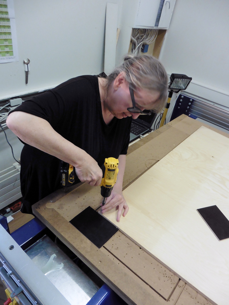
First step: tie your hair (not in the instructions, but very important security measure) and use the spacers to screw the stock at the right place to the spoil board.

21
The right tool for the first job was inserted and the dust hood put back in place, which required some effort because of the way it is attached from behind to the ShopBot.
.png)
22
First job to run: make small holes at the spots where additional screws are needed to prevent movement of stock while cutting out the parts.The .sbp file for the job was loaded into the ShopBot control software, the head positioned correctly (magic K: X Y Z window will appear) and I then just followed the Icelandic instructions to execute the job.

23
When this pass was finished, next step was to carefully look where the small holes were and put all screws in, which in our lab required to climb on the Shopbot to reach certain spots.

24
Following the instructions one by one all jobs were executed and tools exchanged in between when needed. All in all this took quite some time. When making appointments for future projects it is good to keep this in mind!

25
Before removing the parts from the table it is good practice to check whether or not additional passes are needed, for instance: because it turns out the tabs will not fit in the pockets.

26
Thanks to our instructor Bas I learned about this just in time! He measured the pocket width, that seemed OK for a stock thickness of 15.6 mm ....

27
.... but a pocket lenght of 76.31mm ....

28
.... is really too small to fit in a tab of 76.59 mm.

29
The problem was solved by adding an extra pass removing some millimeters of material from the tabs, which seemed the easiest fix. A separate toolpath for this was created in VCarve. In cases like this the big advantage of Fusion 360's fused Model and CAM environments is obvious, since toolpaths are easily re-generated when changes to the model are made.

30
After having run the extra pass, the tabs seemed to fit in the pockets. Such a test should have been done first. Important lesson learned: for critical parts that have to fit, make a test corner in your design to be executed first as a separate cutting job to check if the design is right.

31
To separate all pieces from the board, instead of cutting the tabs (difficult to reach because at the bottom of the board) all screws were removed so that the board could be turned around completely.

32
Disadvantage of this procedure: some parts will fall out and chips will come off. Solution for this - as shown by Bas - is to put glue on the chip ...

33
... put the chip in place ....

34
... put pressure on it and go home.

35
The next day all remaining material of the tabs was sanded away.

36
The surfaces of all parts were sanded too ...

37
... and the parts were press-fitted together into the right order:
1. kick into bottom shelf
2. shelves into back plate
3. attach sides
4. attach top piece

38
Sometimes it was more press-hitting than press-fitting (never hit directly on the plywood, I learned) ...

39
... but at the end there is was: Flat Packed Bookshelf number one. I intend to make a second one, once I have setup the direct Fusion 360 - ShopBot workflow. UPDATE: for the Composites assignment I realized the direct Fusion 360-ShopBot workflow, but due to other obligations I have not made a second bookshelf yet.
FILES: All files of this week can be found here.
