Assignment: Group assignment: Characterize your lasercutter, making test part(s) that vary cutting settings and dimensions. Individual assignment: Cut something on the vinylcutter. Design, make and document a parametric press-fit construction kit, accounting for the lasercutter kerf, which can be assembled in multiple ways.
We got introduced to the Roland GX 24 vinyl cutter and shown how to turn it on, set it up for different materials and position the material to be cut. Also how to create a vector graphic in Inkscape or import a bitmap graphic and convert it to a vector and set a 0.02mm outline that the cutter understands. It was pointed out that the machine is by default set to cut the various rolls of vinyl in the Fab Lab's inventory, but to make sure that if we will cut different materials, for example copper foil, to reset the machine for the next user, to minimize wasted time and materials.
I drew a picture of an insect's outline on a piece of paper and as I did not have a scanner at home I took a photo of it and opened it in Gimp. I selected outside and inside of the line, inverted the selection and painted the line black. This I then opened with Inkscape and made it trace the bitmap. I ended up with two lines, along the inside and the outside. I decided to keep the outside one and proceeded to simplify it by decreasing the number of nodes by about a factor of 5, this did not unduly affect the shape of the drawing, but should cut the time the vinyl cutter takes to cut out the design. Now I had two parallel lines and being a complete Inkscape novice I could not figure out how to separate them and get rid of the more complex one. Fortunately Arnar Dadi made short work of showing me how to ungroup them and I have saved it as a PDF document with a 255 red line, 0.02mm thick.
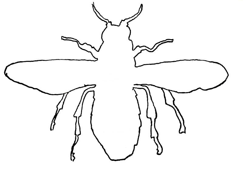 Raw insect drawing
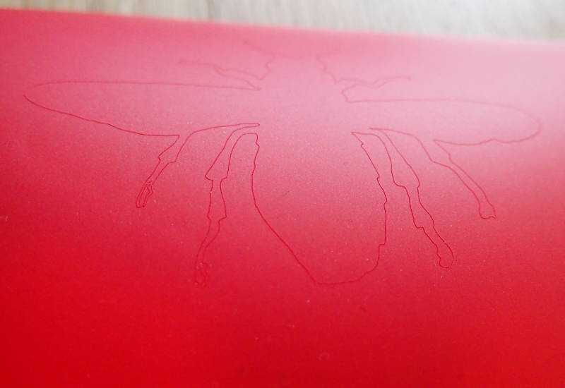 Fresh off the vinyl cutter.
I lost the original, so I cut another copy and stuck it to my final project.
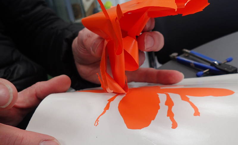 Peeling off the surrounding vinyl.
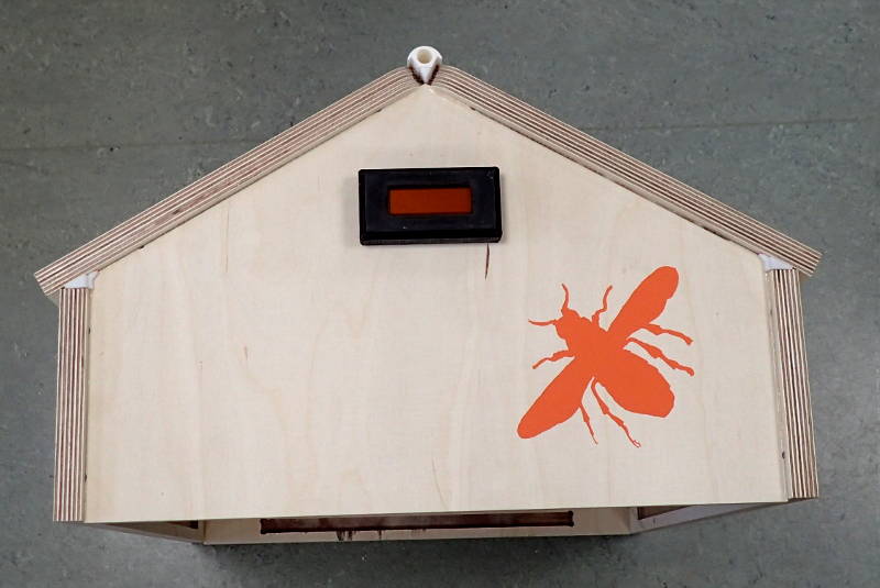 It has found a home.
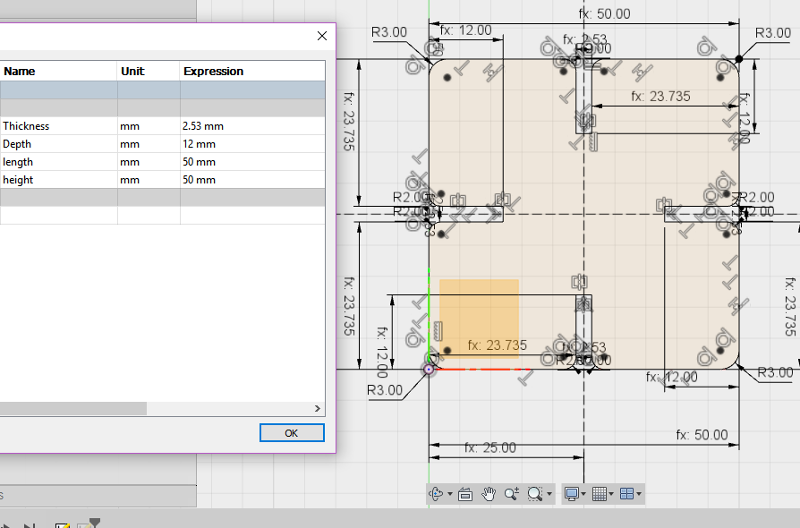
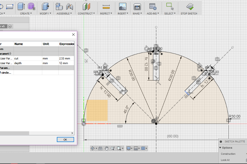
I decided to design a simple press fit piece in Fusion 360 and put constraints on it to make it parametric, so I only have to alter one number in the User Parameters setting to change the kerf width and the piece can be resized without it exploding. I put a 2mm fillet to round off the mating corners of the tabs so they will slide together more easily, this had me stumped for some time as the fillet command in the Modify menu will not work on a 2d sketch, there is another one in the Sketch menu which works a treat.
I saved the sketch as DXF, which is not found in the menus, but by selecting the sketch in the document browser in Fusion 360 and choosing Save as DXF. I then opened it in Inkscape and set it to No fill, stroke red 255 and stroke width to 0.02mm. I saved it as a PDF at 600dpi and selected to use the exported object's size and set a bleed/margin at 2mm to make sure the line surrounding the document would get drawn all the way around it. To get it from my laptop to the laser cutter I transferred the PDF file to a USB stick and opened it in a computer that is permanently set up to serve the laser cutters. In the print dialog I chose a 600dpi resolution, job type as vector and the vector settings appropriate for cardboard, speed 30%, power 80% and frequency 500hz. The laser cutter used does not have an automatic air compressor, so before starting the cut I made sure it's compressor was turned on and the air extraction system was turned up to it's highest setting. I was starting with a fresh piece of cardboard, so I set the starting point in the top left corner. This was the first piece I made and as a handy little confidence booster it turned out with perfect fitting kerfs on the first go.
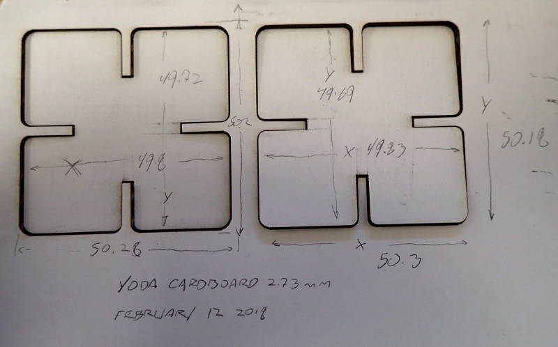
I did some test cuts in cardboard and the kerf proved to be 0.47 - 0.49mm, so I cut the slots in the pieces to be that much narrower than the thickness of the material.
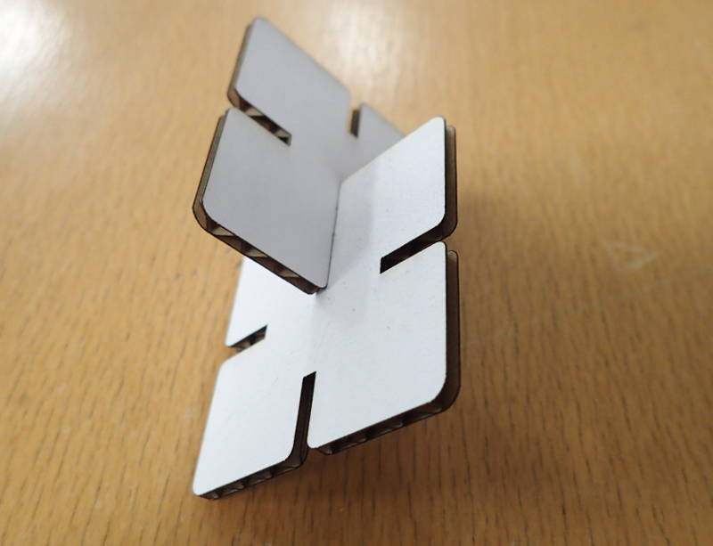 The first laser cut pieces.
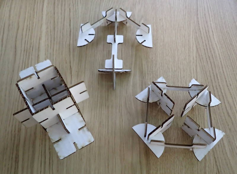 Examples of press fit models.

Basic_press_fit_element_v6.f3d
Here are some PDFs, ready for cutting.
Our group assignment was to cut out a test piece on the Epilog mini 24 laser cutter in various materials and measure the kerf in order to be able to design some press fit pieces out of cardboard. We cut some 50mm squares out of 4mm MDF, 3.12mm acrylic and 2.8mm plywood. The lab has two laser cutters, Yoda and Leia, we cut the MDF and plywood on both machines to see if their calibration was noticeably different, but the acrylic was only cut on Leia, as that one has a more powerful air extraction system.
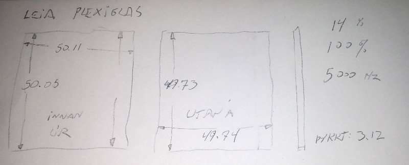
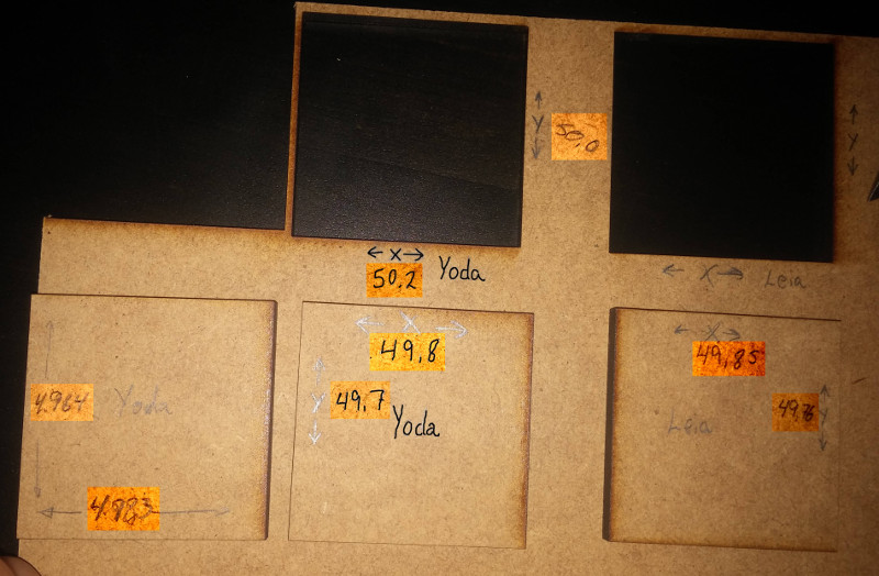
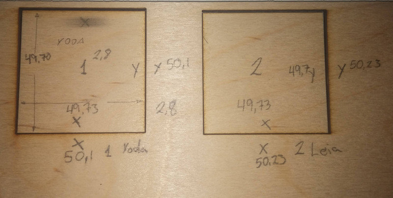
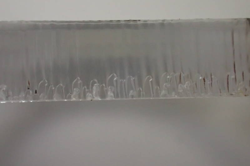
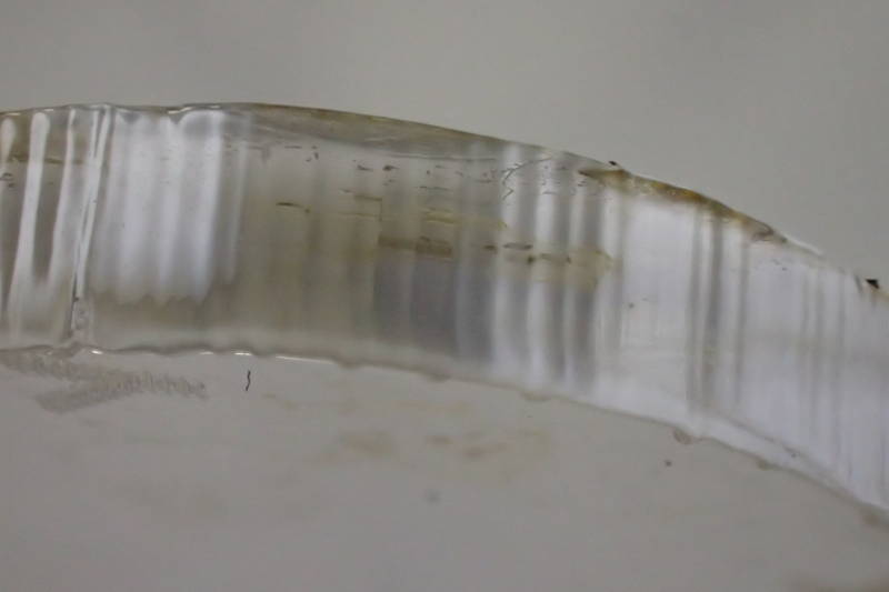
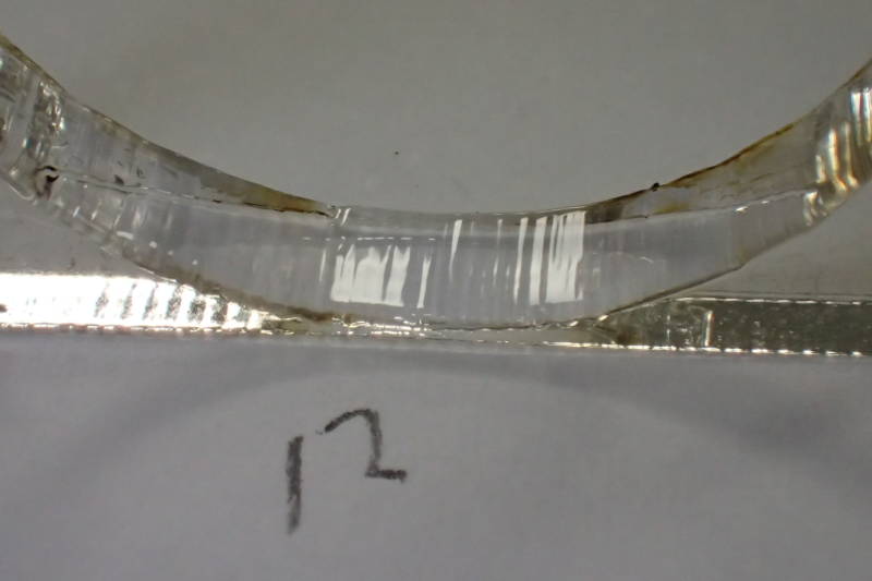
We tried cutting a test piece on both cutters out of acrylic with varying speeds, at too high a speed the beam did not penetrate fully, leaving a serrated edge on the underside. At too low a speed there was evidence of scorching. The ideal speed proved to be 14% on Yoda, but 13% on Leia, although Leia has a new tube, as of october 2017. We also tried 2.8mm plywood, there the speed could quite high, 29% on Leia and 26% on Yoda. The preset for 4mm wood is 12%.
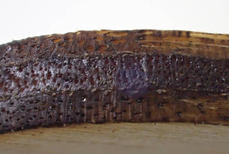 Laser cut edge of 2.8mm plywood.
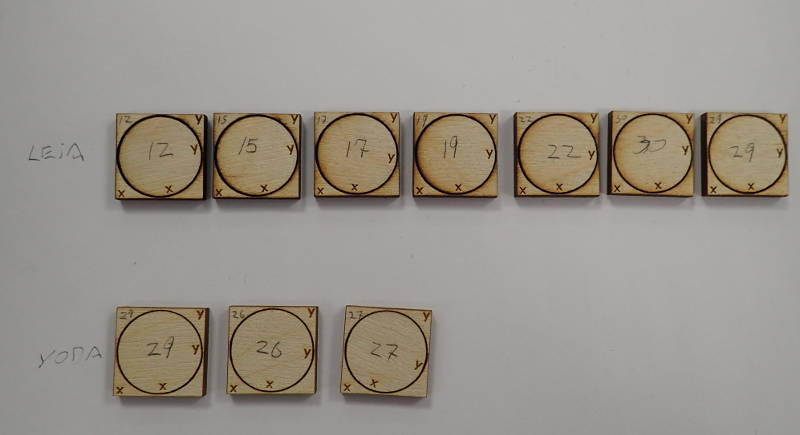 20x20mm plywood test pieces with cutting speeds.
 Outside edge - ideal speed.
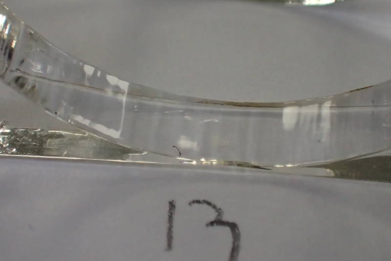 Inside edge - ideal speed
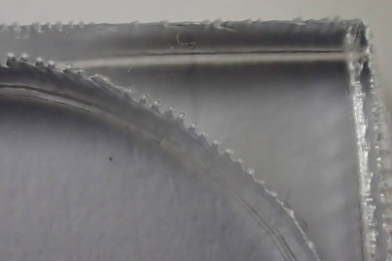
 Speed too high - incomplete penetration - pieces stick together.
 Speed too high - Popping pieces apart leaves a serrated edge on underside.
 Speed one percent too high - outside edge.
 Speed one percent too high - inside edge.
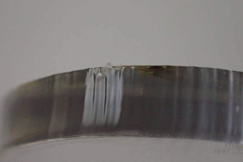
 Speed one percent too slow - outside edge - slight scorching apparent.
 Speed one percent too slow - inside edge - slight scorching apparent.
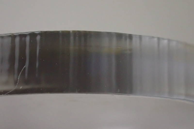
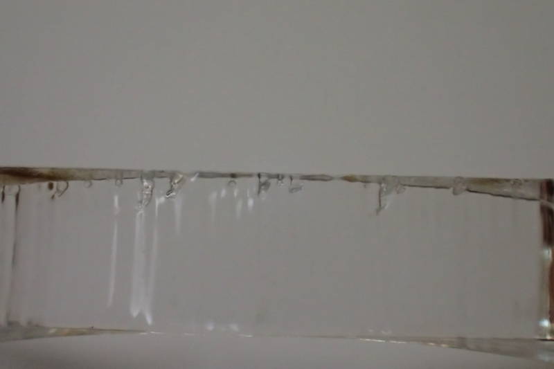
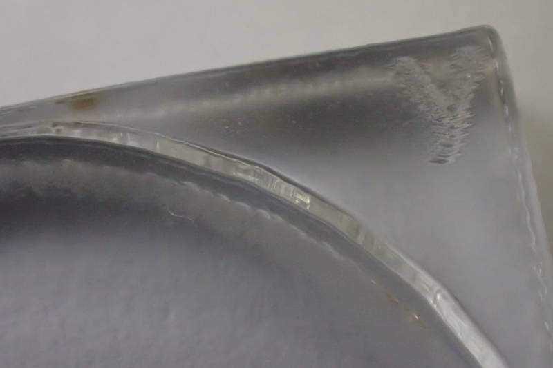 Regardless of speed, top side of kerf in acrylic looks good.