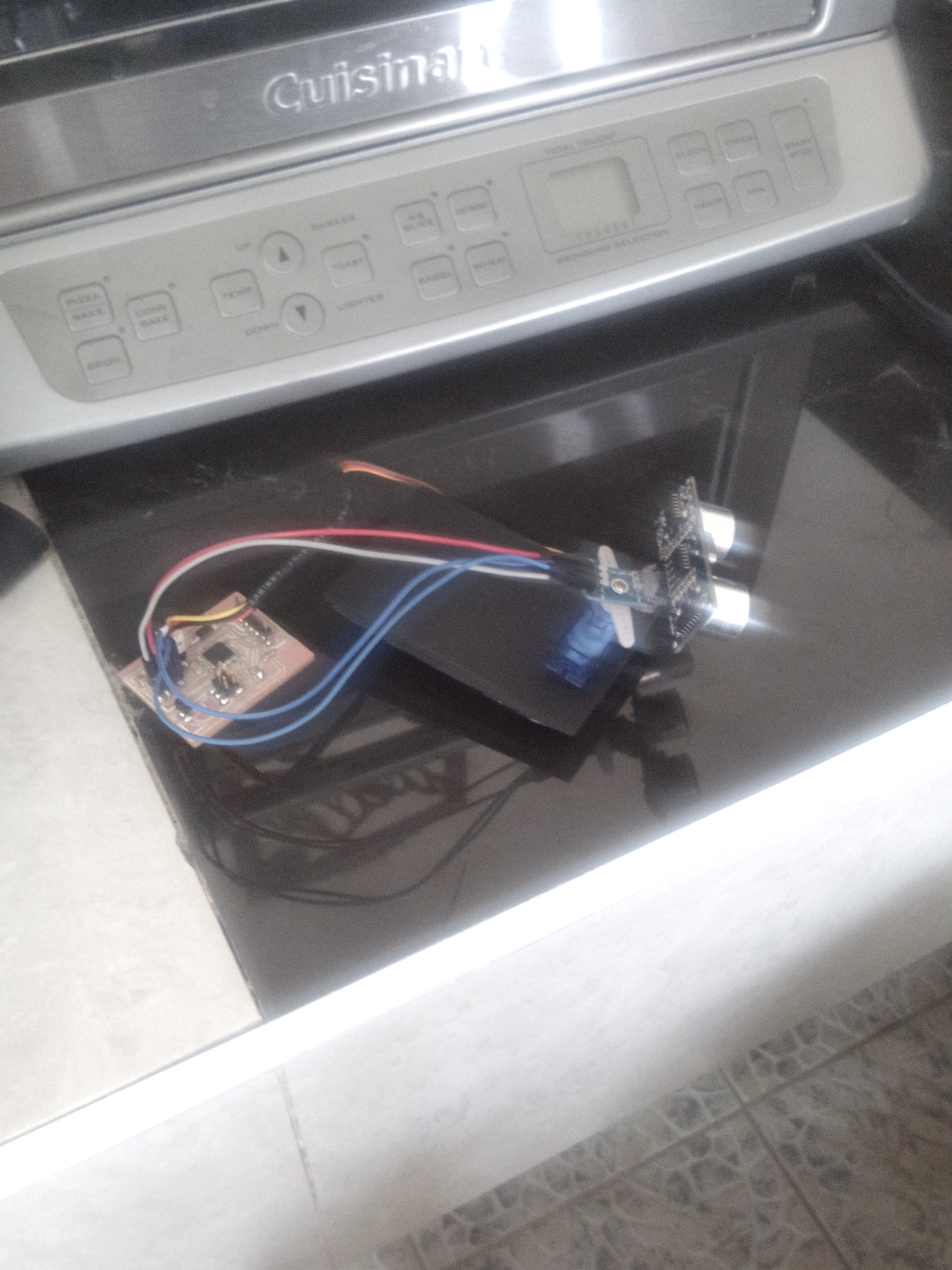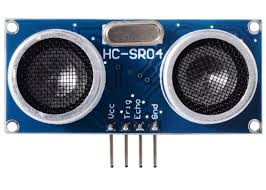
that sensor is used to truck the birds as in put by using ultrasound
about output we have two things
first we have motor
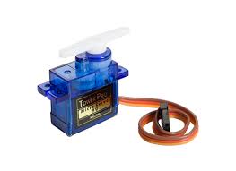
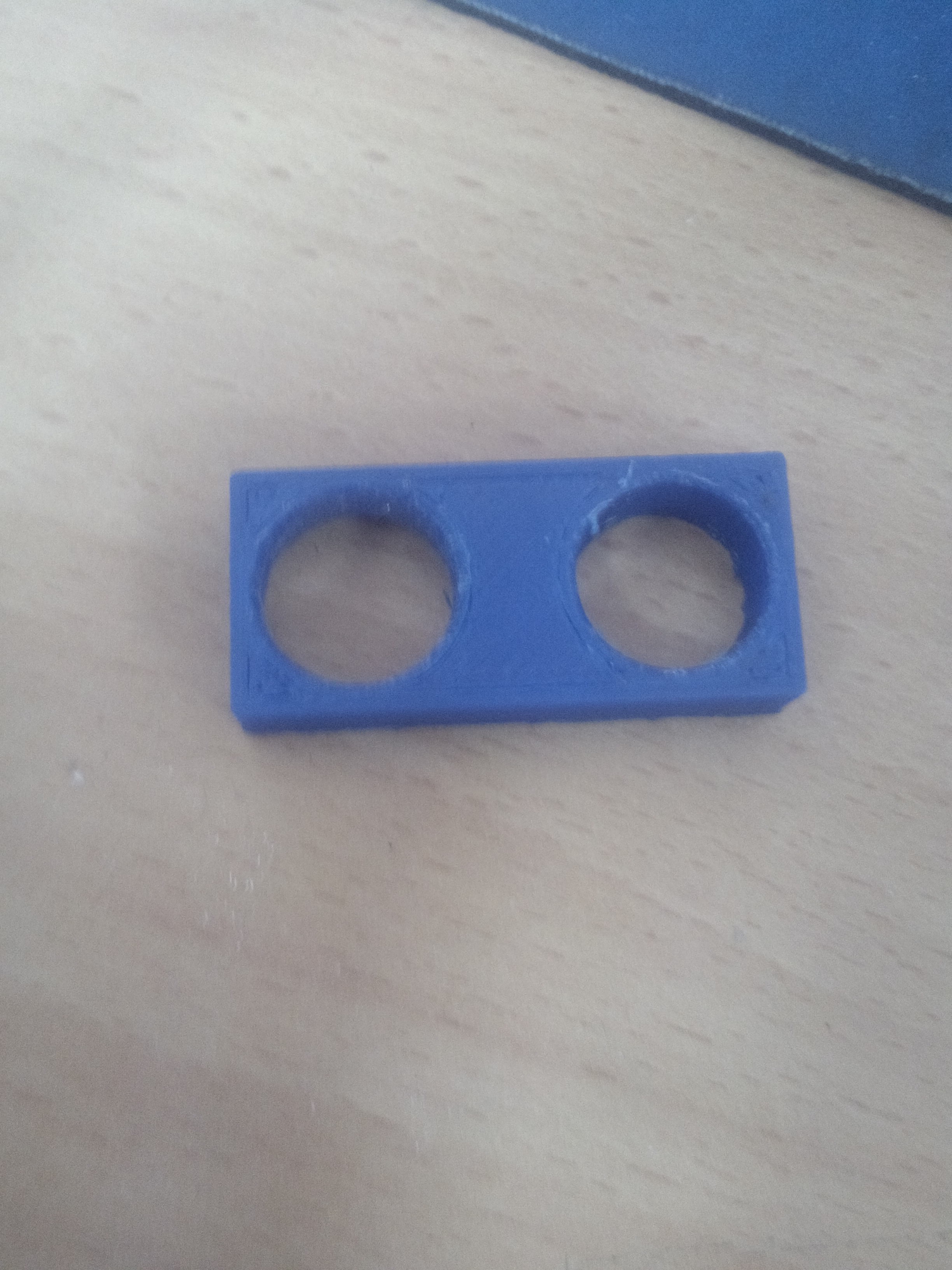
we use that sensor to rotate the ultrasonic sensor because that ultrasonics sensor is to capture the birds in from 15 up to 165 degrees.
the second is buzzer
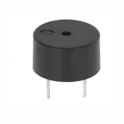
using that buzzer to produce the sound.
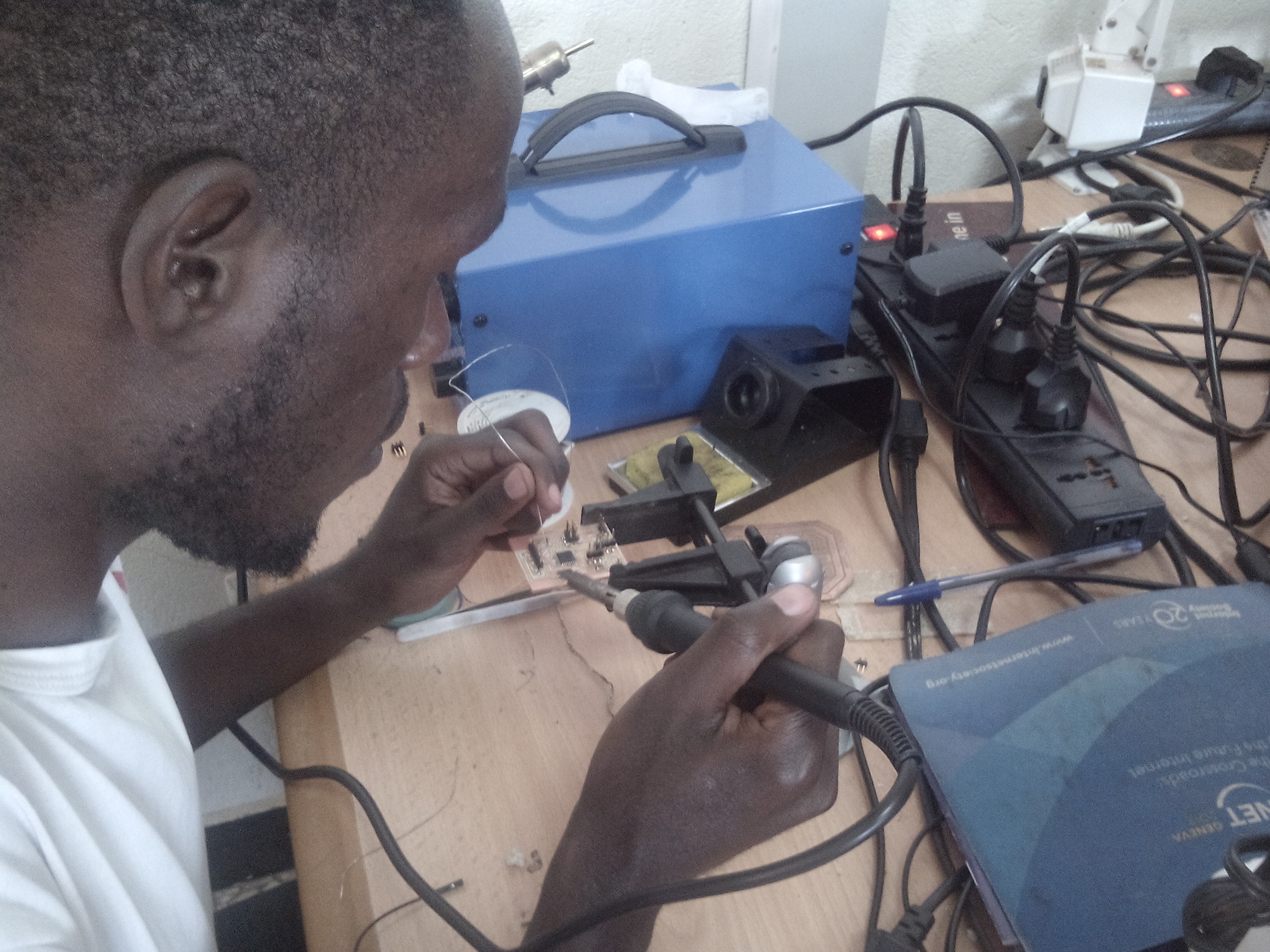
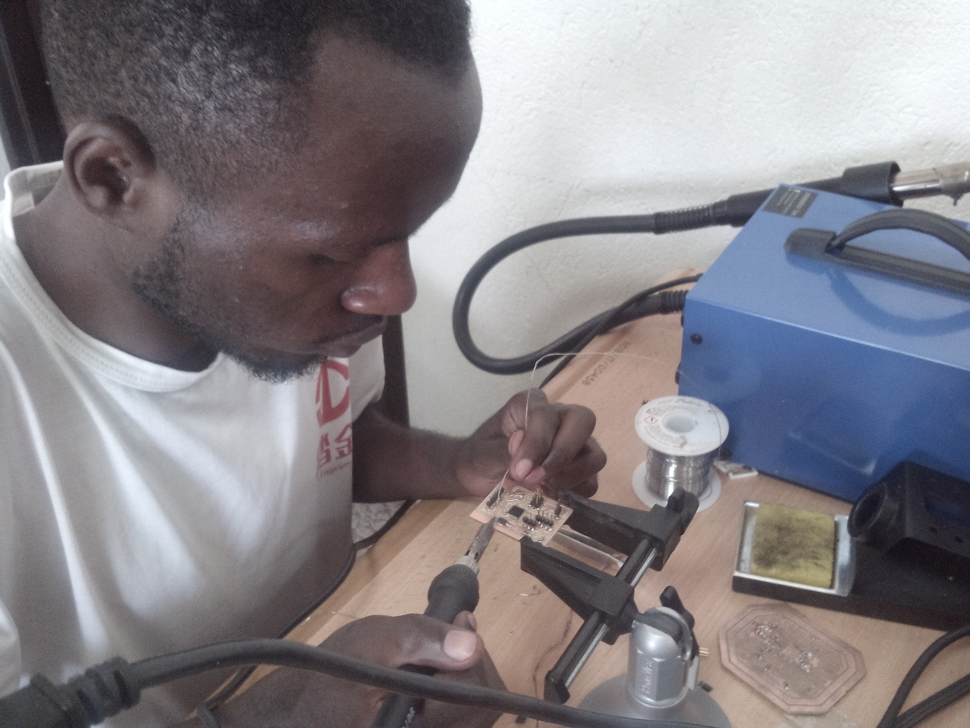
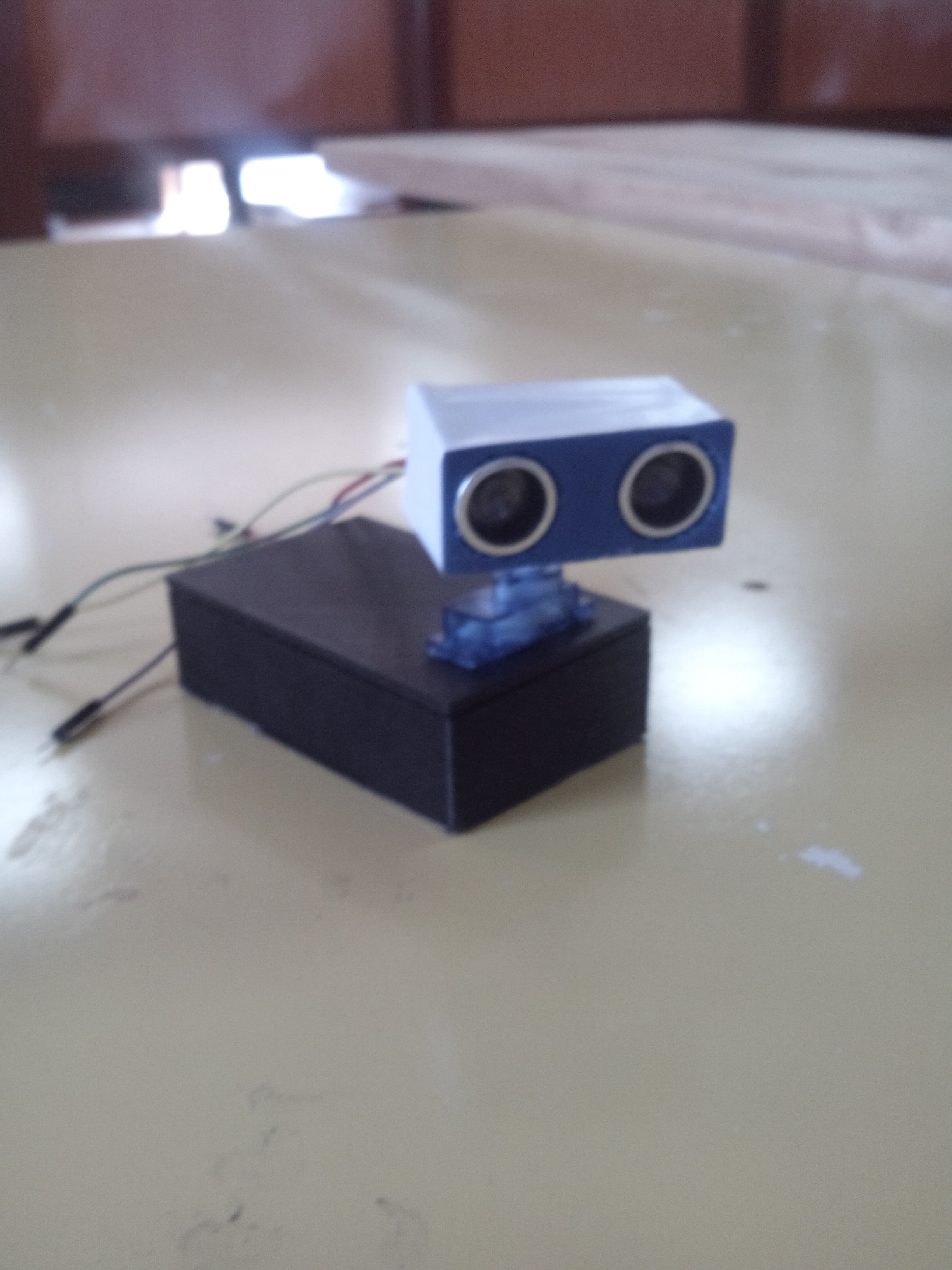
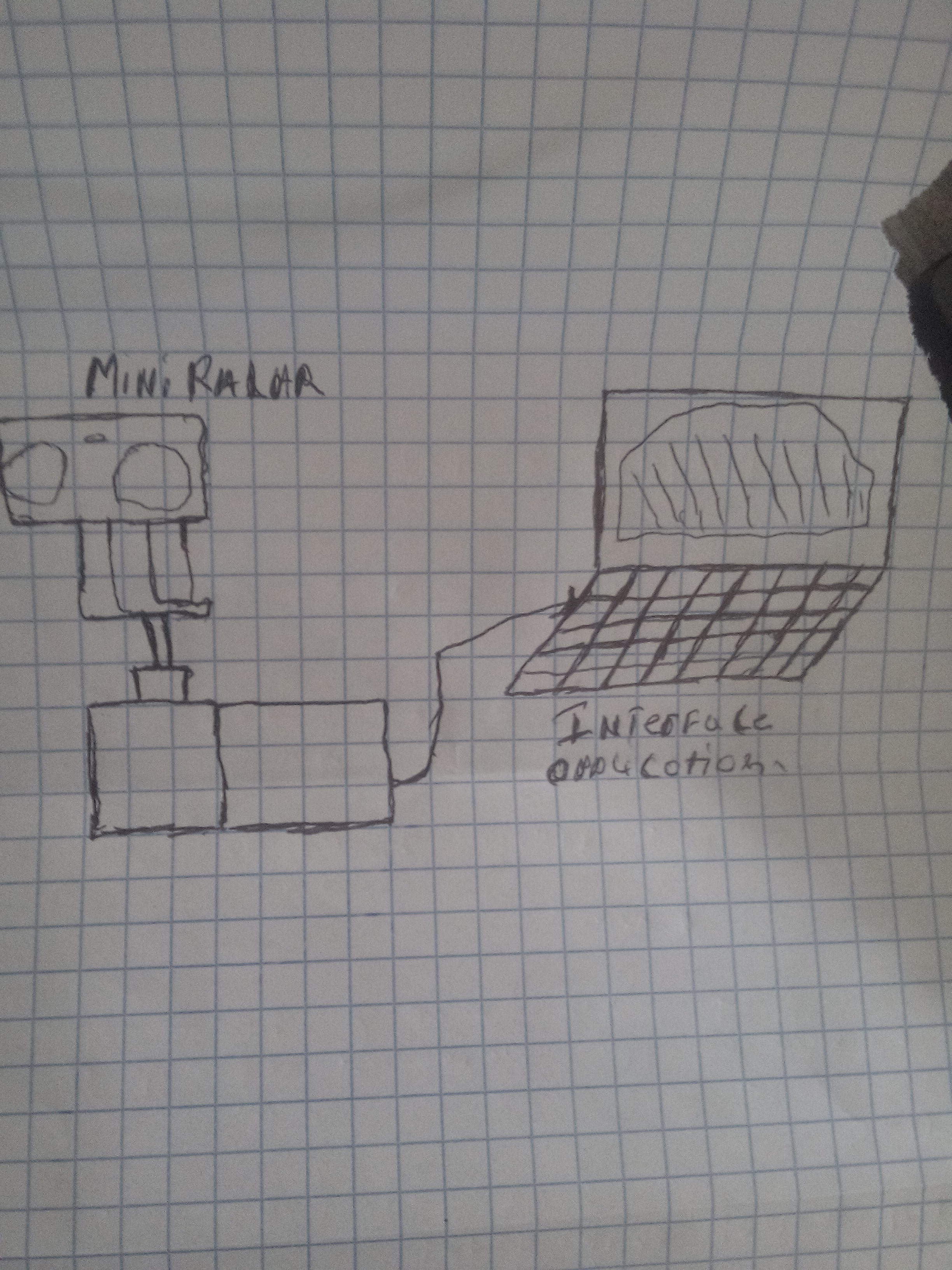
that are the picture that are demonstrate how my project working.

I have proposed the idea in the first week of fab academy and I had made a rough sketch of the projectmy project proposal called mini radar by using the ultrasonic and arduino my project it have the input output and we have the application interface and connect the aplication interface by using serial communication in my project the input are the ultrasonic sensor using to detect the object by using the ultrasound. and the output are servo motor using to rotate the ultarsonics sensor and buzzer using to produce the sound if there is an object and my project i use to create the sound that are using to avoid the animal in our field like cat,dog,snake and birds.
The major steps of this project are :
design
building hardware
make controller
Developing GUI
The processes I have gone through are :
3D Design
3D Printing
Electronics Design and Production
embedded programming
output device
input device
interface and application programming
networking and application
In parts of design
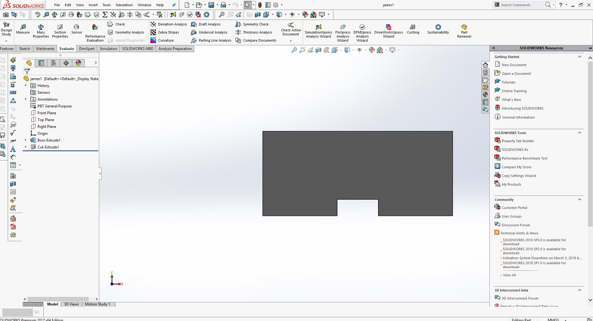
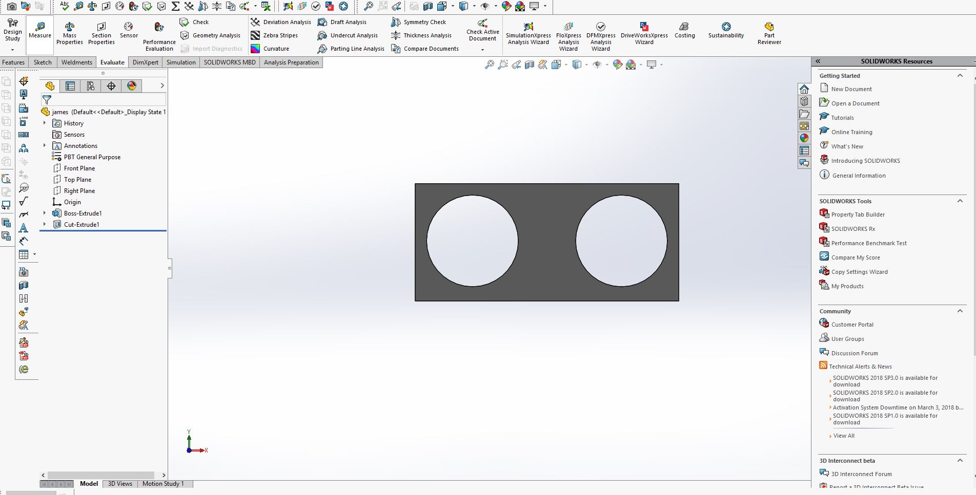
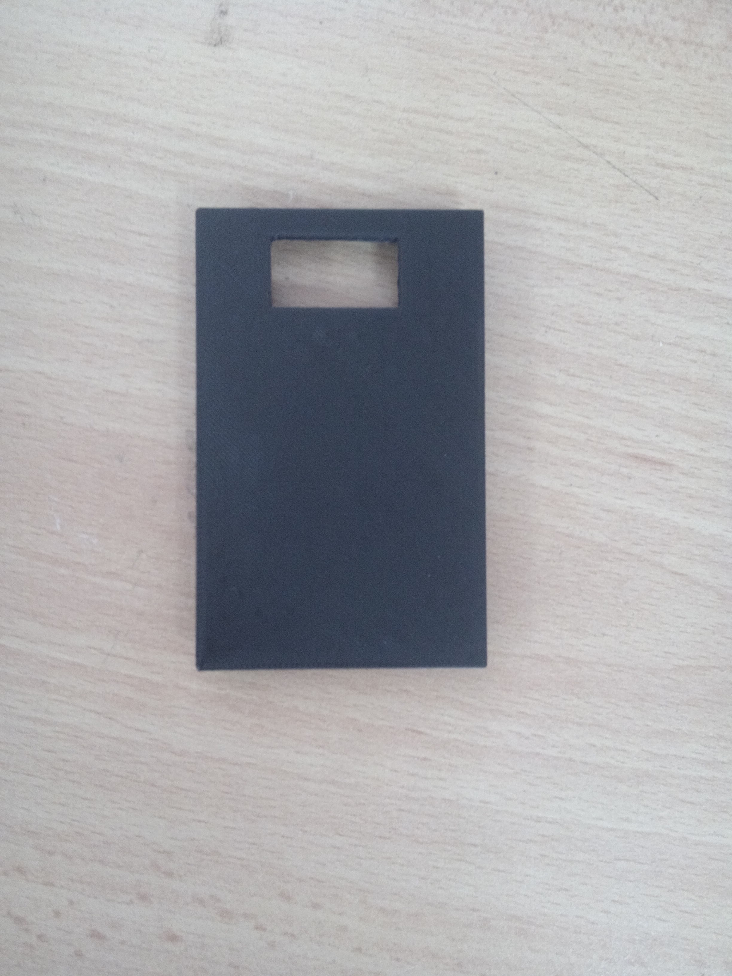
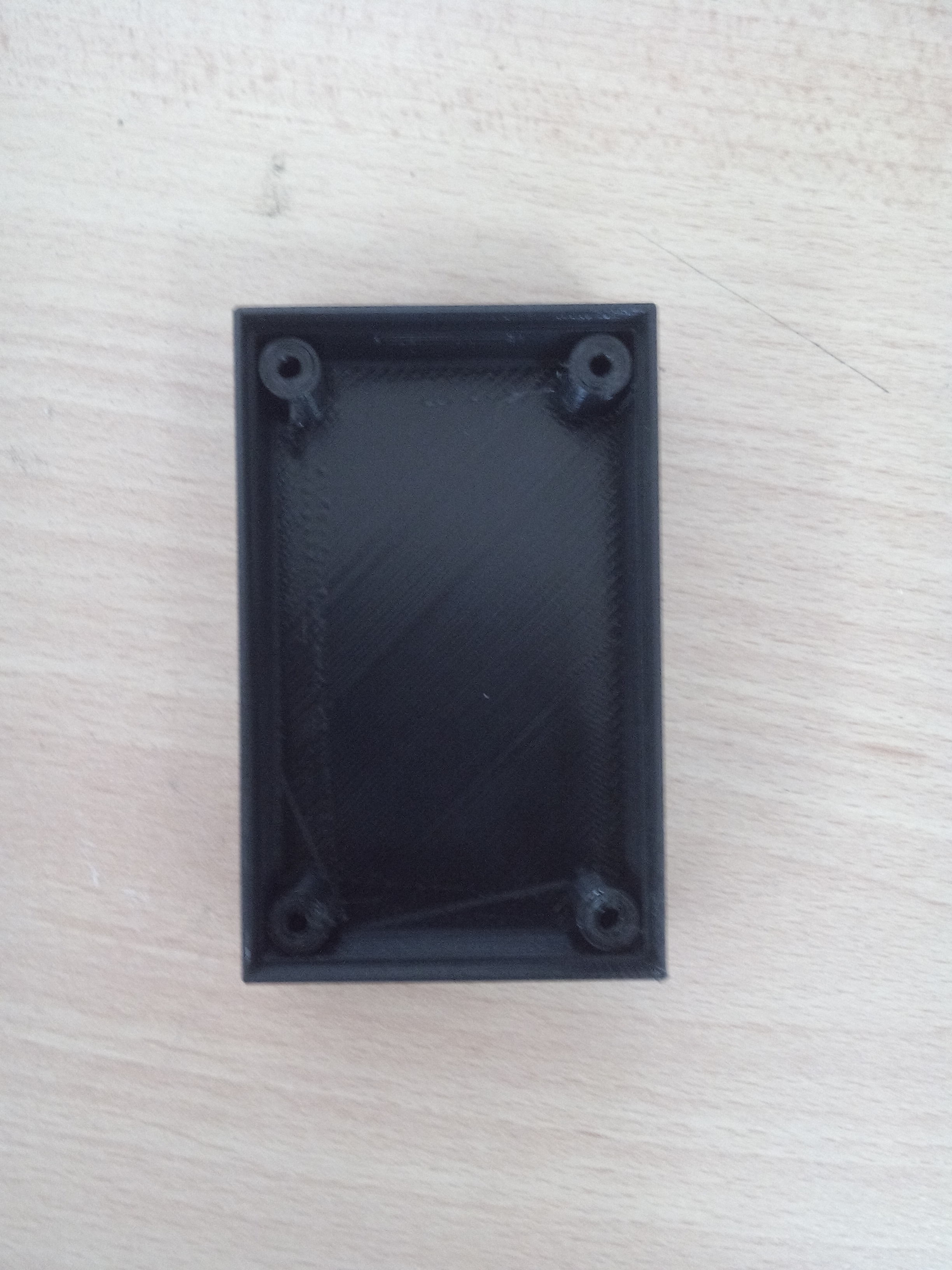
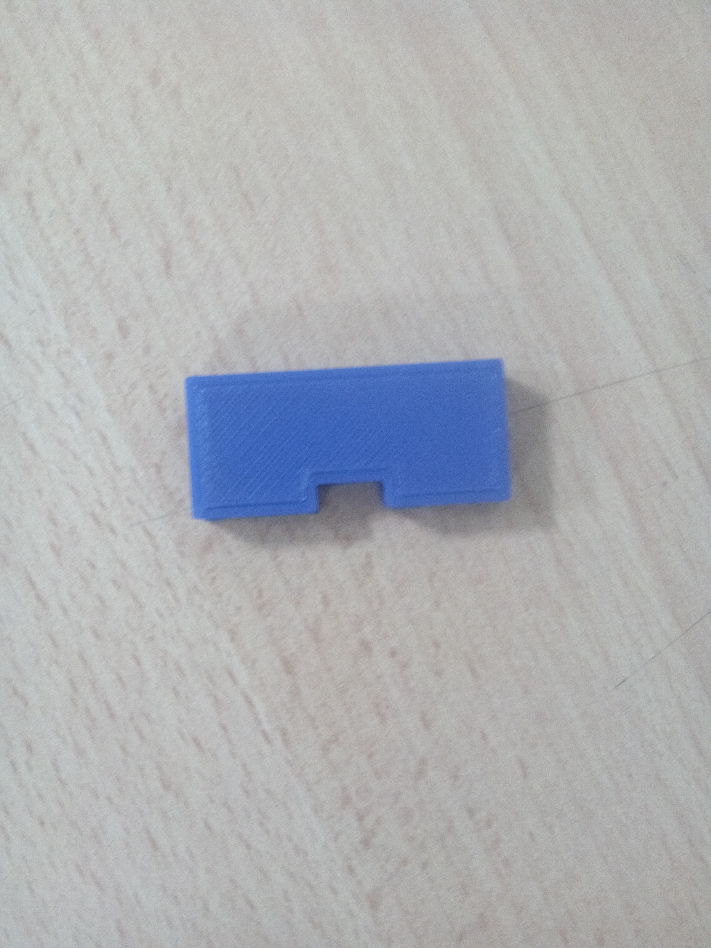
I have made some CAD design in the week of Computer Aided Design itself a bout in design we design the cover in soldworks means that we use 3D in my design first is the cover of my project
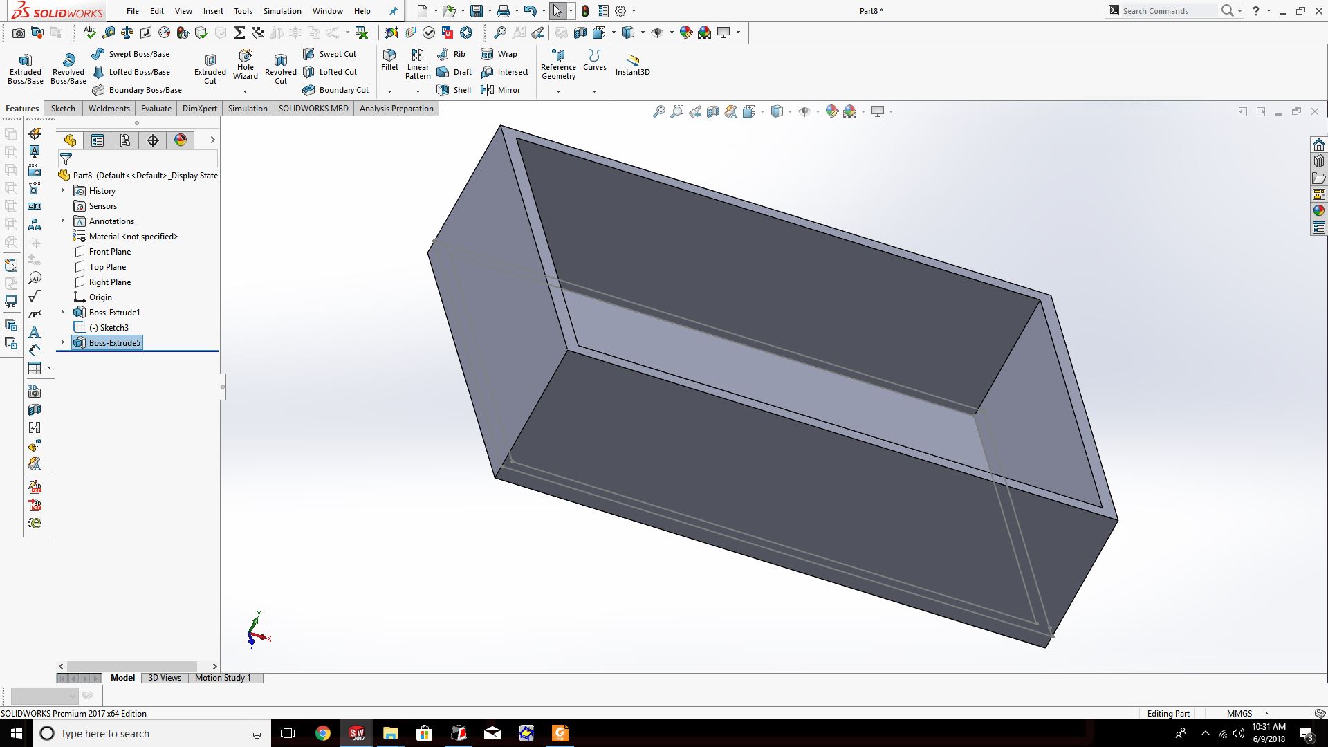
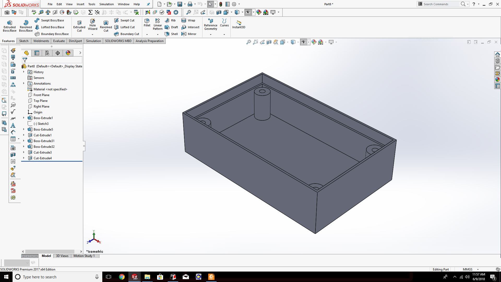
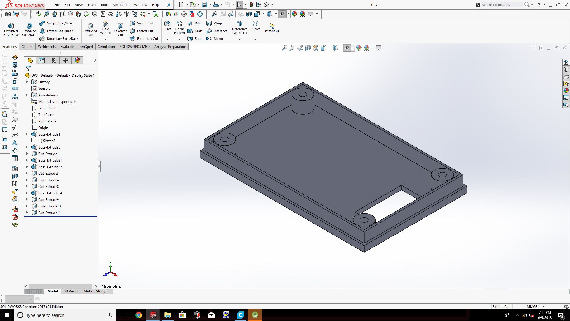
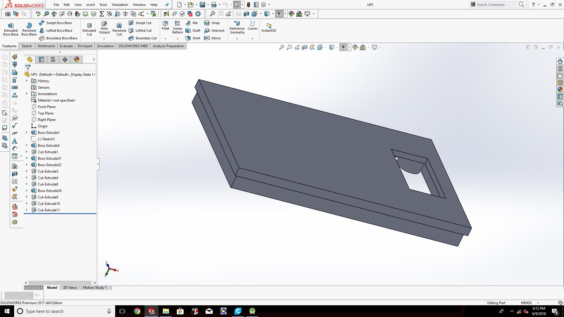
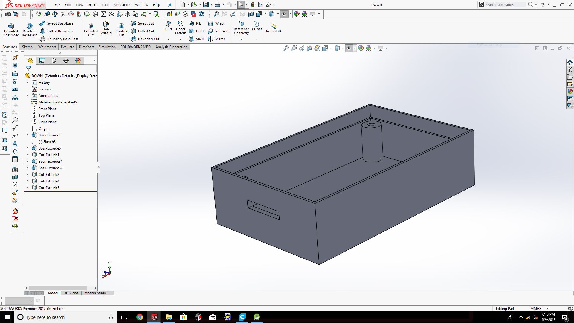
see all part of 3D
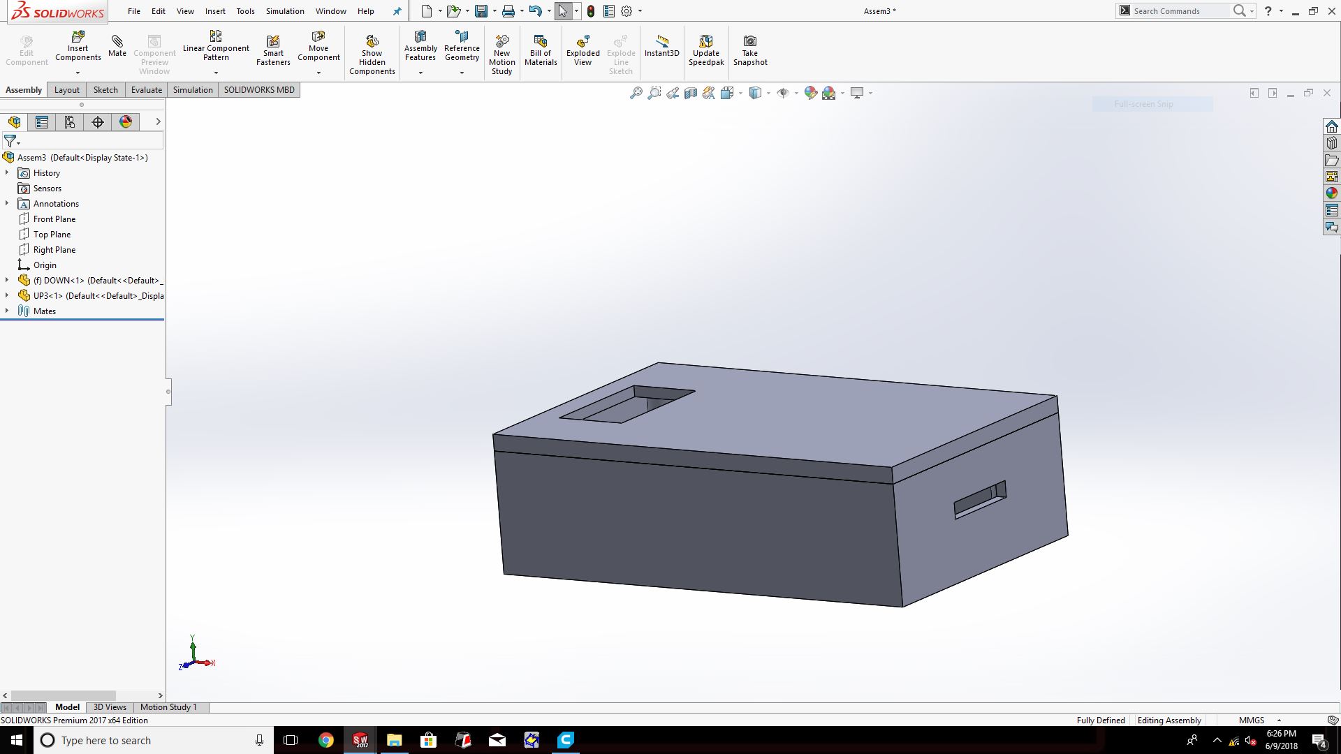
here im design the cover of ultrasonics sensors
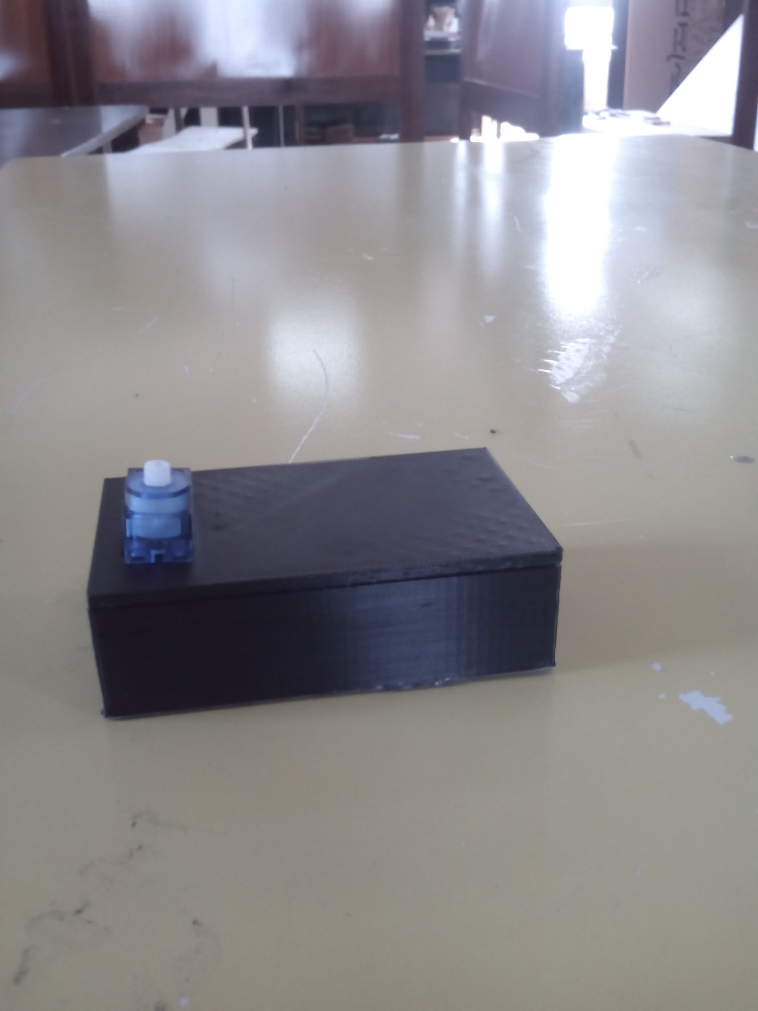
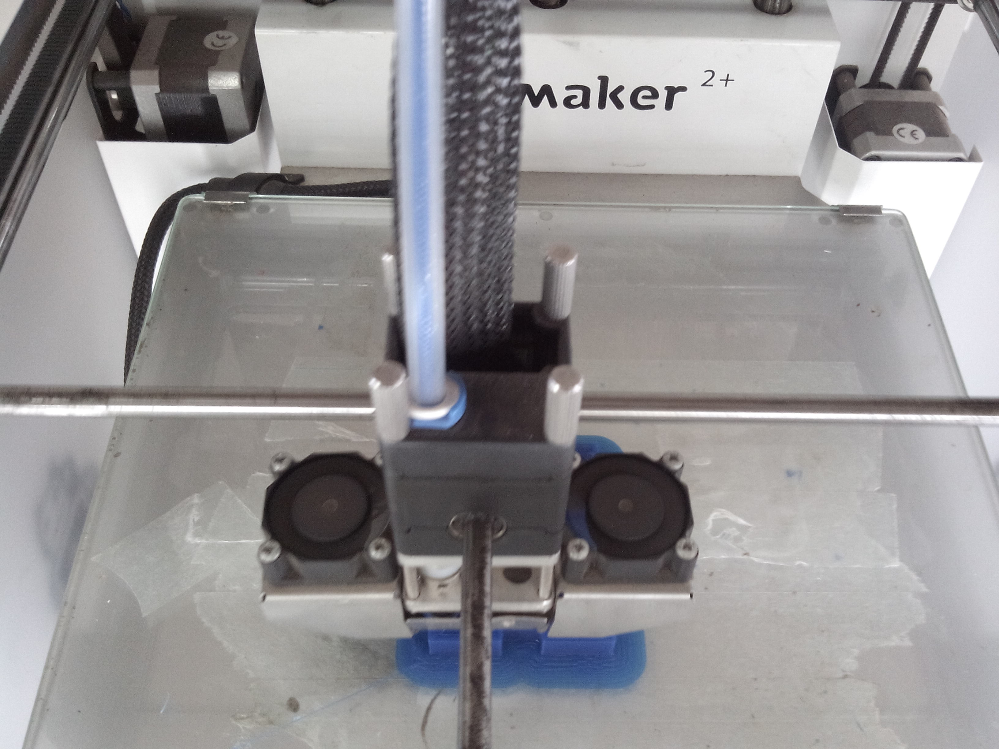
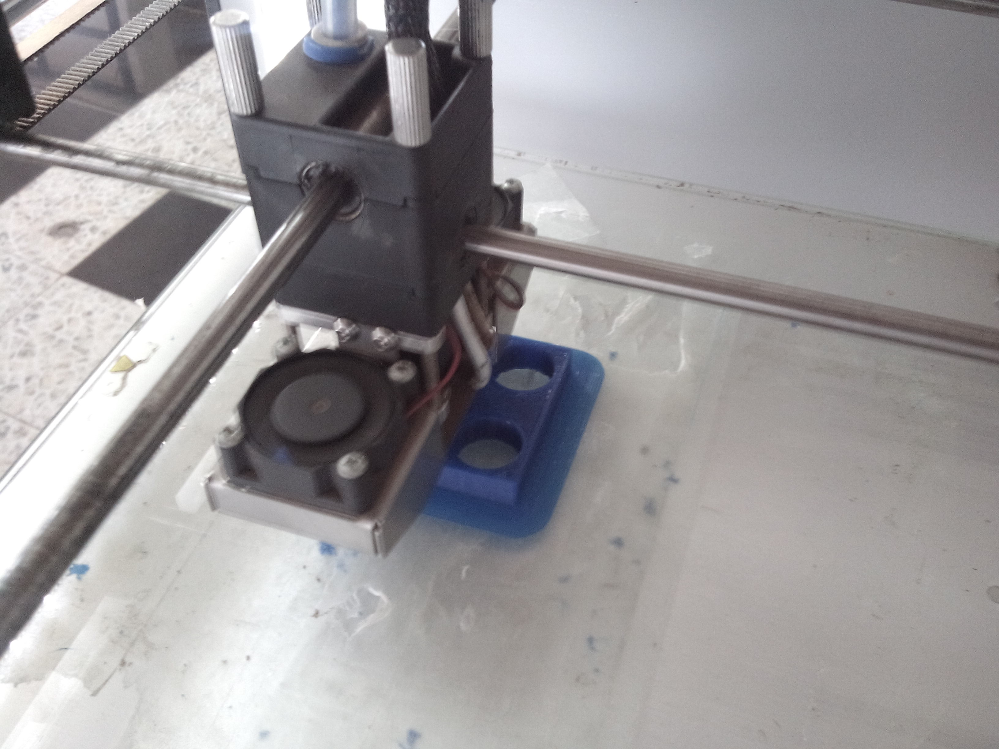
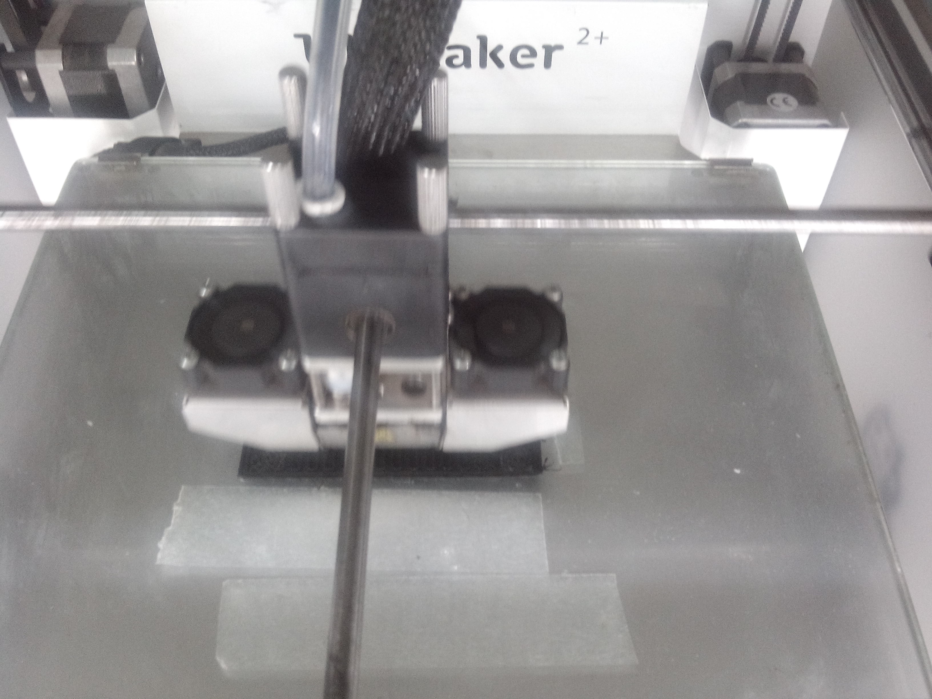
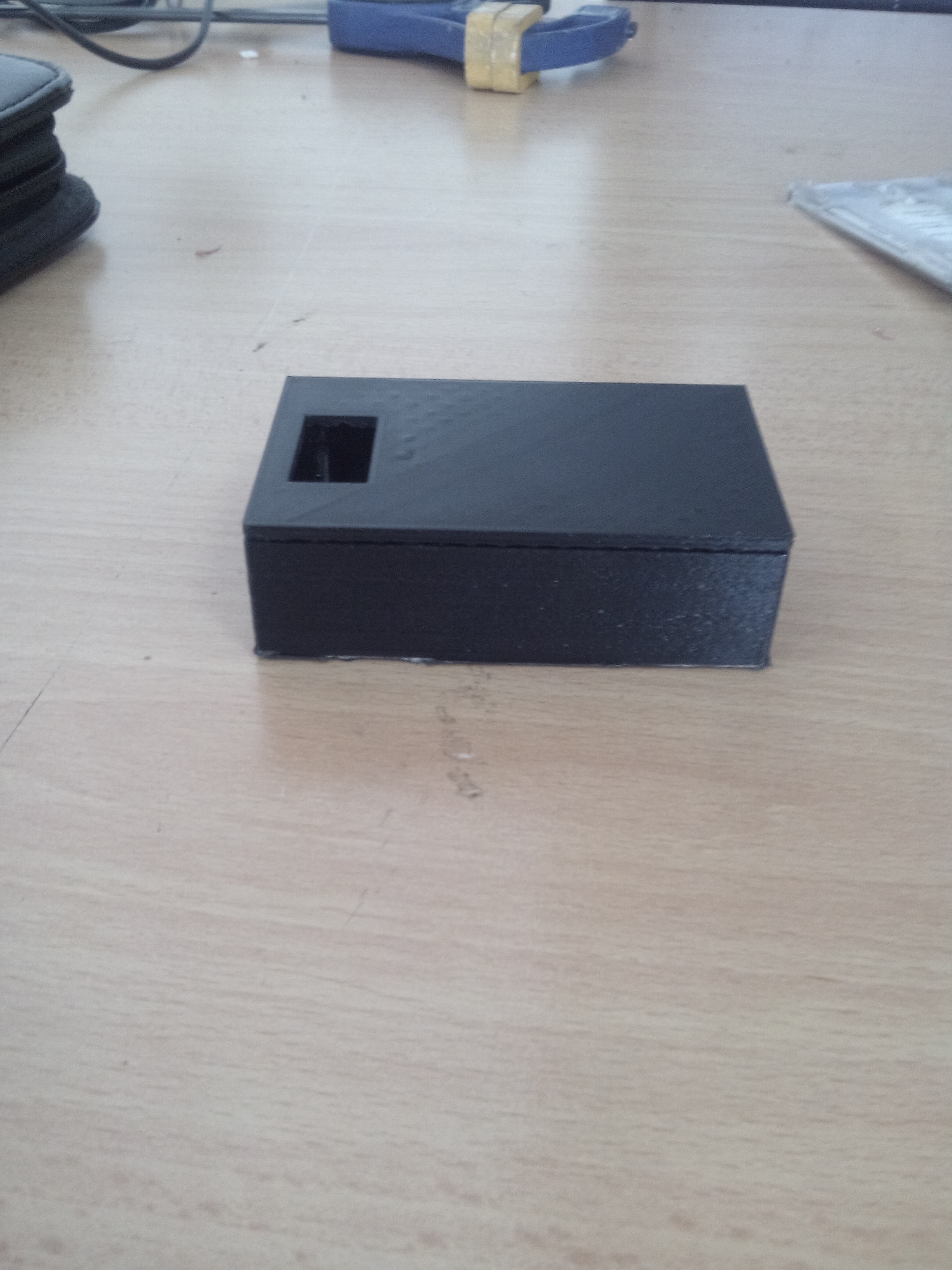
In parts of printing
we print my cover of project by using 3D printer
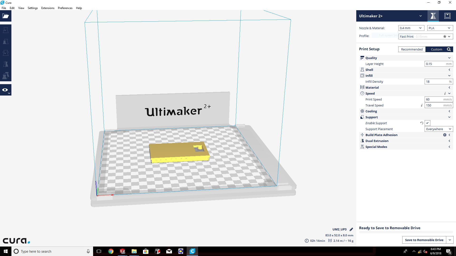
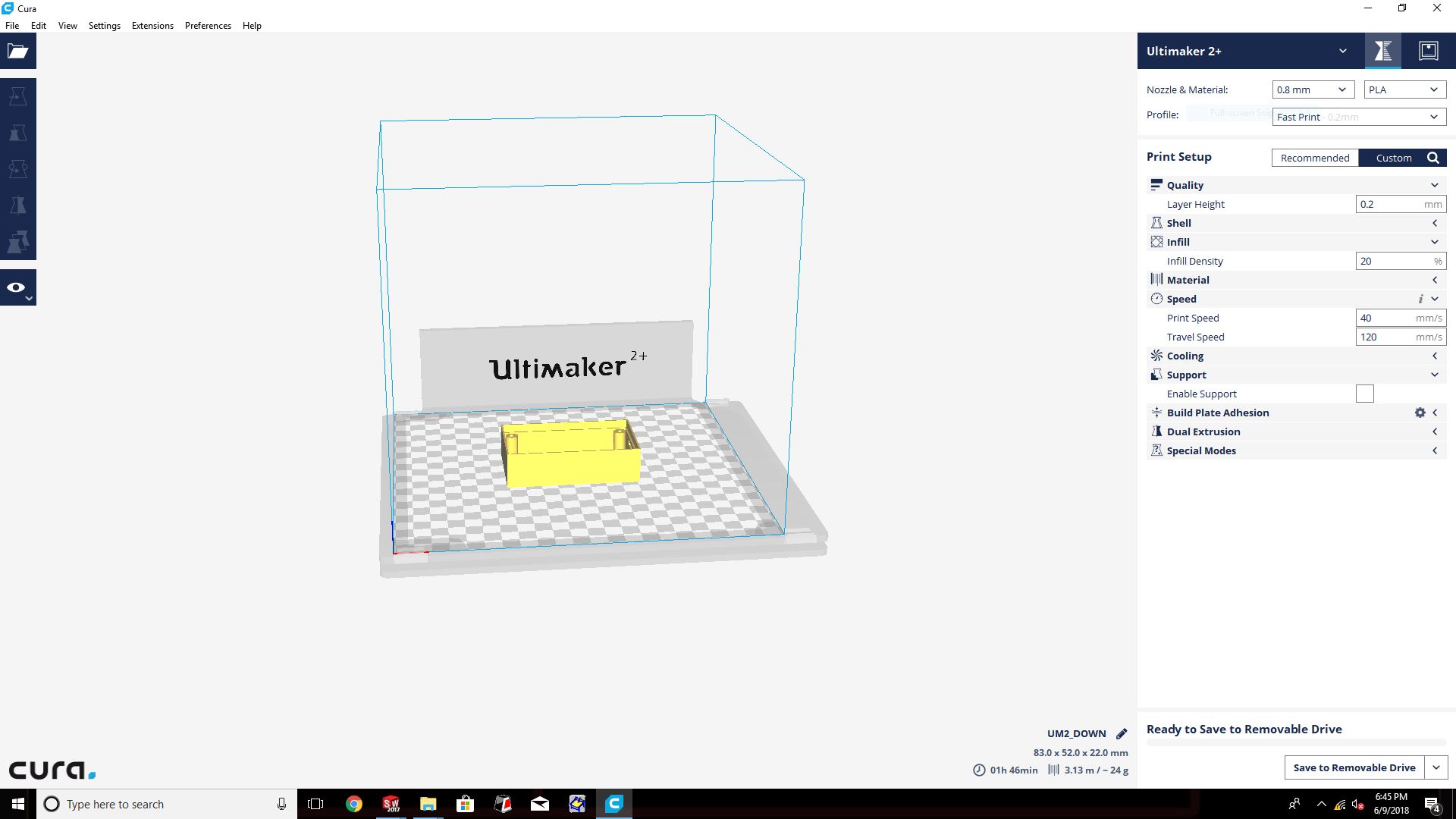
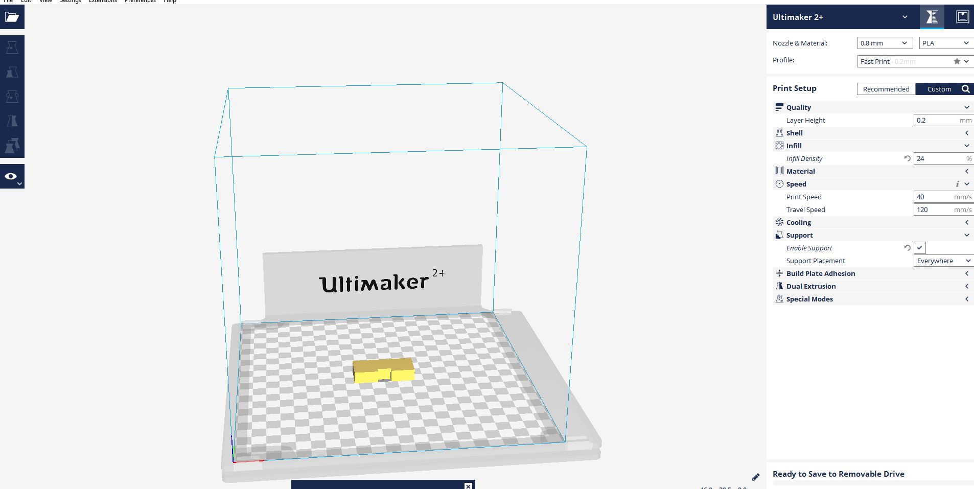
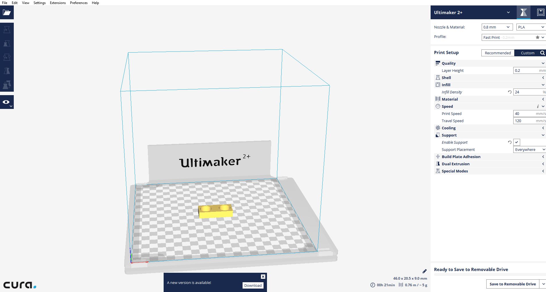
that are 3D print in process of printing
In parts of programming
we can begin in programming of hardware
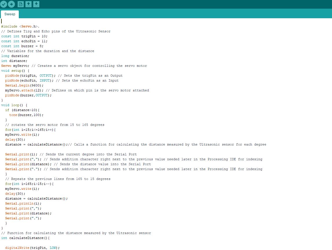
Arduino Source Code with description of each line of the code:
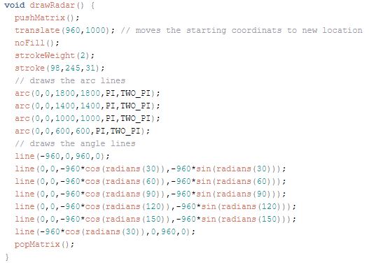
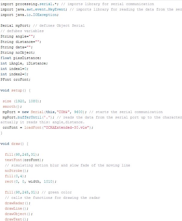
Now we will receive the values for the angle and the distance measured by the sensor from the Arduino Board into the Processing IDE using the SerialEvent() function which reads the data from the Serial Port and we will put the values of the angle and the distance into the variables iAngle and iDistance. These variable will be used for drawing the radar, the lines, the detected objects and some of the text. by using java code.
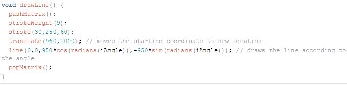
For drawing the line that is moving along the radar I made this function drawLine(). Its center of rotation is set with the translate() function and using the line() function in which the iAngle variable is used the line is redrawn for each degree.
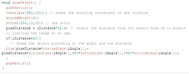
For drawing the detected objects I made this drawObject() function. It gets the distance from ultrasonic sensor, transforms it into pixels and in combination with the angle of the sensor draws the object on the radar.
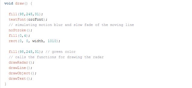
All of these functions are called in the main draw() function which repeats all the time and draws the screen. Also here I am using this fill() function with 2 parameters for simulating motion blur and slow fade of the moving line.
that are the application interface that are created
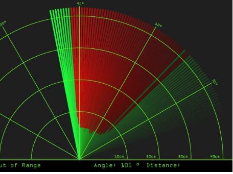
that is the complete Processing Source Code of the Arduino Radar:
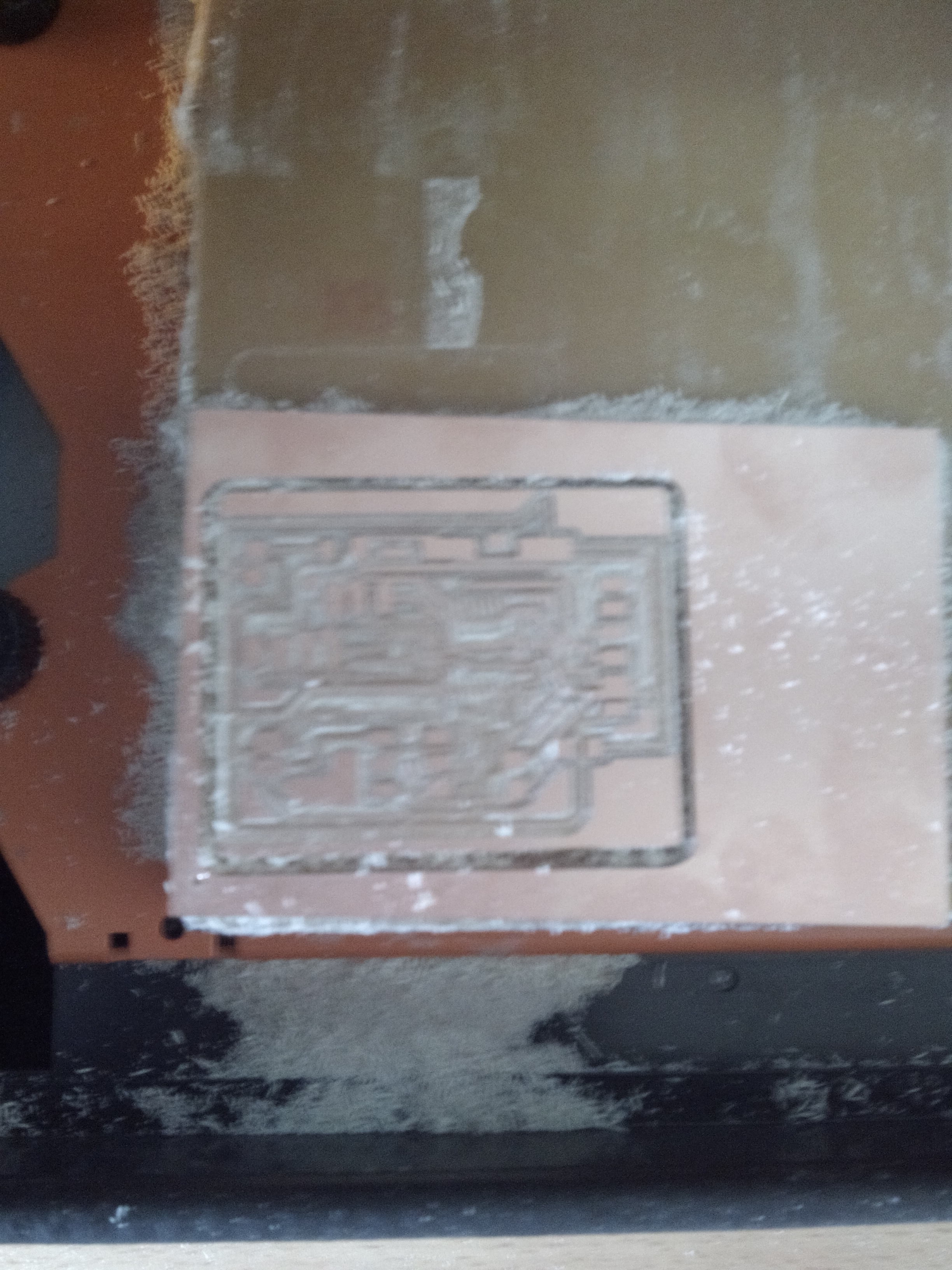
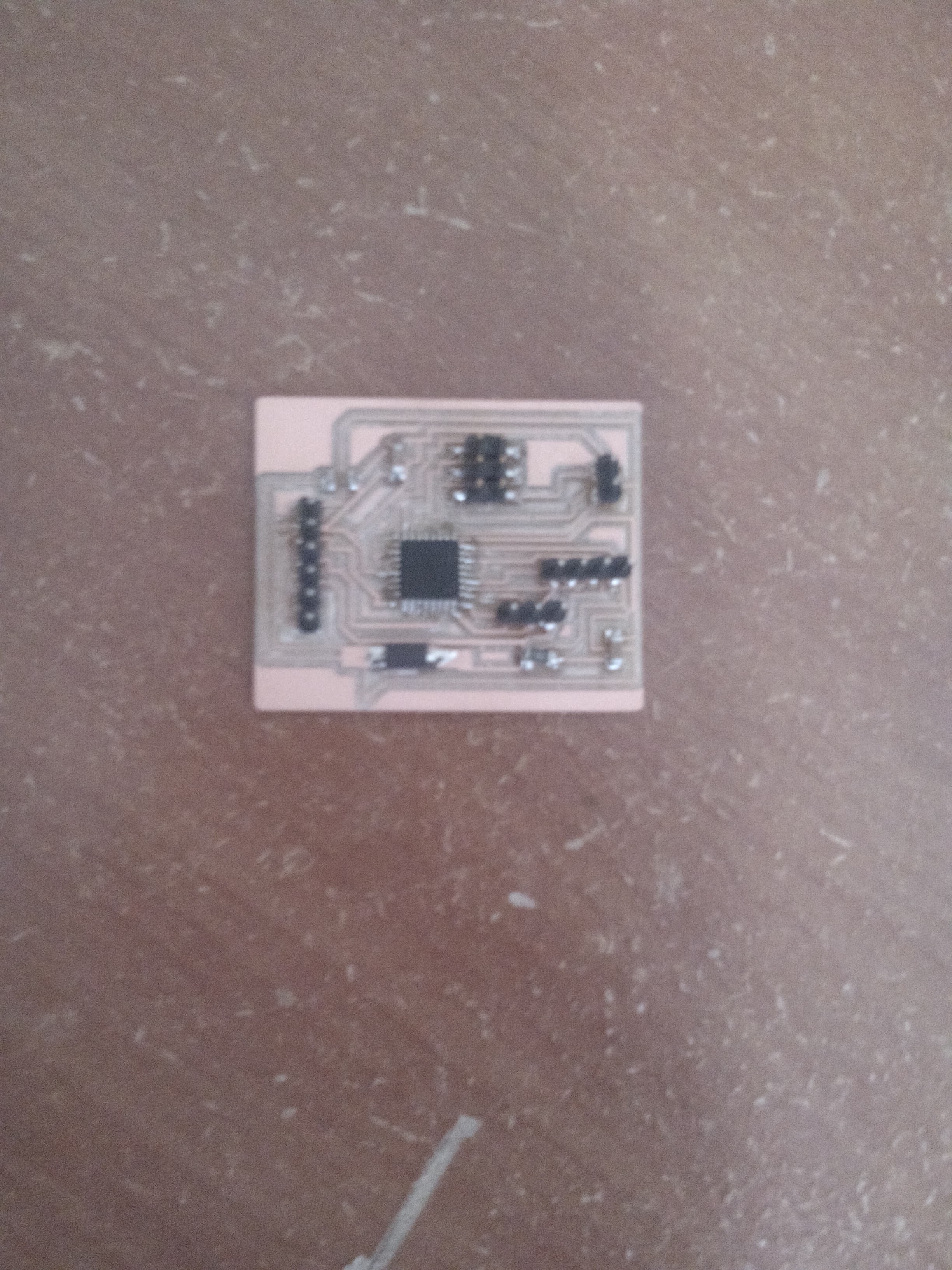
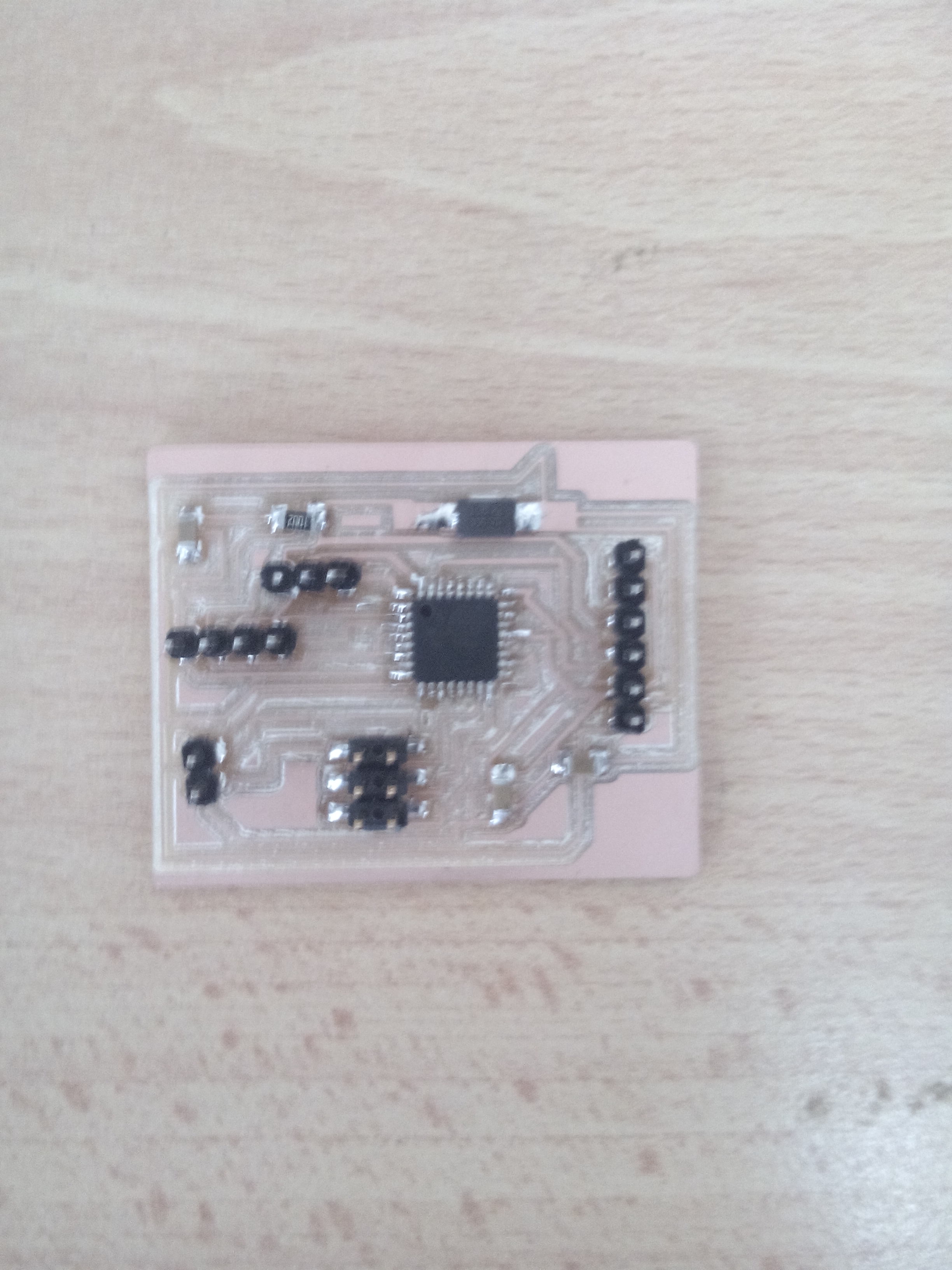
in part of electronics
we can begin to skech in software called eagle
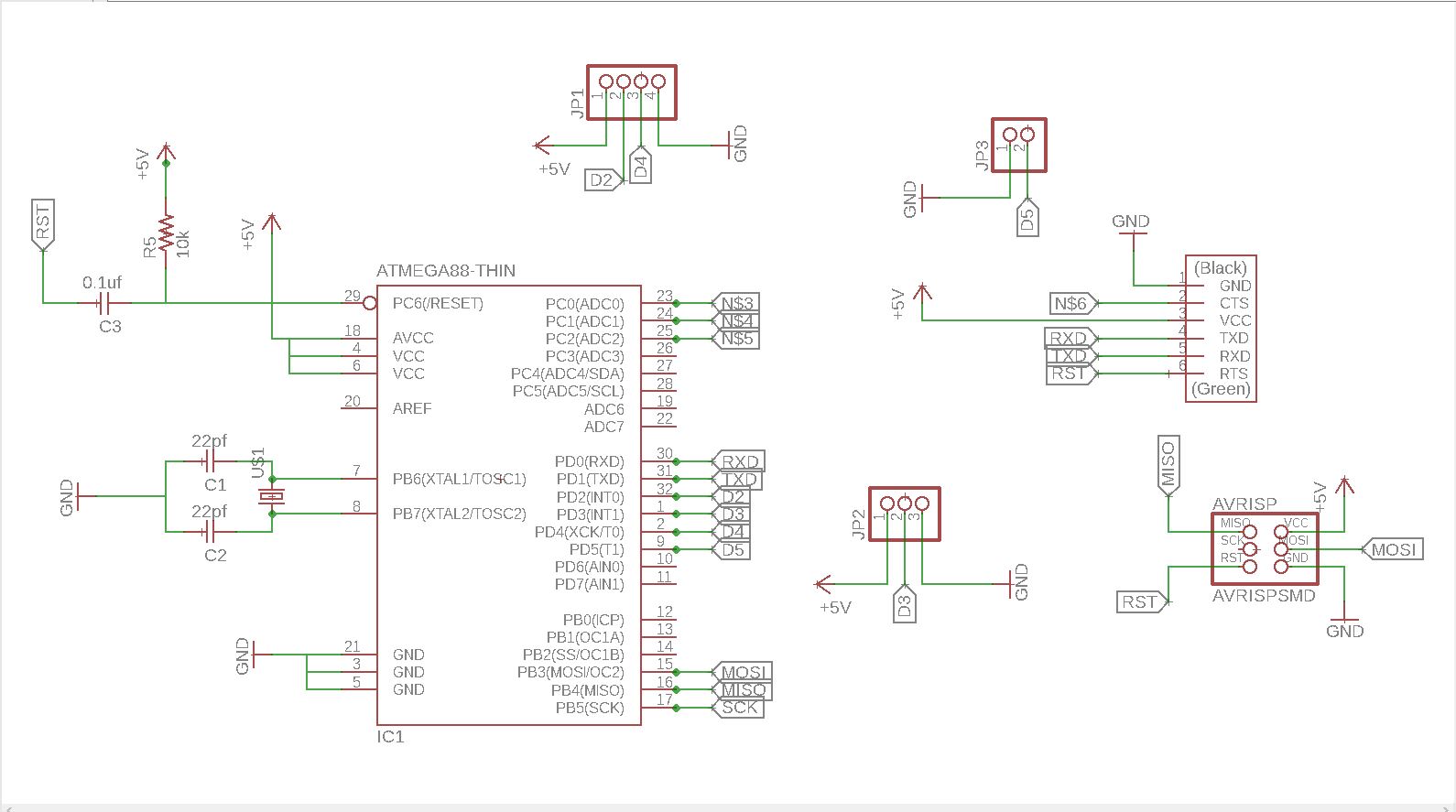
we can convert the schematics that are design in eagle into to board.
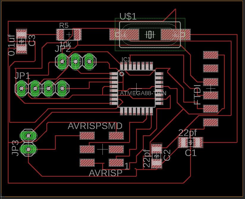
conevert the board into the png in trace.
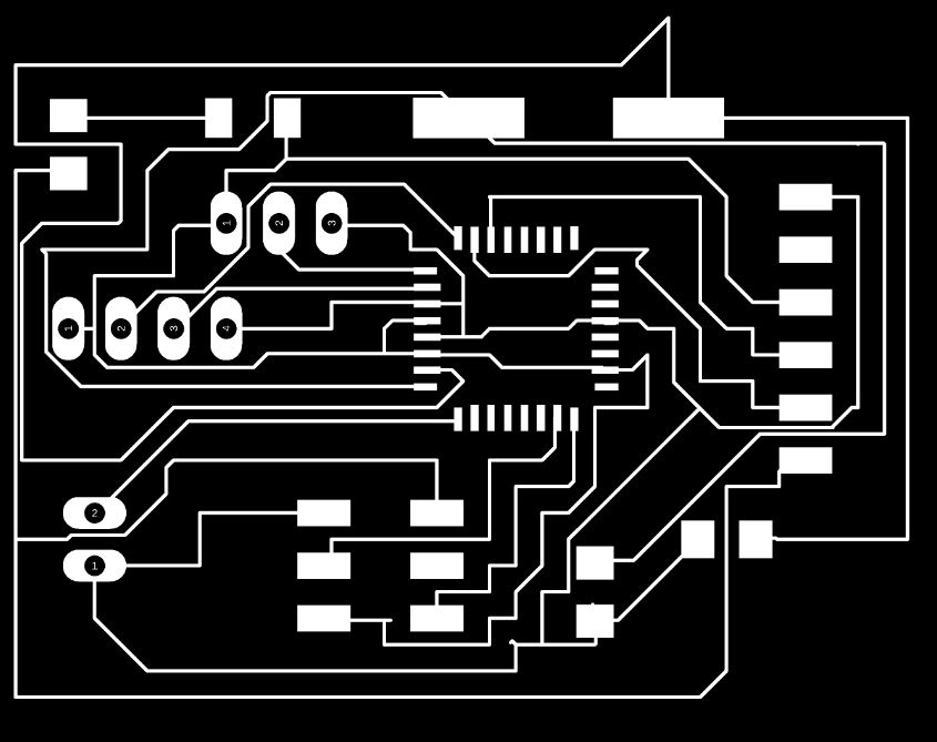
create the png of outline.

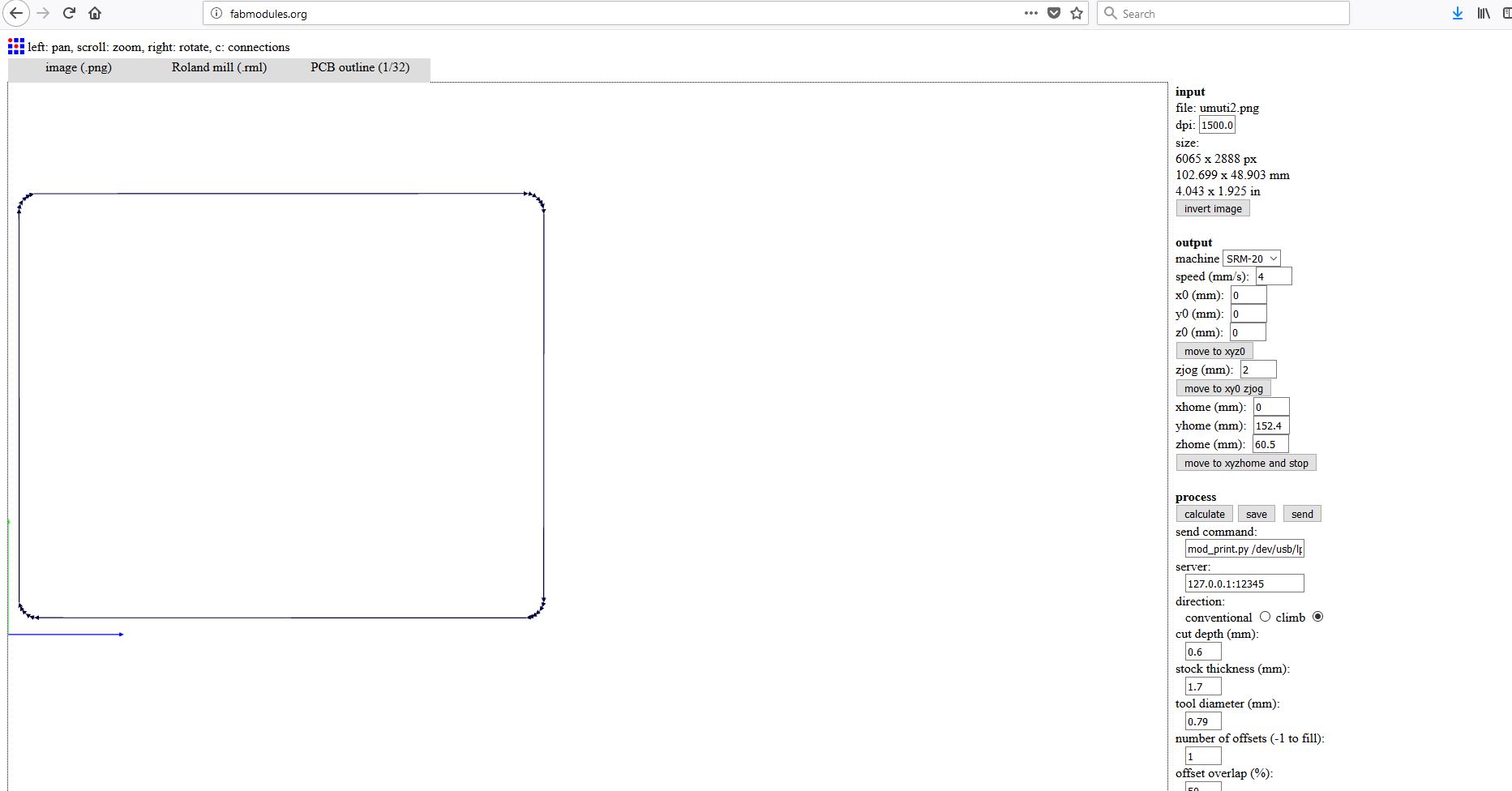
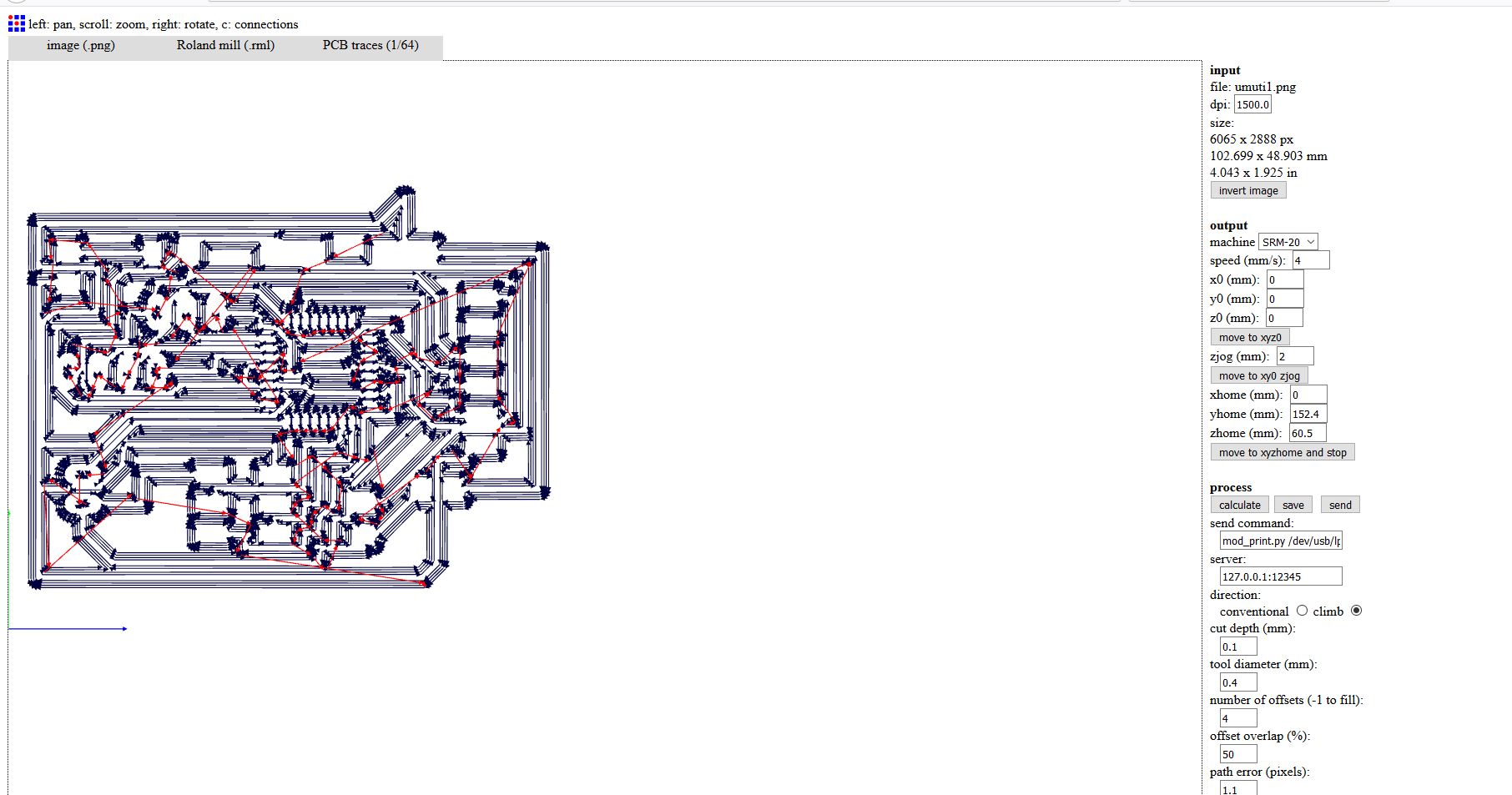
I have first converted my images from .png to .rml since its what the milling machine takes as input. I used fabmodules to convert fabISP images to rml. On Input format drop down I choosed image(.png), on output format I choosed Roland mill(.rml), and on process I choosed PCB traces(1/64). And continued selecting on machine I choosed SRM-20, other settings were made automatically then I clicked on Calculate button for converting it.
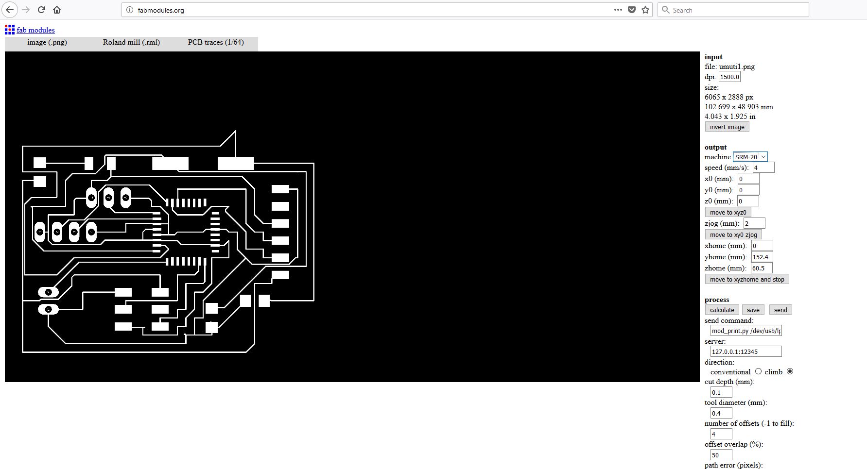
that schematics show some configuration by using fab modules
After calculation done on the image, the rml file is generated .
Now I have done the same thing on the edge cut file with some modification like on process I selected PCB outline(1/32) and on cut depth (mm): I entered 1.6 cause I want to cut through the board. .
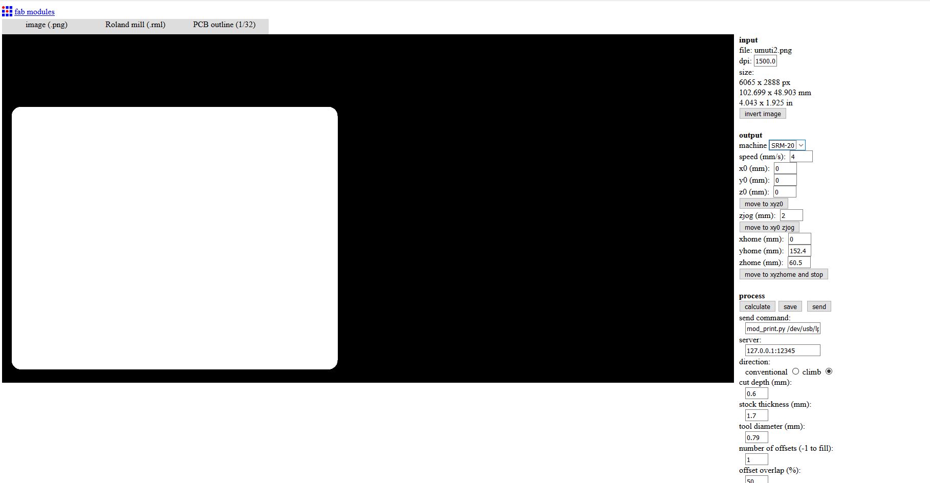
After calculating the path for the tool the RML file is generated.