 |
 |
 |
 |
Week12. Output Devices
group assignment:
measure the power consumption of an output device
individual assignment:
add an output device to a microcontroller board you've designed,
and program it to do something
1. measure the power consumption
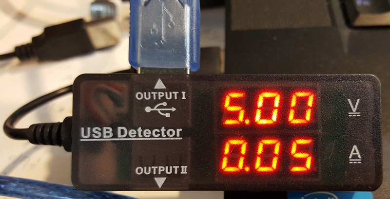
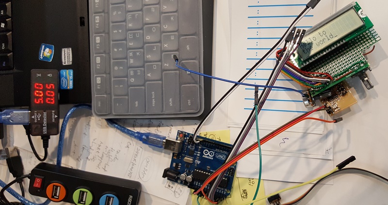
To catch the test value, I used with USB power checker device.
It can be tester for dc voltage and current consumption.
But, It takes more add power used due to plus device(arduino-UNO as power converter)
As show parameter :
- Voltage(V) : 5V
- Current(I) : 0.05A(50mA)
The power = V x I = 5V * 0.05A = 0.25W(Watt) = 250mW
2. Hardware Making and Electrical Test
work process
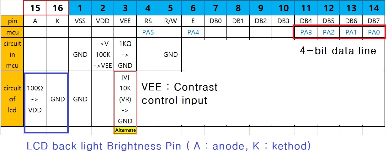
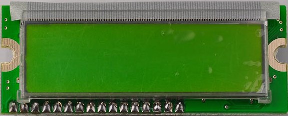
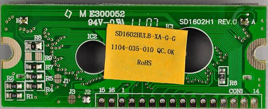
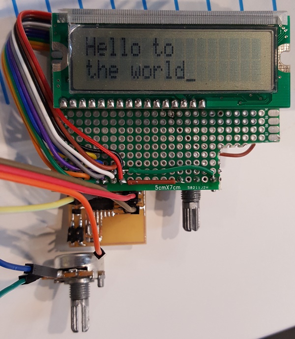
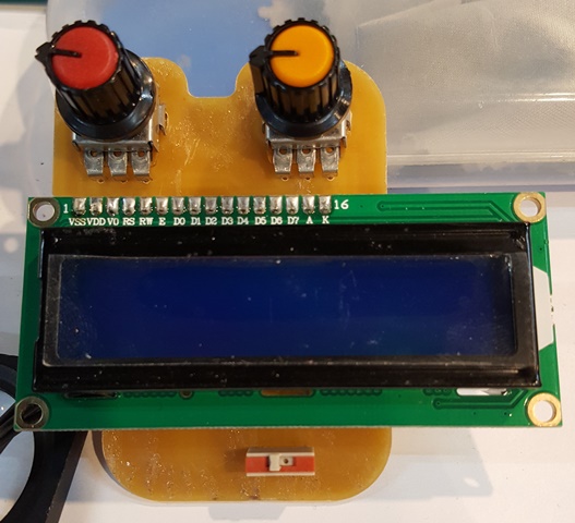
Connect hello.lcd.44 board to LCD(SD1602H1 Rev.0). I did add circuits for backlight brightness and contrast control.
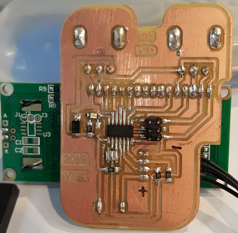
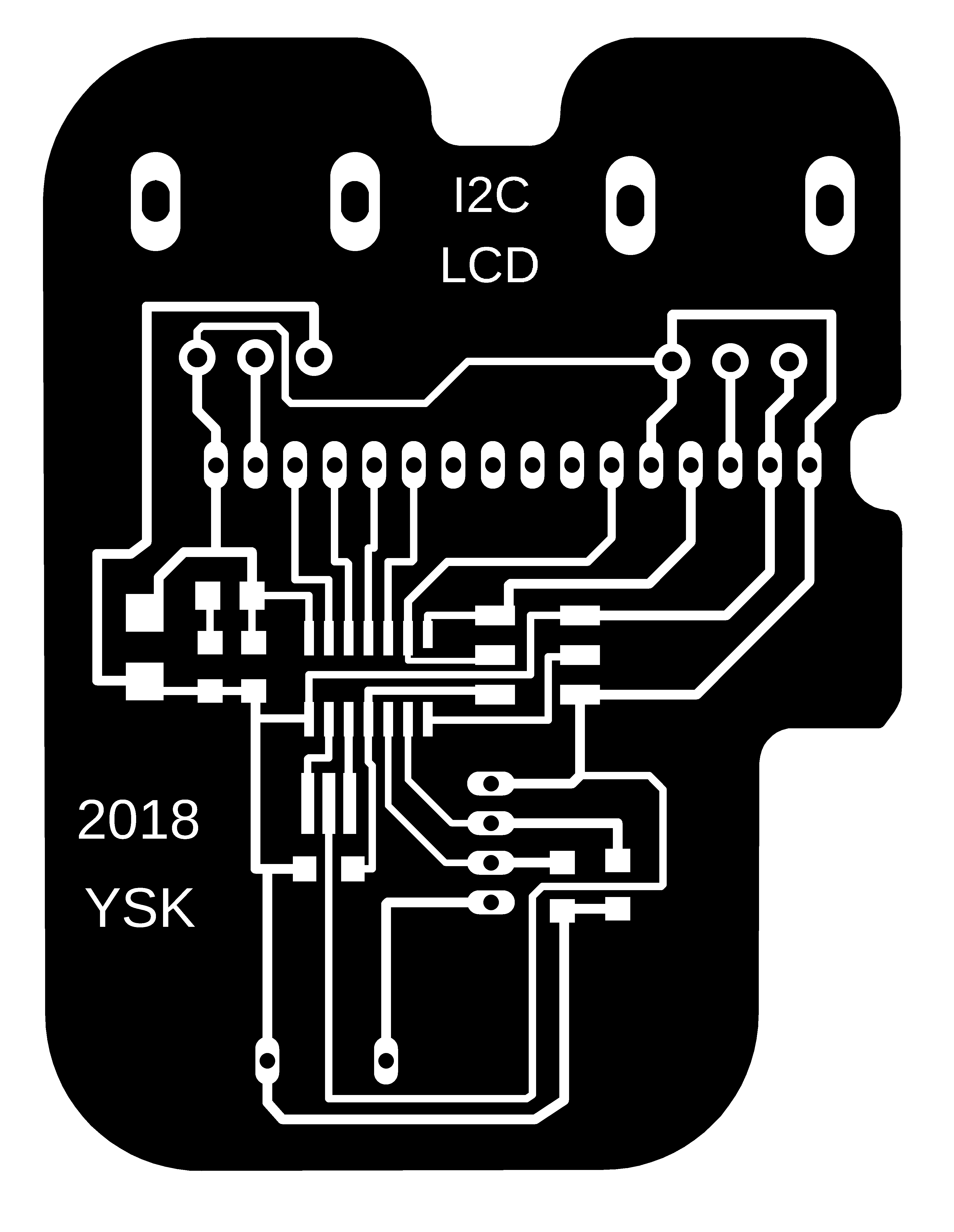
For reusability of LCD, design additional PCB circuits to connect LCD.
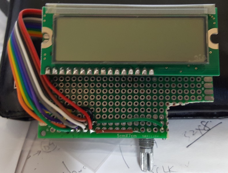
b. Results
At first, input the USB power through the FabISP. There is no back light up when power input.
But, natural contrast image appeared that means just power engageed properly.
c. Conclusion
There are no needs additional contrast circuits. Check about data sheet for backlight connection.
3. Programming and Debugging
a. work process
Create new project in Atmel Studio 7. import hello.lcd.44.c code to main.c. Compile with WinAVR(avr-gcc 4.3.3),
build and upload with FabISP as USBtiny programmer.
b. Results
- 1. Sometimes can't find USBtiny programmer, so I did every time update the usb driver as libusb-win32 (v1.2.6.0)
in 'Zadig.exe' tool.
- 2. After build, missing project.hex(it depends on decision) to upload process sometimes.
- 3. First of all, there are no sign about LCD activity after upload.
c. Conclusion
As a results, I thought about the errors are depends on circuitry so I made a checklist and checked all for
everey each step to fix it.
Step-1. Check about solder state, power input and manual wiring.
-> After resolder, I did open-short test and there was no error points.
Step-2. For check about LCD, I read about LCD datasheet, and I made a sample LCD project with 'arduinoUno'.
-> That was a good working. It has a fine state , also comes characters on screen.
It makes me to inverstigate writing process.
Step-3. Check for writing process correctly.
-> I found a strange activity of AtmelStudio7 for writing, that process must be doing in focuse to 'project properties'
tab. (If the job in doing 'main.c' tab, that will be make an error can't open 'hex' file)
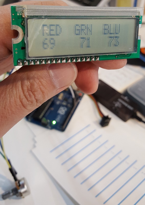
After this, It was still did't characters. Monently, I thought about that LCD can be handled common used
with some ISP pins. It makes mulfunction for operation. So, I did put only +5V and GND pins on V,GND connection.
In that time, I found clear characters to play in LCD.
Step-4. Check in stand alone powered in.
Even complete working, there were some misunderstood error points exist.
It can't show characters on LCD that test in power supply to put the energy to the board.
Step-5. I asked what's wrong to instructor that makes me to understood what was my fault.
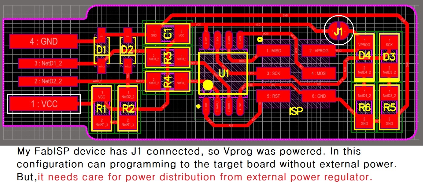
-> It relateded with FabISP's Vprog pin state to write. In my ISP board, there are join VCC with Vprog.
It makes that powered to the target board and writing both(thats convinents).
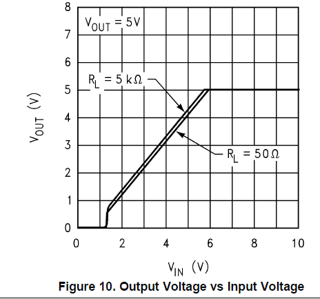
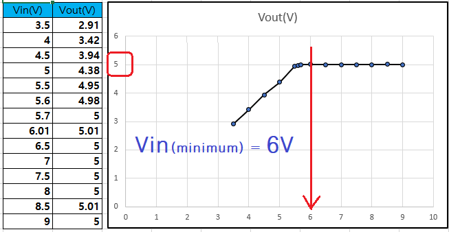
But, It tooks also bad infulence to Vout pin of LM3480 LDO in every writing process.
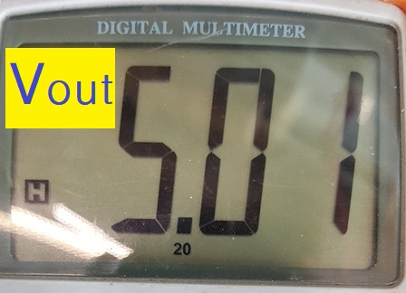
Step-6. Finally, I test and clearly understand with a simple experimants.
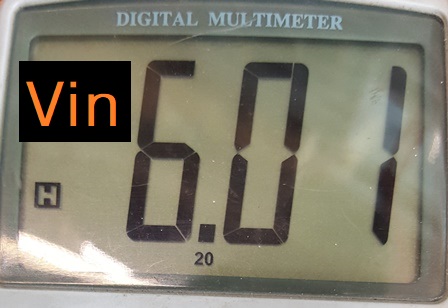
It was make an part of LDO area saperately and check voltage variation with multimeters.
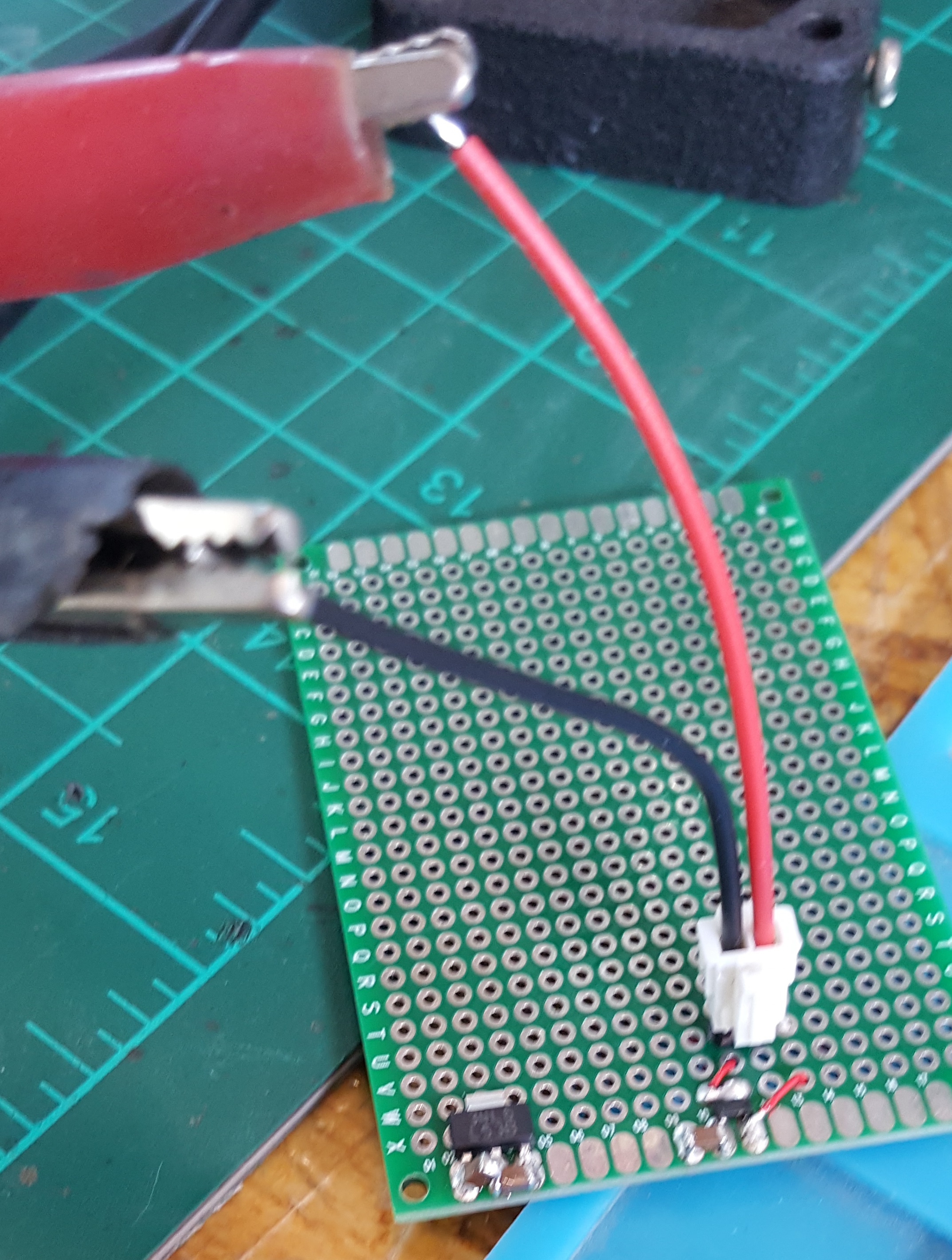
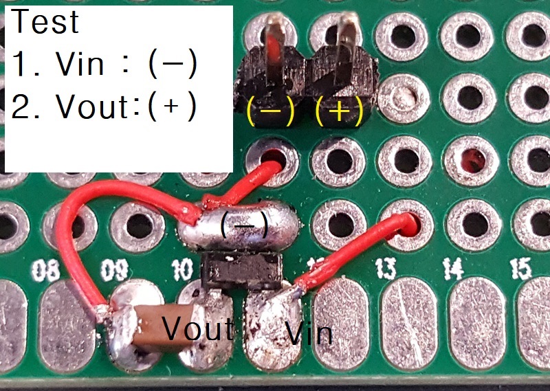
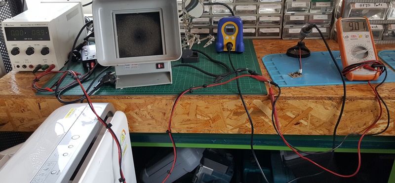
Voltage read:
4. Programming Process about AtmelStudio7 environment
Step-1.File/New/Project
New Project popup windows, GCC C Executable Project,
Name : project1( New Project name)
Location : D:\Atme7Project\fab14_project\ (as your project folder)
Solution : Create new solution (default set)
Solution Name : project1 (same as Name property)
check -> [*]Create directory for solution (for version control)
Click -> [OK] button
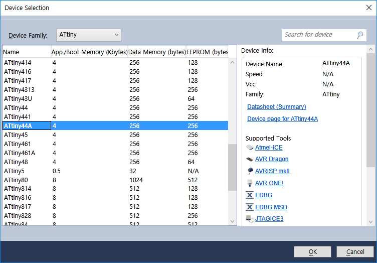
Step-2. Select device
Select correct device in Device Selection pop-up chart
- Device Family: select family category in list box
- select device -> select a device to use in filtered chart
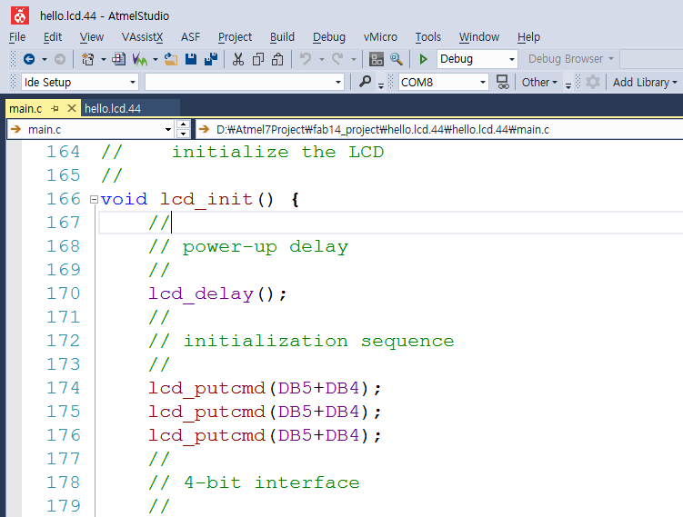
Step-3. Edit code
After select device, show up "main.c" edit window. Make a working code.
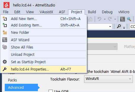
Step-4. Compiler Setting
Go to menubar, select Project/project1 Properties.. [Alt+F7]
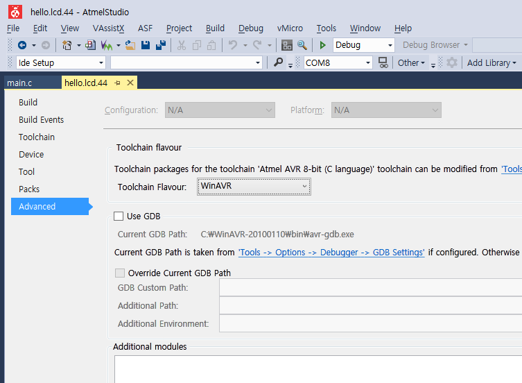
In project1 (Properties)tab, Click Advanced menu lowest left menu, then
change Toolchain Flavour from 'Native' to 'proper compiler(in this project, set to
'WinAVR'[ref1]). If it needs manage old code for develop, can be available
in this option.
*[ref1]:I was pre install 'WinAVR-20100110' compiler to use 'WinAVR' option. I found
prefer to avr-gcc 4.9.2 compiler version for reference code, so first of all,
I desided to follow and check about reference codes, choose that similier version
avr-gcc 4.3.3(WinAVR--20100110).
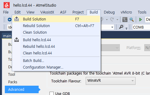
Step-5. Build
If it needs to upload program, At first, to make compile and project1.hex file to
upload. It is important the job must be in project1 properties tab, go to 'Build'
menubar then click to 'Build'[same as F7-press] menu to make whole files in process.
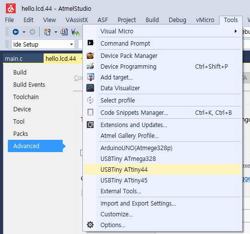
6.Uploading
After build process, go to 'Tools' menu then select pre defined tool
Check about Output record to find any kind errors for uploading process.
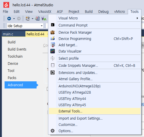
*[ref2] : External Tools
When use custom programmer, [Add] New Programmer to External Tools.. in Tools menubar.
Setting parameters are needs to make as below example.
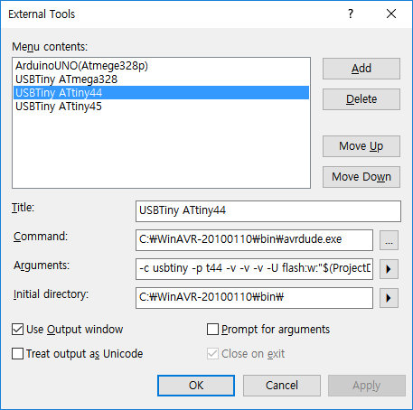
Menu contents : USBTiny ATtiny44
Command: C:\WinAVR-20100110\bin\avrdude.exe
Arguments: -c usbtiny -p t44 -v -v -v -U flash:w:"$(ProjectDir)Debug\$(ItemFileName).hex":i
Initial directory: C:\WinAVR-20100110\bin\
Step-7. Show making files.
here are some records, to find hints what was going on.
Arduino Test output record
Fail to upload output record
Success output record
Download files:
pcb files : traces,
hole data,
interior line
c code : used program from fabacademy
WinAVR link : WinAVR download site
*note: For the first time try, I just use i2c.lcd.44 board on fabacademy. But now I have redesigned the lcd output board.
This is my eagle cad files : schematic file,
PCB board file
-This is my code.
-LCD communication steps in protocols