 |
 |
 |
 |
Week14. Networking and Communications
group assignment:
send a message between two projects
individual assignment:
design and build a wired &/or wireless network connecting at least two processors
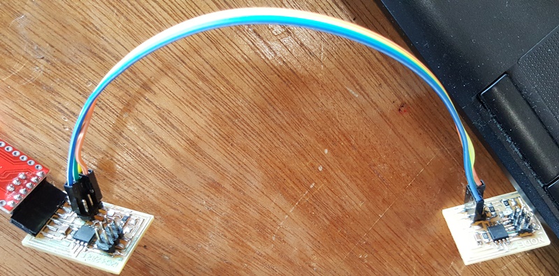
1.design wired network
I did combind hello.bus.45 boards and hello.I2C.45 boards to test with each cases.
Here are all files that I made.
- Design file download(eagle cad format) :
* bridge board : schematic for bridge |
pcb for bridge
* nodes board : schematic for nodes |
pcb for nodes
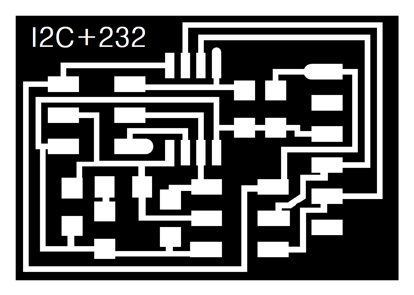
- Bridge board for communication to PC and node boards (png image format) :
trace for bridge |
outline for bridge
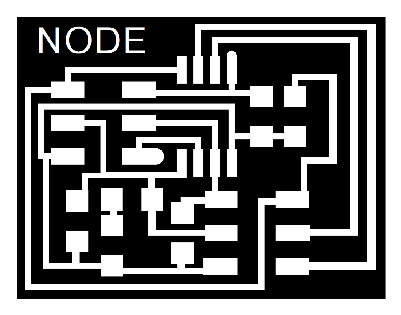
- Node board for communication to PC :
trace for node |
outline for node
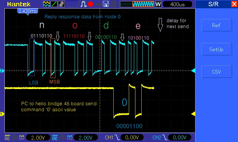
Program operation
1. Send command '0' to call node 0(bridge) '1' to '3' characters as node number call the others.2. If come command correctly, blink LED of all nodes ones and matched node reply characters such as 'node id(number)'
next blink again in pointed node.
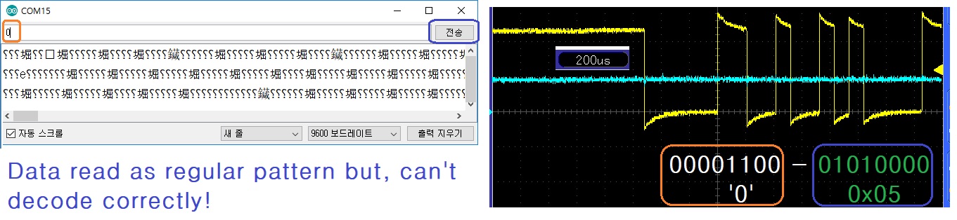
1. Program test
Here is 1st read after compile and downloading.Reference Source Code : bridge code ,
modified source code :bridge and node code
* for node code : change node numbers in bridge code('1','2','3')
Compiler and build environment : WinAVR-20100110 , AtmelStudio7
Result
1. LED blink test : 1st blink is all done, 2nd blink didn't show in all with linked one serial cable.
2. Data transmission test : sendding command process is done, but receive datas can't resolve.
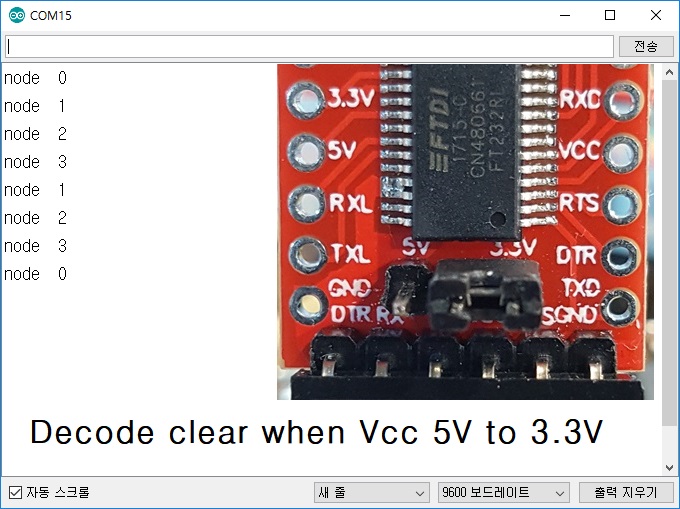
Trouble shooting
In this time, I have got information, if USB to Serial converter's applied Vcc voltage down from 5V to 3.3V
it can be helping with data communication. So I try to change Vcc on converter board.
Here after this step.
- matching action
a. 1st time blink same as code.b. correct reply characters same as code of each node.
c. in bridge board without nodes, can be found 2nd blink.
- unmatching action
a. in 1 node test with bridge board and my 6 pin bus cable, 1st blink can beshow on both but 2nd blink LED brightness a little bit more dark and
still again show of both.
b. in 2 or 3 nodes plus bridge with my cable, all boards show up just one
time blink and all reply correct datas.
- Trial action (* ref.1)
a. There are no change of acting, when I change the node positions.b. after change resistor 1K-ohm to 470-ohm, that symptoms are not change.
c. for the cable test, one node plus bridge with direct jumpper cables connected,
that was correct show as in all sequency of code. That seems to be the
only one thing of problem is cable making!!!
- Conclusion
a. take a good cable and connectors to make cable system.( There are no error found while pin-to-pin test for open-short state
with DMM)
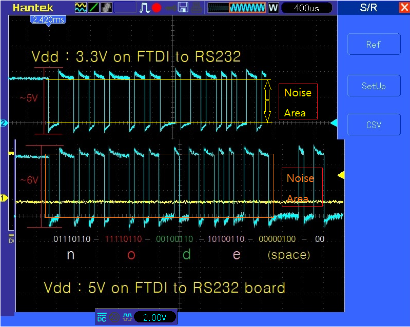
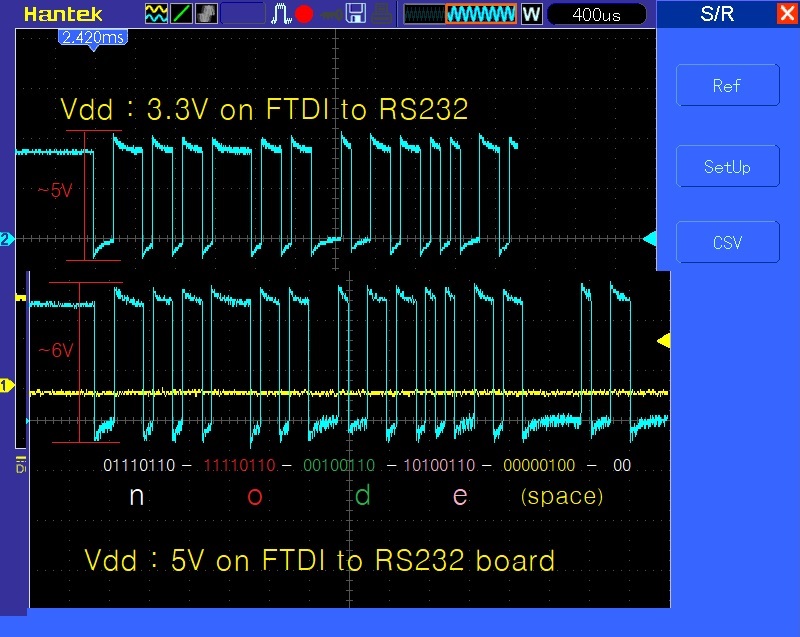
compare between 5V and 3.3V for Vdd FTDI232RL to RS232 converter board.
test video for networking
* ref1. Lesson Learnt
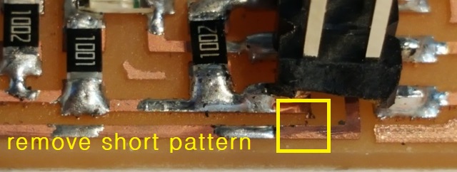
For my project, I just combine an RS232 cable and an I2C cable together. but, I understood about the cable issue( as mention above Trial action)
as only harness problem.
By the way I have some unclear thought about it while doing the experiments about networking between computer through bridge to node 3.
That is my a net harness cable consist of 6 wires(2 wires for I2C), there were still exist same operation about not blink individually.
I just think about that disconnect the wires of I2C, after that, the whole operations matches for wrote as programming.
It means that the I2C's pull-up connections makes the infulence to the RS232 operation.
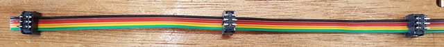
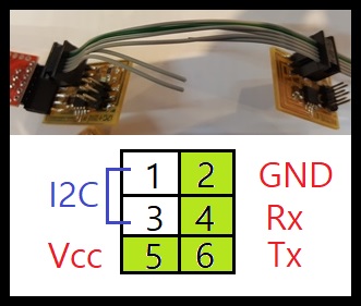
Here is the fixed cable connection for RS232 communication.
* suppliment 1. For the network that I learnt
I needs some technical review of RS232 networking for my application. Basically that was teach me what is the resonwhy not to resolve data transmission. Here I try to explain how I understand about the reson also together how to
implementation for network structure.
Network Topology
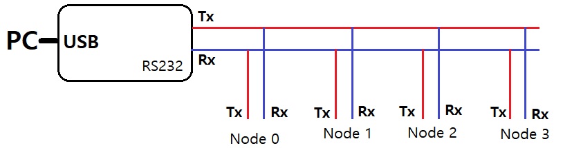
The concepts of communication are at first call to node number as character type variable on Serial terminal then responds
from each nodes
via serial network line. The role of sender(PC terminal) is broadcaster for all nodes and nodes receive
the same commands then compare to own id.
if matching id's node reply 'node' plus delf id number as character type to sender.
The network cable length is with 30cm, its enough to take 3-wire ports
as Tx,Rx and GND also plus Vcc.
Simplfied drawing shown as below. It will be a star topology.
About Network Data foramt
For the network I choose RS232 methods, that works with a serial bit stream as below consist of three parts.
First is start bit second follow to data bits start with LSB(Lowest Significant Bit-refer to B0 in this aticle) and
third are possible configuration of parity and stop bit.
more description
- start bit : It can be teach to receiver to asynhcronize with data bits when it come in to receiver can make own clock to sync data bits.
- data bits : After start bit, these bits followed. And data types are can be selectable 7 or 8 bits.(if the data is filled of only
characters
7bit type will make speed up for transmission)
-parity and stop bit : Parity will help to check tranmission error, basically one bit to teach bit sum result as count the
whole data bits and result number is even set to 0 or odd set to 1. In the short length of distance, Its hardly to find these error but for long distance
communication make sure the put some more solution such as CRC.
Stop bit means that the opposite concept of start bit, ie it will make more time delay to make start bit generation.
Here are a set of general parameter configuration for the short length and low speeds communication,eventhough RS232 is a kind of asynhcronous communication
methods, it needs to define same boadrate both of sender and receiver.
- Baudrate : 9600 bps(bits per seconds)
- Data bits : 8 bit
- Parity bit : None
- Stop bits : 1
- Flow control : None
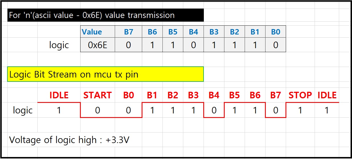
About the Vcc change issue
I recognize the logic voltage level meaning while reads the article of RS232 communications.If the input voltage range set to 0V to +5V(ttl level) then logic 0 voltage must be smaller then 0V and logic 1 voltage
must be above of +5V. The voltage range means that noise filtering area while communication.
Let's find the situation go back to 'conclusion' in Troubleshooting section.
This is again show the Oscilloscope screen and check about voltage level.
I found the shape of 5V logic lines slightly goes inside to the voltage range thats probably make some wrong data to send.
Beside of 5V shape, 3V input logic line shape obiously exist in outside of voltage area. It makes more clear data on the communication lines.