Networking & Communication
Things to do:
2) Send a message between two projects (group assignment)
Have I achieved this week's goals?
Serial communication
Do I really know how serial communication works? Not at all! During the previous weeks I well understood what is a serial protocol but I didn't analyze it deeply. This week was the right time to find out something new about it. In order to study properly, I started looking on the Internet, where I found a good explanation on Wikipedia. In addition, I studied the serial buses and I understood the main difference between the serial protocol and the parallel one.
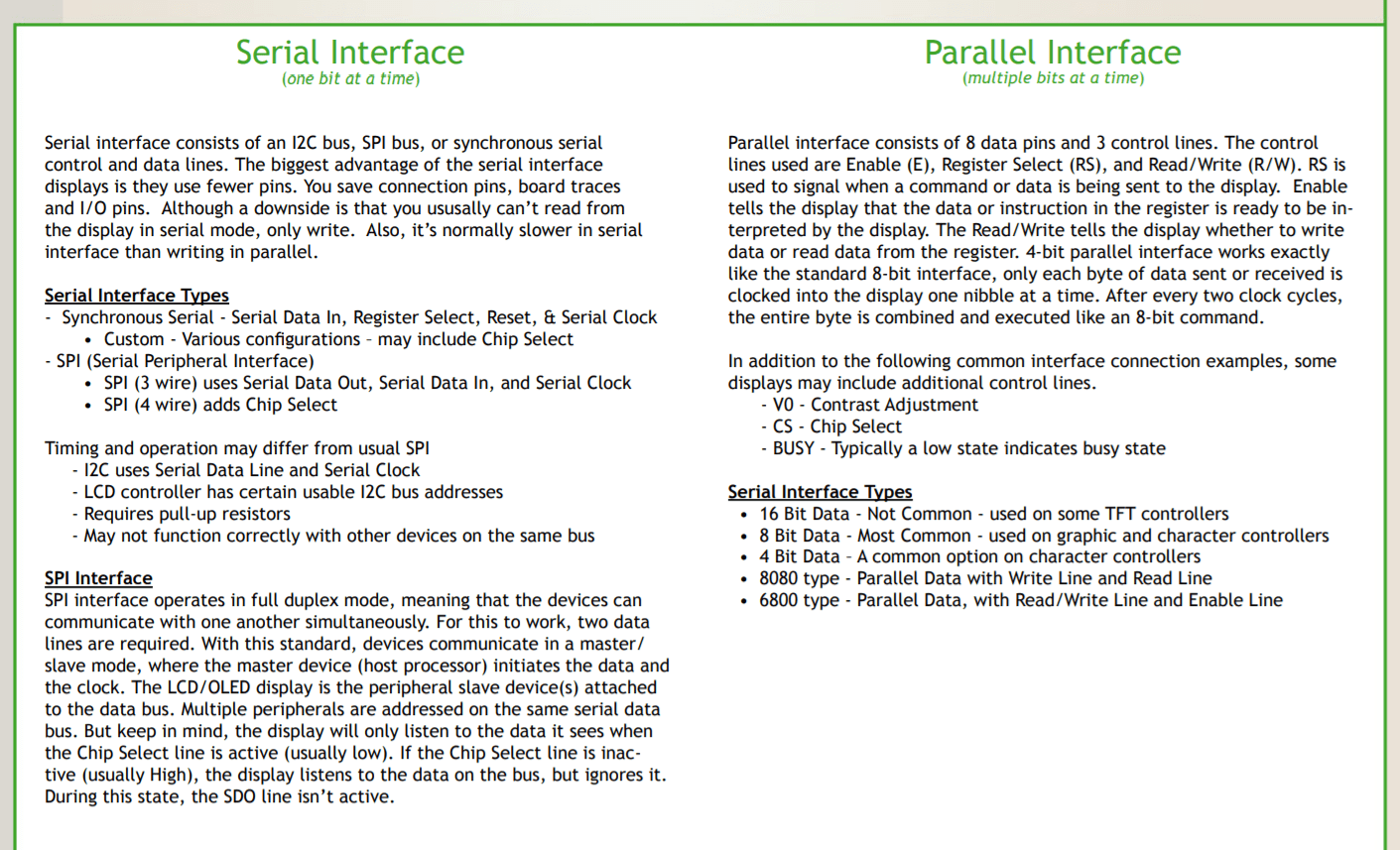
"Serial communication is the process of sending data one bit at a time, sequentially, over a communication channel or computer bus. This is in contrast to parallel communication, where several bits are sent as a whole, on a link with several parallel channels. Many communication systems were generally designed to connect two integrated circuits on the same printed circuit board, connected by signal traces on that board (rather than external cables)."
"Integrated circuits are more expensive when they have more pins. To reduce the number of pins in a package, many ICs use a serial bus to transfer data when speed is not important. Some examples of such low-cost serial buses include SPI, I2C, DC-BUS, UNI/O, and 1-Wire.
Thanks to a useful scheme, it was easy to understand how they work and which are the differences.
I2C protocol
After having studied the SPI protocol, I wanted try the I2C one. Honestly, the 17th chapter of "Make AVR Programming" has been very helpful (even if I hated it during other weeks) and I found many important concepts.
The I2C protocol involves using two lines to send and receive data: a serial clock pin (SCL) that the master board pulses at regular interval, and a serial data pin (SDA) over which data is sentbetween the two devices.
After having found the useful explanation mentioned above, I also paid attention to the I2C hardware level and I found the example below:
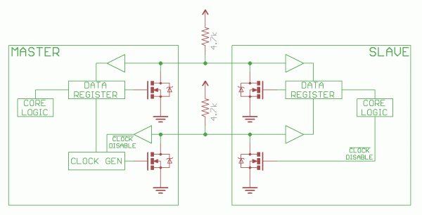
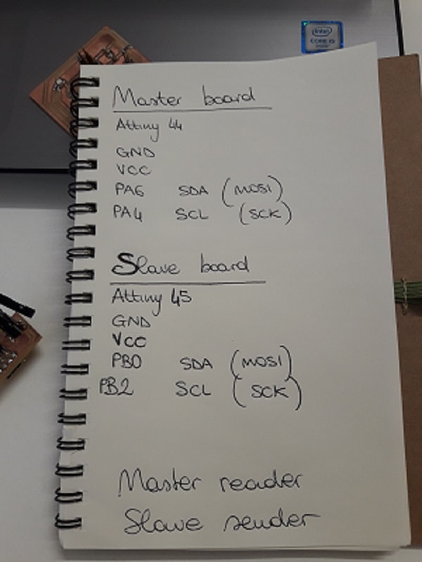
During this week, I decided to use two boards I designed during the previous ones and I wanted to have my hello board as a master and an other one as slave. First of all, I noticed there were four different options and I thought it was necessary to decide which one use before writing the codes.In my case, I decided to have a master reader and a slave sender. So, my master code will control the SCL (serial clock) but it will receive data from the slave.
May be four potential modes of operation for a given bus device, although most devices only use a single role and its two modes:
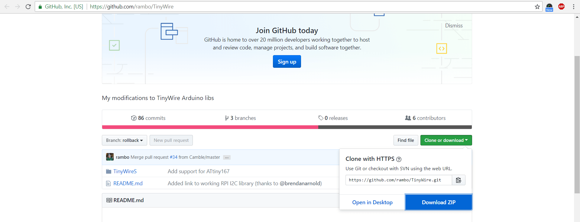
Before starting writing my codes, I installed the libraries on Arduino IDE. The needed library was the TinyWire, which is the same as the Wires one but it works on the ATtiny microcontrollers. Considering the fact I had to use a master and a slave, I needed two differenct libraries: TinyWireM for master board and TinyWireS for the slave one. The first library it can be installed directly via Arduino IDE. The second, is not included in the available libraries, so I went on GitHub and I looked for it. I dowloaded the zip file and I saved it inside the Arduino folder. Then, I opened again the IDE and I imported it clicking on Sketch ---> library settings ---> TinyWireS (you probably find it at the bottom of the drop-down menu. After that, I started writing two simple codes: one for the master and the other one for the slave.
Here there's the master code (in my case it will read the information sent by the slave). So, the master controls the clock (external clock: 20MHz) and receives data from the slave board. In order to program my master board, I set the following options: I had ATtiny44 and external clock 20mHz. After having verified the code, I uploaded it with a programmer board.
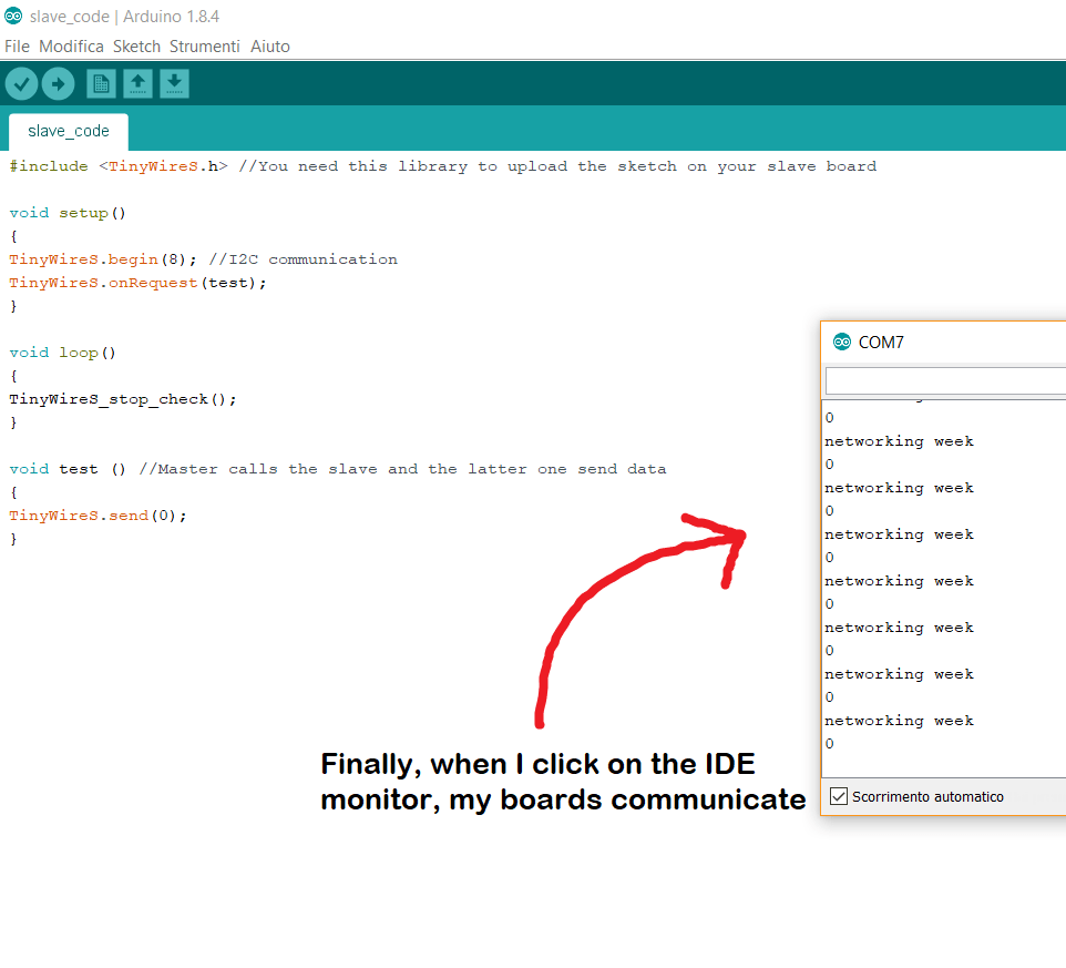
Then, I did the same thing with my slave board. Since I have decided to use it as a sender, I gave it the following commands inside the code. Obviously I changed the library (the one I downloaded as a zip file before). I changed the settings related the microcontroller, because my slave board has an Attiny45. So, I set the following ones: ATtiny45 and internal clock 8Mhz (datasheet here!) Then I verified the code this time too and I uploaded it on my slave board.
After that, I opened both ATtiny datasheets again, because I needed to see which where the pinouts related to the SDA and SCL.
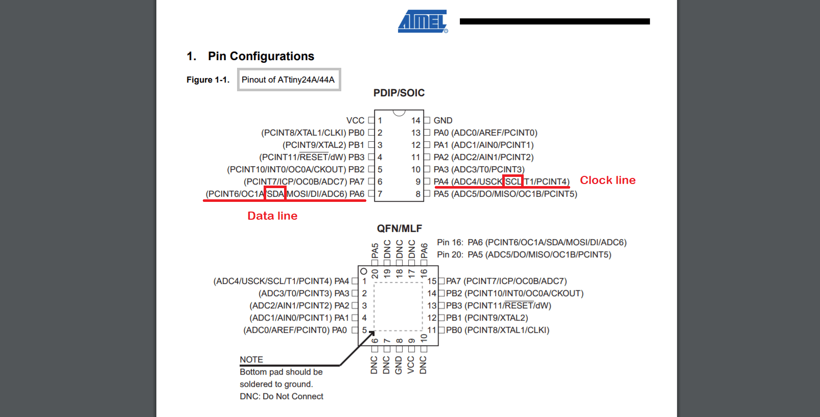
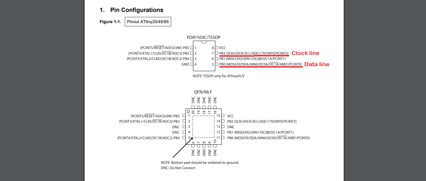
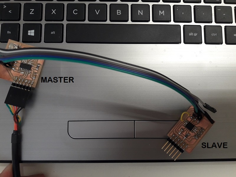
I took some notes, I linked my master board to the FTDI cable and I started linking the ISP pins with the female jumper cables (four wires: VCC, GND, SCL, SDA).
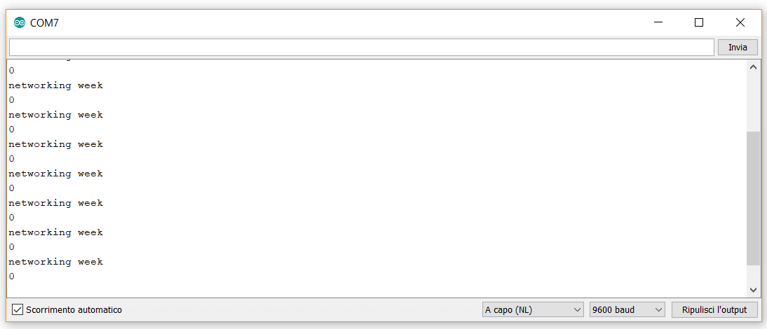
After that, I opened the Arduino IDE and I clicked on monitor view. I saw my two boards communicating one to another :) It has been a good result for me, because this week I studied really hard and even if I wrote two simple codes, I was happy about my first result in this field. Let's see how they work.
Bluetooth module
After this first experiment, I would like to know more about Bluetooth connection. It will be a main part for my final project, so I want to define that as better as I can. Before starting, I understood a man difference between the HC-05 and the HC-06 modules. Only the first one can works as master and slave. Anyway, considering the fact I hadn't previous knowledge on this field, this part requires me more time. I started watching some tutorials on YouTube and then I paid attention in reading how the device terminal functions work. I haven't heard their names yet. So, I googled each name to understand its meaning. I seems like when children ask "why?" for everything.
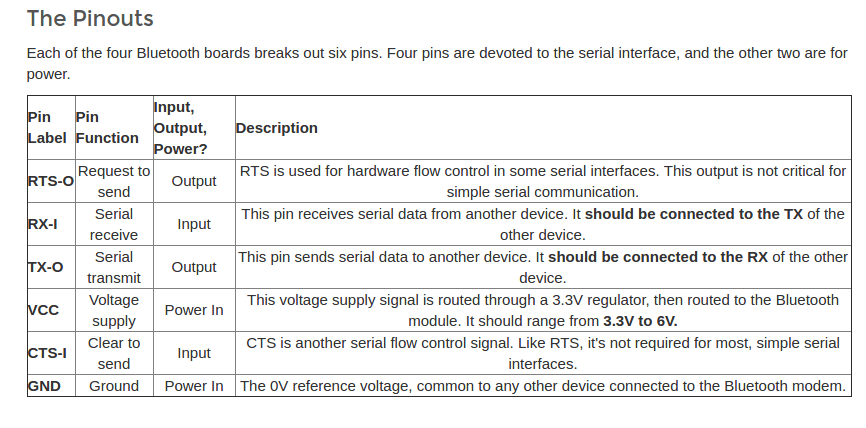
First of all, I noticed that Bluetooth boards break out 6 pins but only 4 of them are related to the serial interface. Let's have a look at the scheme below!
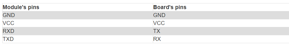
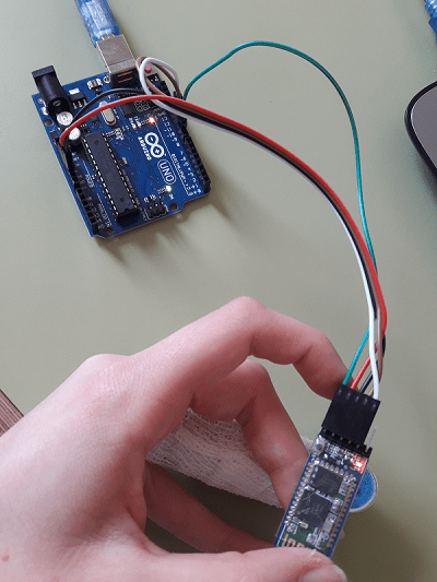
I thought Bluetooth module was easy to be used but...I got wrong! Basically you have to pay attention in inverting Rx and Tx pins, otherwise the communication doesn't work. Considering the fact I did my basic approach with an Arduino UNO, I already connected the wires in the following way:
 >
>
After that (or better...before starting), a vital action in required: understanding how the AT commands work. In order to do a good practice, I'm still trying to clarify which are the main steps to follow and why they work in that way. So, getting to the point...I'd like to improve my knowledge in this area and test the Bluetooth module. I must do that because it will represent an essential part of my final project.
Conclusion
It has been a demanding week but the weekly assignmets reserved me small satisfactions. Even if I have obtained easy results at the experts' sight, I may say I studied a lot and I reached the basic solutions I wanted. I'm aware I have to improve and build more complex solutions, but this week helped me a lot in order to understand networking and communication kernels. Bluetooth configuration is still not clear and I will work on it in order to understand it better. I didn't understand why is so complex configuring the role via the AT COMMANDS. More than this, I have to understand how can I connect two Bluetooth modules. How can they communicate one to each other? I don't know yet! I'm only aware the ADDR command is one of the needed thing. I'll surely update this section with the concerned information.
Update 31st May 2018:
In order to focus my attention on final project, I had a score to settle with HC-05 Bluetooth module. So, I looked for the information I needed. My first aim was to configure it with a ready-made code to upload on it and only then, modify the needed parameters (name, master or slave) via AT commands. First of all, I linked the wired cables to VVC (5V), GND. Then, considering the fact, I'm going to use the Software Serial I connected TX and RX pins to two Arduino UNO digital pins (respectively to pin 10 and pin 11). Moreover, thanks to a tutorial I undestood that I had to connect a fifth wire: the EN (Bluetooth pin) needed to be linked to another digital pin (in my case was pin 9). After having checked the wires connection. My Arduino UNO and the HC-05 Bluetooth module were connected to my laptop, but before starting I disconnected them and I kept the bluetooth module's button pressed. Only after this action, I re-connected the Arduino UNO board to my computer. Fortunately that was the right way to follow: I already noticed that the red light delay was changed. Getting to the point, the red led had a 2-second delay on the module and it meant the AT command was ready to work properly. In fact, I uploaded the sketch and after having verified it, I opened the Serial Monitor and I received the default command: ENTER AT COMMANDS. I quick checked if the values on the serial monitor were correct or not: 9600 baud rate and Both (NL & CR)both were set, so I could start writing AT commands.
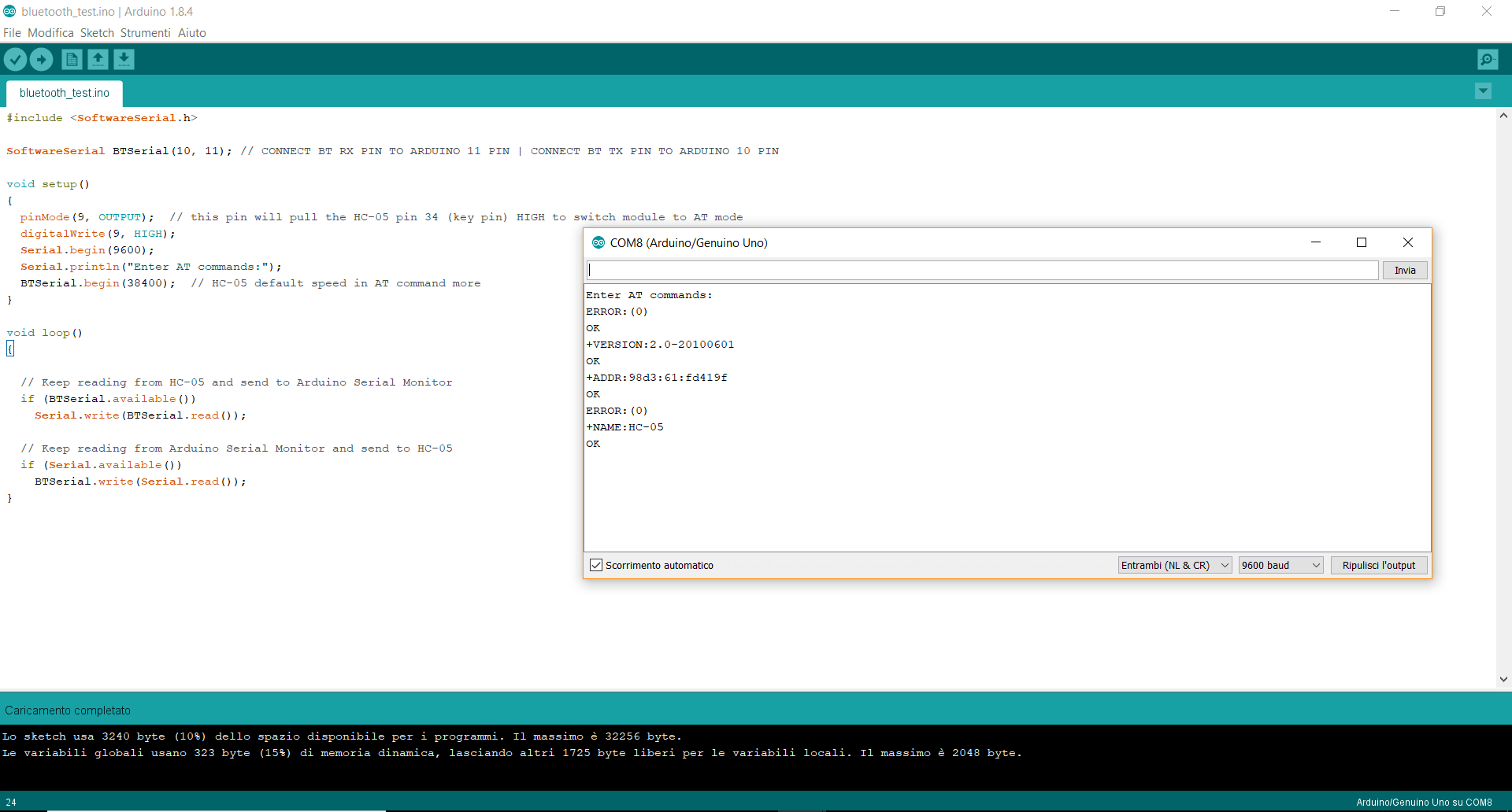
Here's the code I used to getting started with the bluetooth module connection. Now, I'm going to set up the second module. In other words, I have to set both devices roles via the AT+ROLE and only after this kind of action I will write the codes for my master and slave boards!
My practice with Bluetooth modules hasn't finished yet. I have to improve my knowledge on wireless communication and I'm getting used to do it during the final project development. If you want to check more about it, you can find all here
Useful links:
Serial CommunicationI2C - Wikipedia
I2C - Sparkfun
TWI introduction
GitHub - TinyWireS Library
Arduino Wire Libraries
Master Reader / Slave Sender
Master&Slave on ATtiny45
How Bluetooth works
Bluetooth datasheet
Bluetooth Interfacing with HM-10
Bluetooth guidelines
Bluetooth mate tutorial
AT commands
Bluetooth modules as master and slave
HM-10 module (Italian webpage)
How to pair bluetooth modules
AT mode guide (Italian webpage)
