Mechanical design
Things to do:
2) Build the passive parts and operate it manually
3) Document the group project and your individual contribution
Have I achieved this week's goals?
Brain storming
As each group project...the main thing is sharing ideas! After a restful night, we started talking together on the early Thursday morning. Seat around the table we started sharing different topics, even if we already had something in our minds. Antonio's suggestion was: "How about building a catapult?" and...as everyone can imagine, the following answer was: "To do WHAAAAT?!". So, we tried to find an aim for our machine project. Well, we will use it to throw us small paper notes that will include a professional message: "COFFEE?!"
Machine description
Basically, we decided to build a machine with 3 axis. In this way, everyone had one of them. Our catapult will have a rotating platform (X axis) and we would like to add the other two axis on its surface. So, my colleagues had the Y and Z axis. The first one provided for two parallel vertical arms and an horizontal one. It can be regulated in height and its main aim is to stop the catapult's lever. In fact, the last axis (Y) is the fulcrum of our machine. To check out a more detailed explanation related to the Y and Z axis, please go to Antonio Garosi's site (mechanical design - Z axis) and Giuseppe Allocca's site (mechanical design - Y axis).
Individual contribution
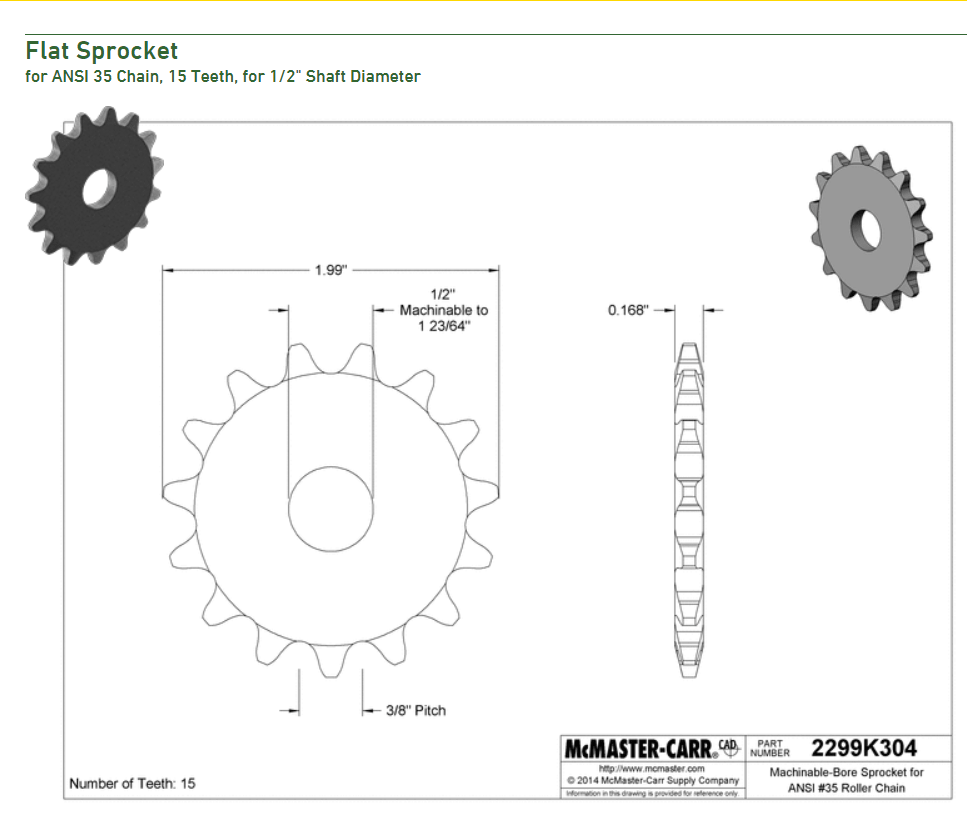
My contribution is related to the X machine's axis. I'm going to assemble a gear and its profile on the 3D software. They will allow us to move the round basis thanks to a stepper motor. In this way, the basis will be moved by the motor and the machine can rotate and hit the next coffee mate. Joking aside, I was really curious to browse on the McMaster-Carr Components website. Basically, I did it in order to look at the mechanical components details. I'm not really into mechanical processes and it has been a hard week, anyway I found it really useful to know something new. Thanks to some days of study, and the useful website I mentioned above, give you a complete overview of design components and this allows you to look at their characteristics. That's what I want to say:
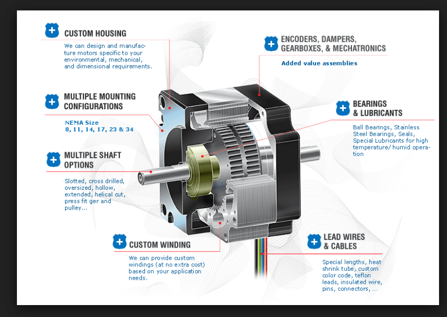
I've never done mechanic until now, but I already noticed the complexity of tecniques and the needed precision. My project part consists of a stepper motor rotating a round platform (similar to a record player). The stepper motor points shaft up and a small platform is attached to the shaft such that when the Arduino signals the motor to rotate 'number' of steps in either direction. Before starting, I deep studied how the stepper motor worked and I watched this video on YouTube and the other one here. Doing this, I knew we had the NEMA 17 inside the FabLab and it has been extremely useful in order to sketch the right dimension on the 3D software (Fusion 360).
Modeling - Fusion 360 and Adobe Illustrator
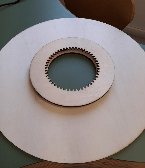
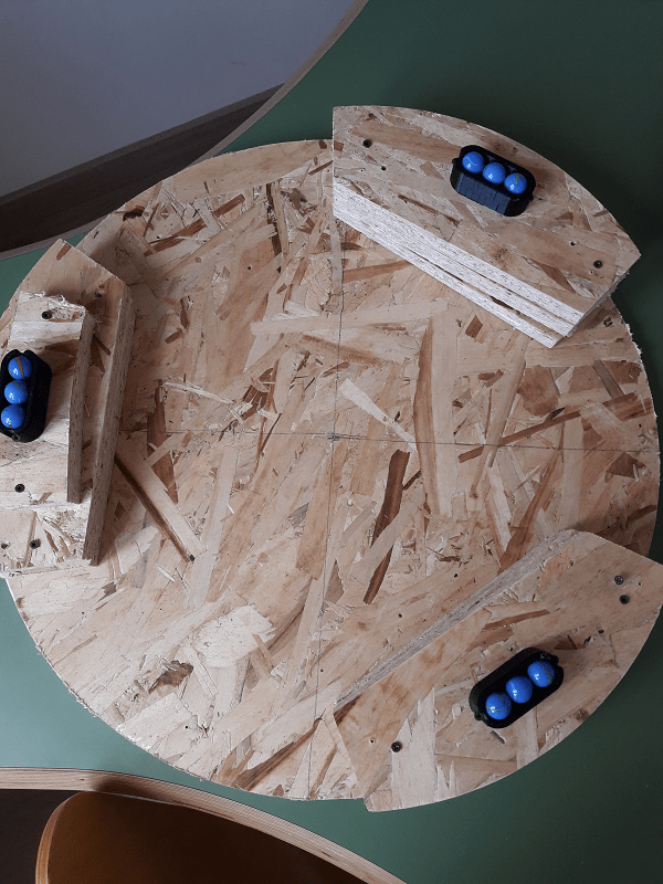
To semplify what I inspired by, you can watch how the Lazy Susan rotating table system worked. It's the best thing for a desserts greedy like me! Considering this fact, I would like to recreate a thing like that (more or less). Getting to the point, I first thought about the bottom support. In order to have a rotating plate up to it, it was necessary to design some small blocks to enlarge our machine height. I did it after having known the NEMA 17 stepper motor dimensions. So, two OSB blocks were enough (taking into consideration the material thickness = 18mm). After that I simply drew a circle on the 3D software, but this time I added a hole inside it (150mm). To sum up (until now...), we had the bottom support (OSB material), 2 overlapped blocks (x3) and the rotating basis (same diameter of the bottom one = 500mm).
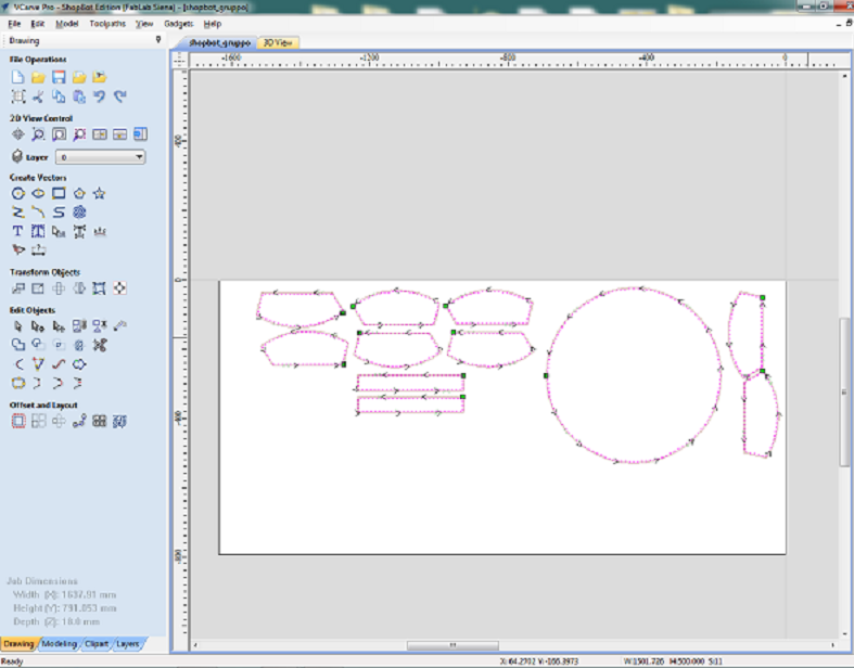
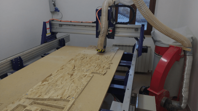
Then, I opened the file on V-Carve and I cut my components. Obviously, considering the safety measures, I used the ShopBot machine with Antonio, who had to cut two columns for his individual contribution. That's why you see 2 extra components on the screenshots. We add his components to my file in order to cut only once and save time.
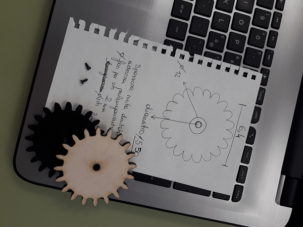
Next parts were the main ones and the most difficult. They were related to a gear and its rack. The first one, will be put on NEMA17 stepper motor thanks to a small extension that will be wedge in the stepper motor's pinion. The rack will represent the essential part to turn the plate. These two elements would have been fit perfectly together. I started watching some tutorials on the Autodesk website and on YouTube too and I started drawing them on the CAD software.
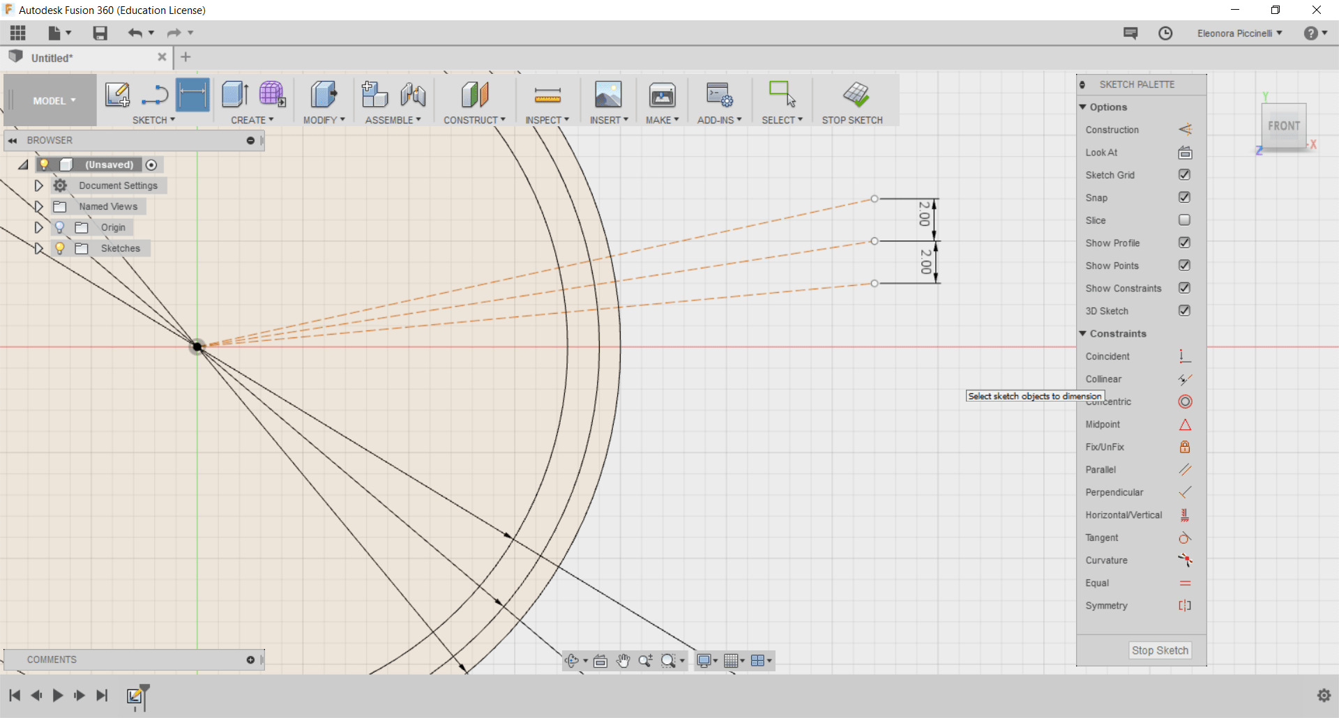
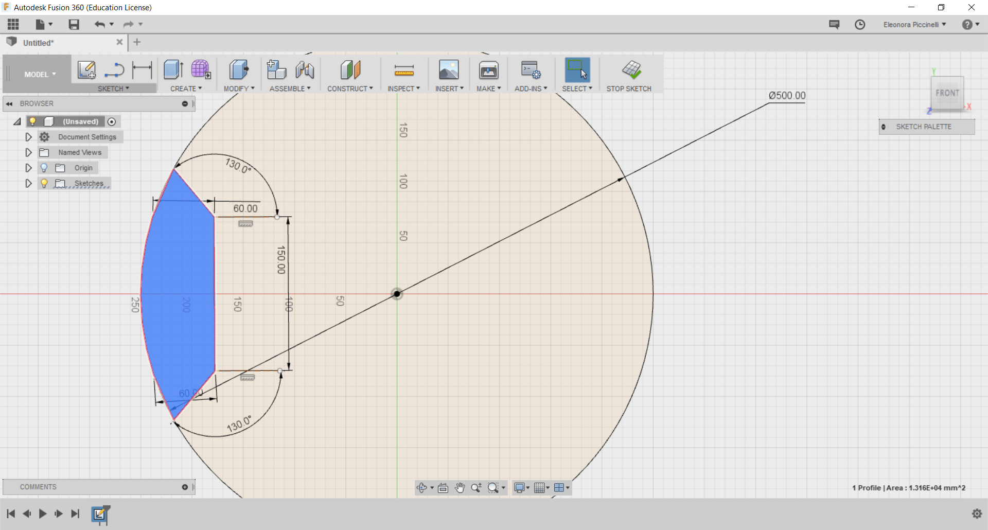
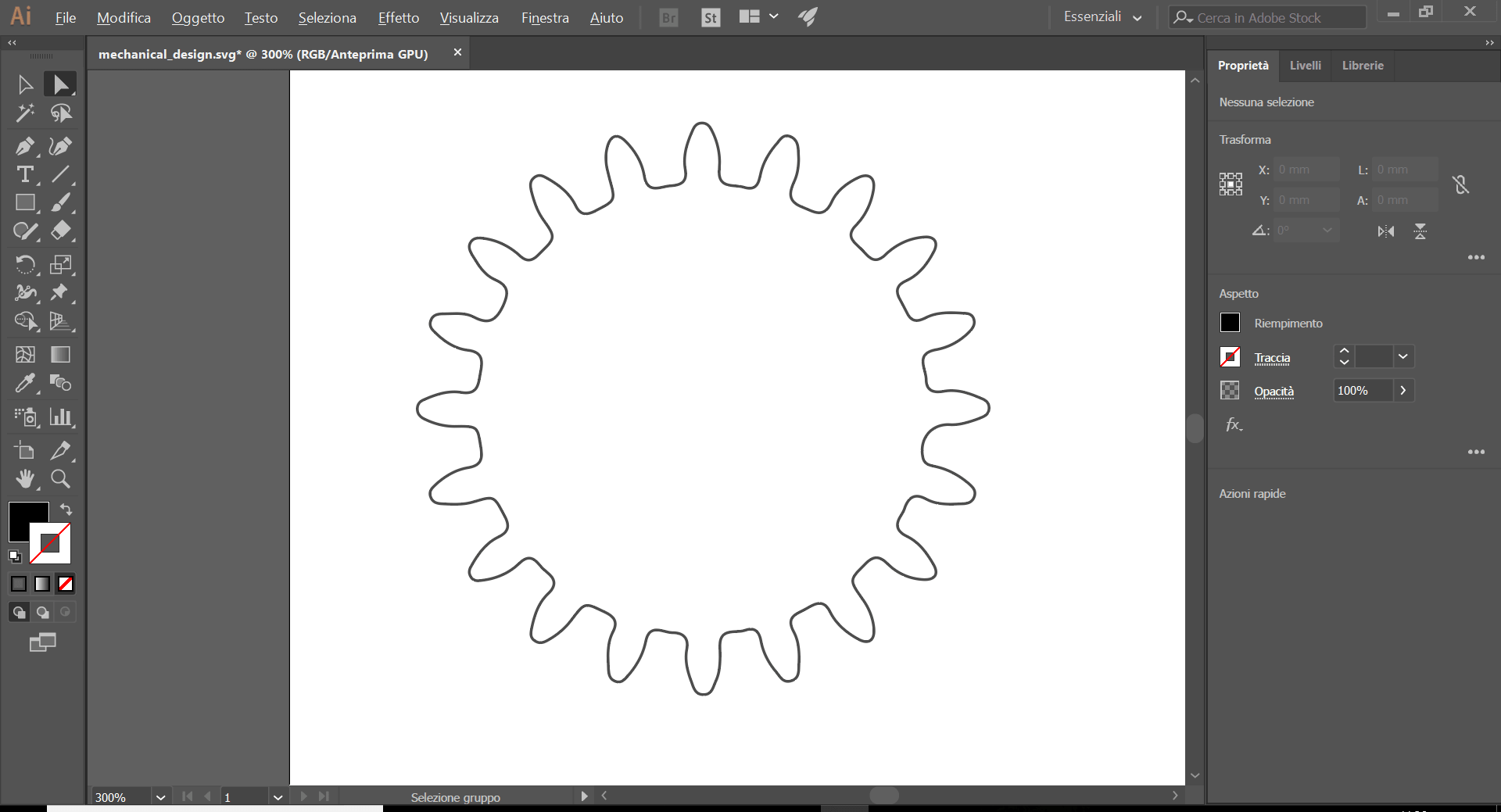
While I was looking for them, I bumped into this magic website that gave me the inspiration and the possibility to work in a shorter time. So, I saved the file on my laptop. Obviously, I wanted the gear and its rack as two separated elements, but they were considered as a single one on the 3D CAD. So, I opened Adobe Illustrator and after some tries I obtained the result I wanted. I coloured them into different colours and I obtained two different elements. Despite everything, I couldn't edit them on Fusion because their dimensions were considered as "drive dimension" and I couldn't change them to be adaptable on my rotating platform and the stepper motor. After having checked some information on the Internet, I did some tries and then, I simply changed the way in which I select the elements. Thanks to a direct selection option, I could change the features of my objects. As you can see, the external diameter has changed and I worked in order to edit the components following my needs.
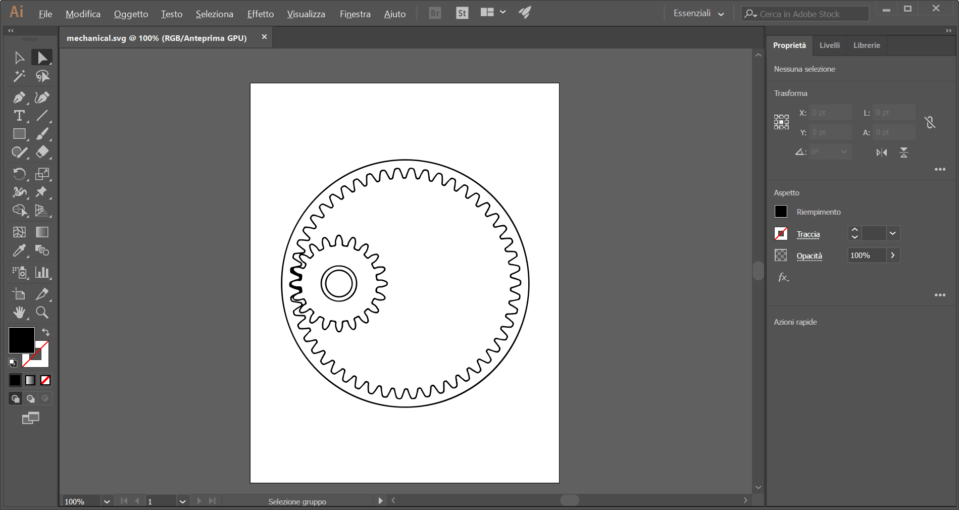
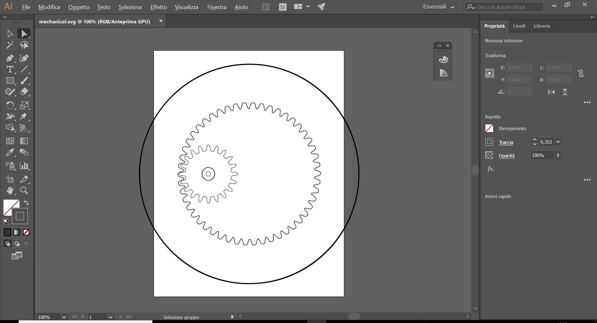
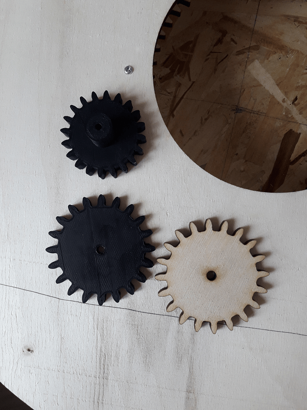
After having finished, I saved my file on a .dxf extension and I prepared it to be cutted with the laser cutter machine. Let's see how it came!
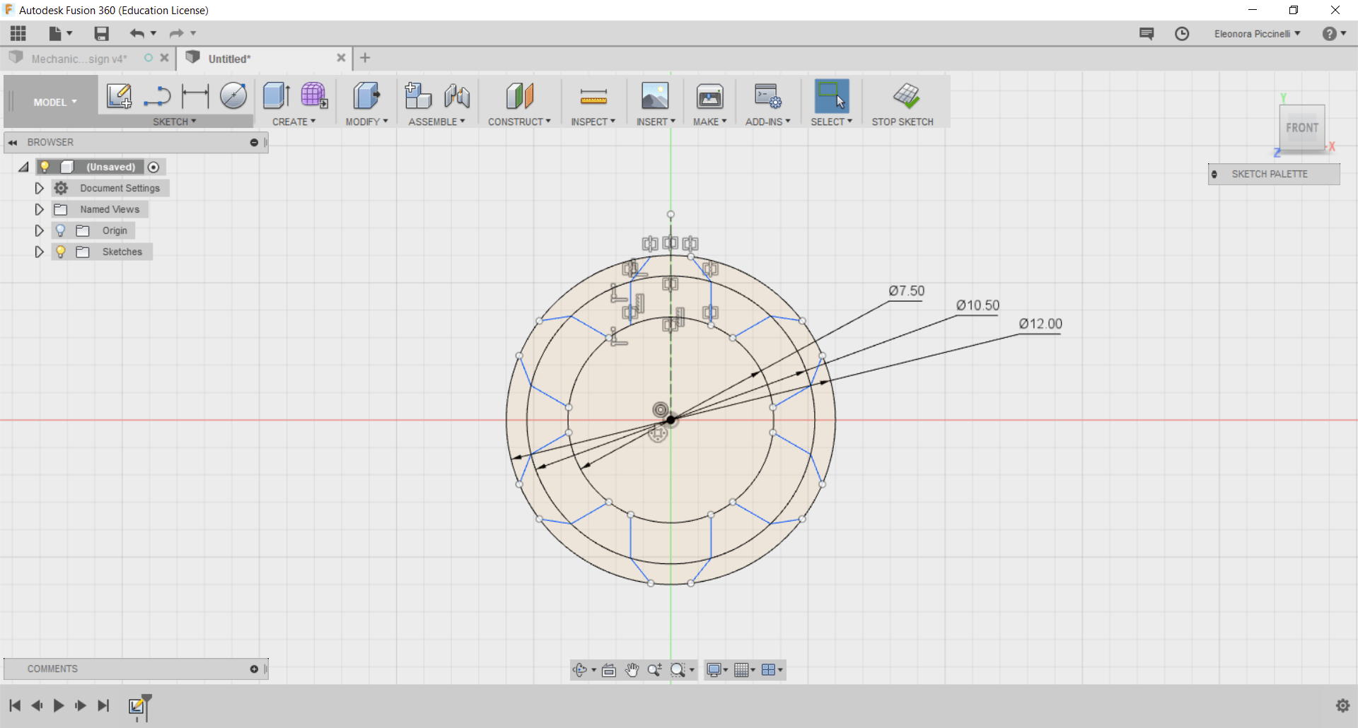
Moreover, considering the fact it worked properly, I thought it was easy to add only the pinion's extension and print the object with the Ultimaker. I completely got wrong! It was smaller then the first one, and so it would have been lost pitches during the movement. I came back on Adobe Illustrator, after having opened the same file, I deleted the rack (that was ready) and I focused my attention on the gear. First of all, I did a quick test. How about editing the dimensions and trying to open it on the CAD? That was exactly what I did. I immediately noticed that the dimensions I set on Illustrator wasn't the same I wrote. In other words, the file came back to its original dimensions (the same they had on the website). So, I thought it would have been an unending problem and I decided to add some mm to the external diameter on Illustrator and I joined the traces. Then, I saved the image and I opened it on the CAD.
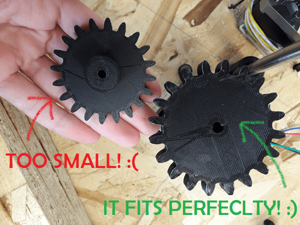
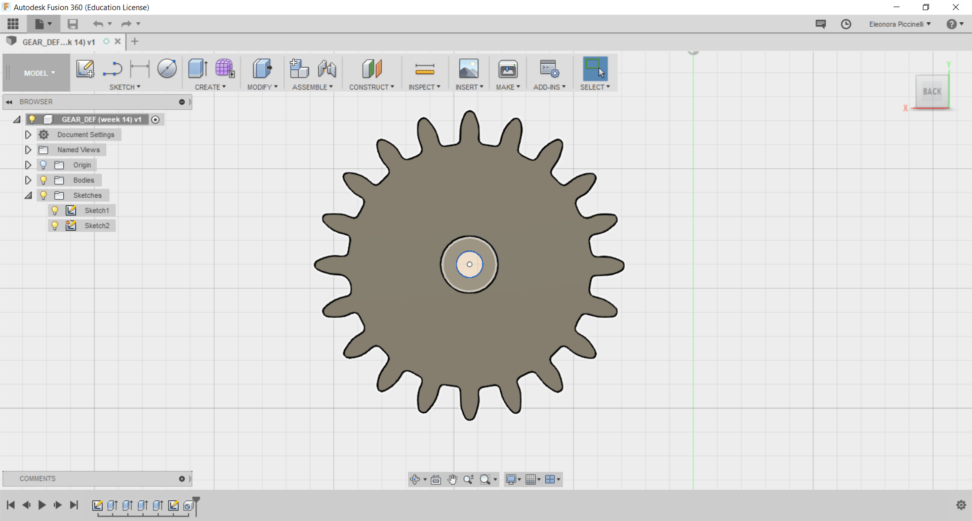
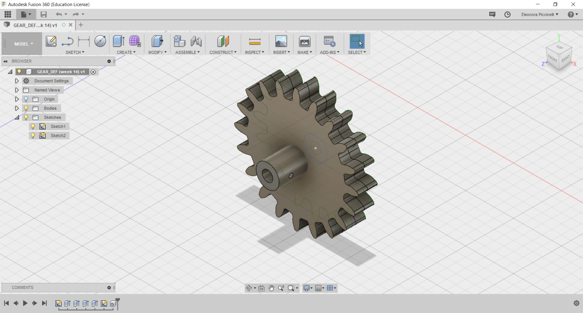
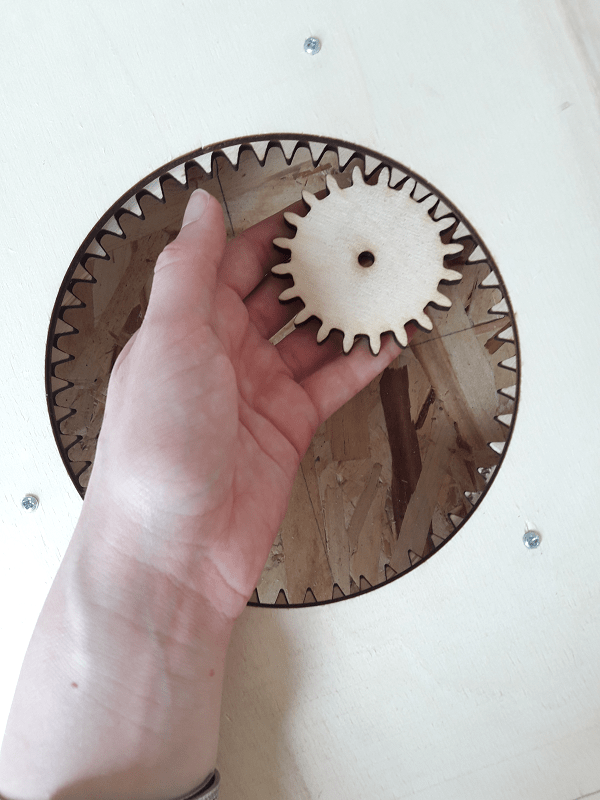
Fortunately, the way of thinking has worked well and the dimensions were correct. I simply add a drill (centered point) on my gear and I gave it 5.50 mm (in this way, it would have been fit perfectly on the stepper motor's pinion). Finally, I drew the extension related to be slot in the pinion and I added two lateral small drills (2mm). Doing so, I would have insert two small screws (3mm) inside them. Considering the fact, their diameter was bigger, it would have helped me to fix the gear to the pinion and be sure of its stability at the same time. I set the values I wanted on Cura and I started my 3D printing! After a couple of hours, that's the result! It has the perfect dimension.
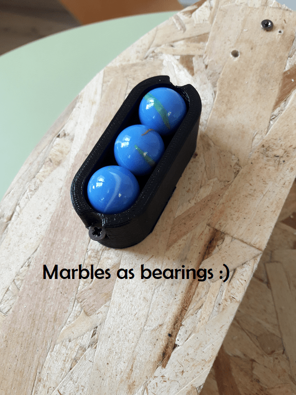
In addition, I decided to use other elements in order to avoid rolling friction on the wooden supports and the rotating basis. For this reason, some marbles (round glass toys) would have helped the rotating table a lot. Antonio kindly suggest to create some small boxes to put our marbles inside. He did a quick design on his 3D software and we immediately went to print the pieces with the Ultimaker. After that, I proceed assembling all my components. I had all I needed!
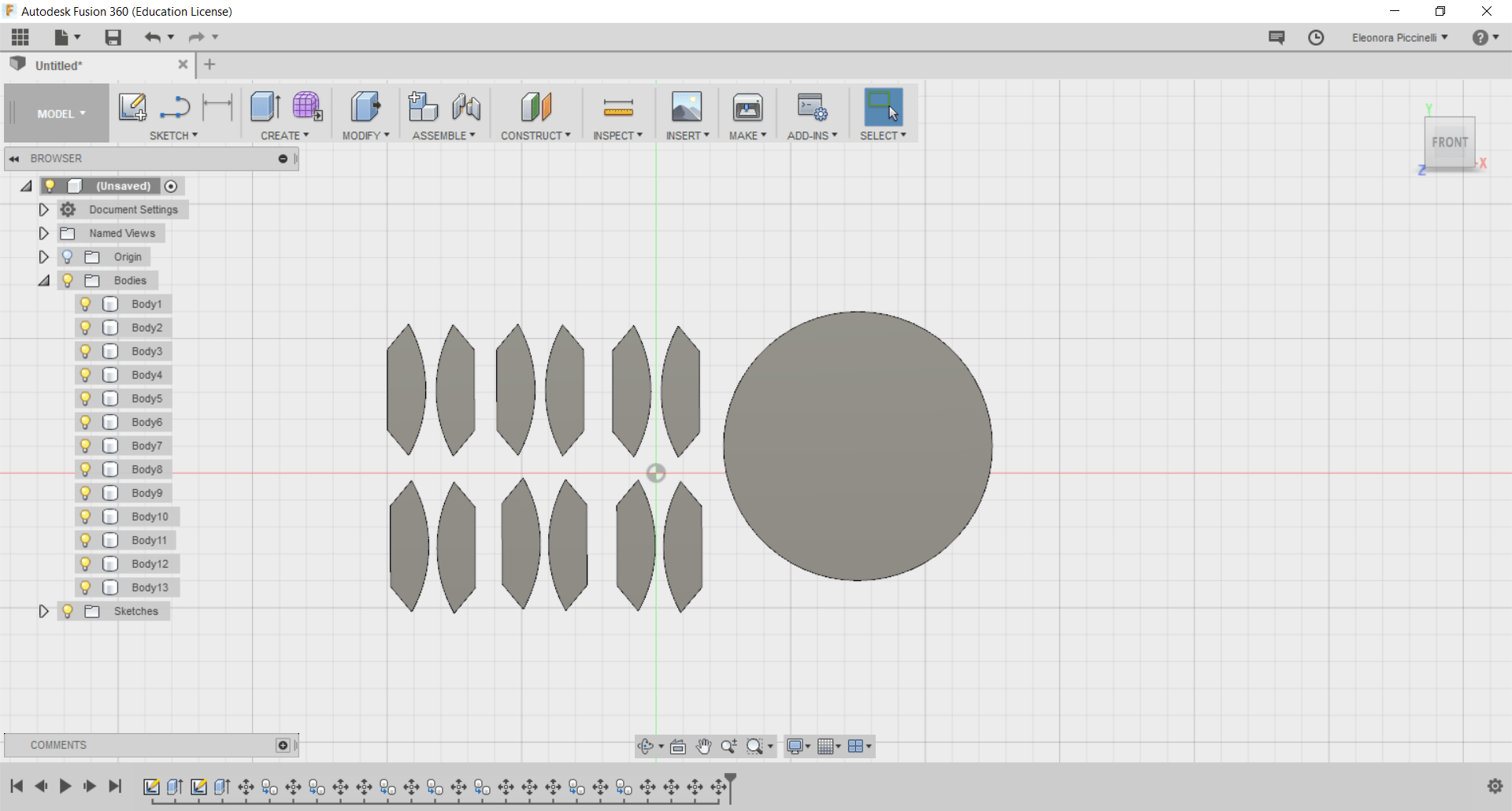
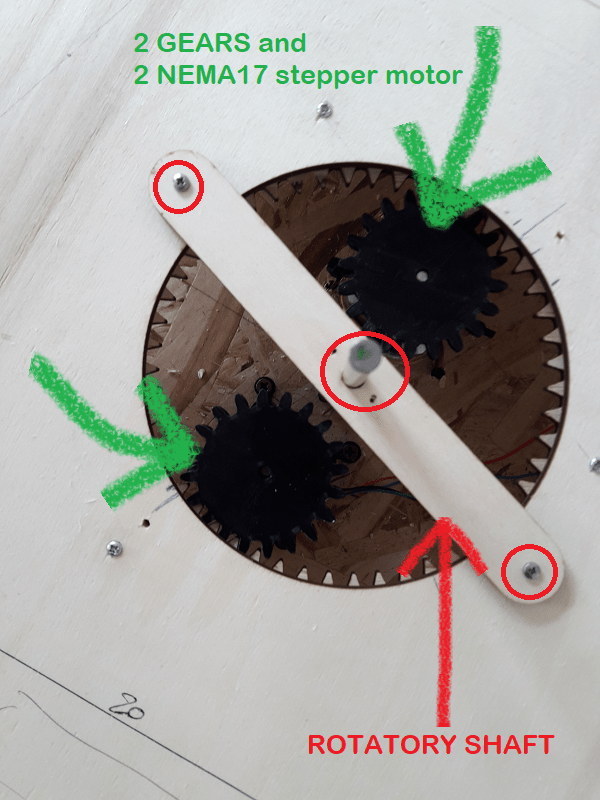
Considering the fact, only one stepper motor wasn't enough. The 3D printing related to the gears has been repeated 2 times. As you can see, we all noticed that a second stepper motor was required. So, here's the final solution.
Now, I'm going to show you how it works manually! ;)
Future development opportunities
More that this, I tght about future improvements. As evrey respectful project, I'm pretty used to think about re-design steps. Maybe, the rack and the pinion would have been better set on the external part of the rotating plate. I mean, probably only one NEMA17 stepper motor would have been enough because of the absence of overloads.
Conclusion
It has been the most challenging week because of the great quantity of concepts we had in mind. Anyway, we always found a solution in order to avoid unending problems. After having tested our individual part manually, we are going to try all the three axis together and start using G-CODE, CNC shield and the Arduino.
Useful links:
NEMA 17 - DatasheetMcMaster-Carr
Gear Generator
Mechanical assemblies - Fusion360 tutorials
Integrated CAM on Fusion360
How does a stepper motor works? (YouTube tutorial)
How to use a stepper motor
Parametric pulleys on Thingiverse
Make a gear on Fusion360
Planetary gear on Fusion360
Turntable idea (YouTube tutorial)
Download:
Here, you can find the files related to my individual contribution. ---> MACHINE BUILDING.zip
To check out our whole machine project, please go to the group webpage
