Computer-controlled cutting
Things to do:
2) Design, make, and document a parametric press-fit construction kit, accounting for the lasercutter kerf, which can be assembled in multiple ways
3) Cut something on the vinylcutter
Have I achieved this week's goals?
Vynil cuttingLaser cutting
Vinyl Cutting
This week I used the Vinyl Cutter for the first time. I enjoyed it a lot! Sometimes it's understimate, but for me it's really cool.
First of all, I carefully listened to Flavio Lampus guidelines. After that, I used Google Images looking for a black silhouette with some written inside.
I liked
this one and I saved it on my computer to use it for my first weekly assignment.
I opened my picture with InkScape (Ctrl + O)

Then, I clicked on the option you can see around the red rectangle outline.
That command is essential and allows you to print the picture mantaining the same quality.

The following action was related to an update (without editing the default parameteters!!)

After that, I clicked on the lock at the top of the page to fix the dimensions (height and length)

So, I resized the picture, changing the dimensions (look at the screen below)

Finally, I saved my image as a new file, but I used a .png extension

After this theorical part, I saved the picture on my USB pen and I put it on the computer that was connected to our Roland GS-24.
So, I opened the file on the FabLab computer, I selected my picture and I clicked on "image profile" after the right click on my mouse.

The new menu gave me the option related to an other essential command: extract contour lines. So, I clicked on it!

At this point, I obtained two identical pictures (they were overlapped). I moved the first one and I deleted the other one.

Finally I cut the parameters clicking on File - Cutting Setup and I confirmed my choices clicking on the button "GET FROM MACHINE".
Thanks to this last action, I sent my parameters to the software.

At the same time I put the vinyl sheet inside the Roland Plotter. I pressed the button Enter to place the knife to the origin. Finally, I clicked on File - Cutting. Last but not least, I removed the extra material and I covered my picture with a transparent sticky film. I paid attention to the adherence between my shape and the film I used. After few minutes, I would have removed the sticky film to obtain my final result, but I decided to bring it back with me to paste it in front of my bedroom's desk as a daily reminder!


Laser Cutting
This was a more difficult assignment but I had never give up! Even if I didn't do a complex object, I really understood the main things related to 3D models and laser cutter machine. In order to explore parametric's model world, I decided to use SolidWorks because I noticed it was similar to OnShape (I used it during the last week!). In addition, our instructor suggested us to try different softwares to understand which one is more appopriate for our skills and savours. Solidworks is a great parametric software, even if I'm not very practical at all. I tried many times before extrude my last version. I found some difficulties in drawing directly on the online sketch. For this reason, I decided to draw my model on paper. It has been easier to understand all the joints.
At the same time, I opened the software and I clicked on new file. First of all, I wrote down the variables tools --> equations and I gave the parameteres I wanted. Then, thanks to some basic guidelines, I created my first object's attempt. I know it isn't an extravagant object, and maybe, also a trivial thing for expert people, but 3D parametric modeling has been demanding and I'm still working on it to improve. When I finished my first test I decided to bring my wooden board and do some exercise. In the first case, I understood I put a wrong speed or power. Then, I thought I didn't put the lens focalization properly. Why am I saying that? Because I tried to cut my wood board with the following parameters: Power: 85 / Speed: 0,4 but my board wasn't nearly cut! I made a second test, trying to reduce the Power: 75 but using the same Speed: 0,4. This time my model's parts have been cut! So, the last two parameters have been the right ones and I'm going to use them!
First of all, I tried to watch some guidelines on Solidworks' website and I looked for the information I needed on the left side drilldown menu. Then, I opened the software and followed a specific tutorial I found on the Internet. Before modeling, I went on tools --> equations and I added the values in the box below. This was the essential step to build a parametric 3D model. I gave a quote to the height, the lenght, and the depth. In addition, I specified the material thickness (6mm in my case) and I added the kerf value after the test I made with my group.
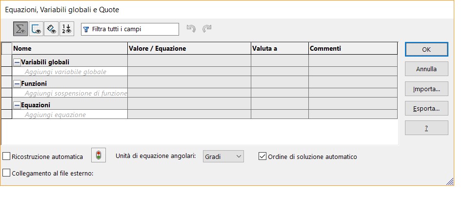
Then, I started drawing my picture including the global variables I determined inside the equations box. As you can see, the height and the lenght both have a defined dimension and the ∑ symbol shows how the X variable depends on the Y variable (or viceversa).
This means you're going to build a parametric model!

As you can see, I did a mistake when I created the last two sections. Their quoted values were completely wrong.

In fact, I decided to correct them. In the screenshot below, all the sections have the same dimension and they are perfect aligned with the others.

Anyway, I observed I did lot of mistakes because I forgot some essential passages. For example, I missed to set the slope.

After few updates and some corrections, I set the slope in the correct way and I consequently obtained the ∑ symbol on each sections I drew.

Finally, I'm going to show the photo about my first test on the wooden board. The shape on the right was the first one, and the second on the left was the last. This picture provides the evidence of wrong parameters in terms of speed and power (shape on the right). The second shape was quite better and gave me the opportunity to assemble my printed parts.

However, I discovered I used a quite right dimension for male and female (because the joints were only a bit large) but I did a mistake with the others dimensions (even if the joints were quite good, one side was too short in lenght!) Getting to the point, I will try to work on this assignment and I'll surely upload this section with screenshots and other improvements.
Considering the fact, I'm still trying different software, I decided to do a parametric model on Fusion 360 too. I didn't appreciated it last week, and I would like to know if I'm able to draw a parametric model on it too. The experience with Solidworks wasn't bad at all. Even if I hadn't obtain a final model, I did some practice with its tools. At the beginning, I thought it was easier to be used, but it has a great potential and it is well organized. For the moment, it's too chaotic for me. So, as I've already said, I started modeling on Fusion360. As I did on Solidworks, I immediately set the dimensions to write my functions.

Then I drew my model and I also realized that a jewel box could be parametric but it wouldn't have had any kind of modularity. How could I assemble it in different ways? So, I hadn't new and innovative ideas, but I started drawing paying attention to male and female joints and taking into consideration the material thickness. I drew simple shapes: particularly, I thought about a new kind of library that likes me so much. Basically, it is made up of regular blocks of material and it is placed on the wall in following a zig-zag shape. So, the idea is related to the latter example I mentioned, but I also wanted to try different kind of objects assembling the pieces in various ways.
Fixing problems
After having drew on 3D software, I cut my model with the laser cutter. Before doing it, I saved the file on a .dxf extension (I didn't know how could I do on Fusion and only at the end I understood I had to click on Sketch ---> Right button press ---> save as .DXF. Honestly, I spent much time in looking for this option, but fortunately I found it! Then, I opened my file on Adobe Illustrator, I moved my elements and I repeated the shapes for the number I had in mind. I used the setting I mentioned above (with Solidworks test), but this time...the wooden panel was warped. It would have been better fix it with some wax blocks or something like that on the edges. But, honestly I didn't think about that! So, the final cut came out, but the pieces' edges weren't regular becuse of my oversight and male and female were good only to be joined few times. If I would have levelled the material, the kerf would have been cut in a precise way. On the contrary, some parts of material burnt a bit more than they should. Consequently, the model can be considered such a press fit kit but I suggest you to assemble it few times instead of trying to moving parts. The first three shapes can be seen as a test and confirm the modularity feature. The last one is the shape in scale of a possible library to be fixed (horizontal) on the wall!


Useful links:
Fusion360 OFFICIAL YouTube ChannelMaking parametric models
Parametric modeling on Fusion360 (YouTube tutorial) 1/2
Parametric modeling on Fusion360 (YouTube tutorial) 2/2
Sized finger joints
