
Here we are at the practical part of my project: the
Hardware
.
After
talking
about
the
conceptual
part
and
Software,
it
is
time
to
implement
the
knowledge
and
technologies
learned
during
these
months
of
participation
in
the
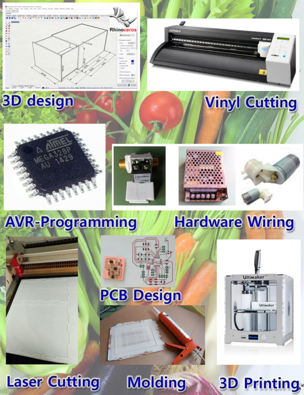
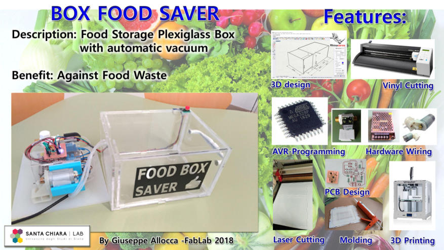
course.The
used
technologies
are
shown
in
FIG.A
,
it
will
be
interesting
to
see
how
the
synergy
between
the
various
parts
is realized and to understand the functioning of my “Box food saver”.
FIG. A : Used Technologies
First
of
all
it
was
necessary
to
prepare
a
scheme
that
would
help
me
to
define
the
roles
of
the
individual
components
and
how
they
relate
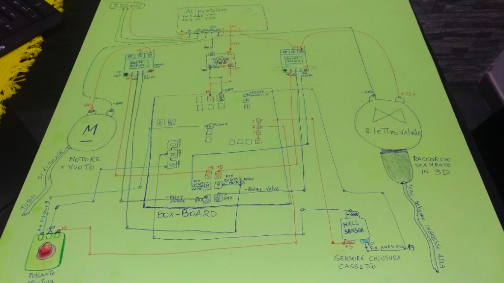
electronically.To
make
my
sketch
(
FIG.B
),
I
bought
a
bristol
sheet,
colored
pens and a little brain!
FIG. B : Draft of Project
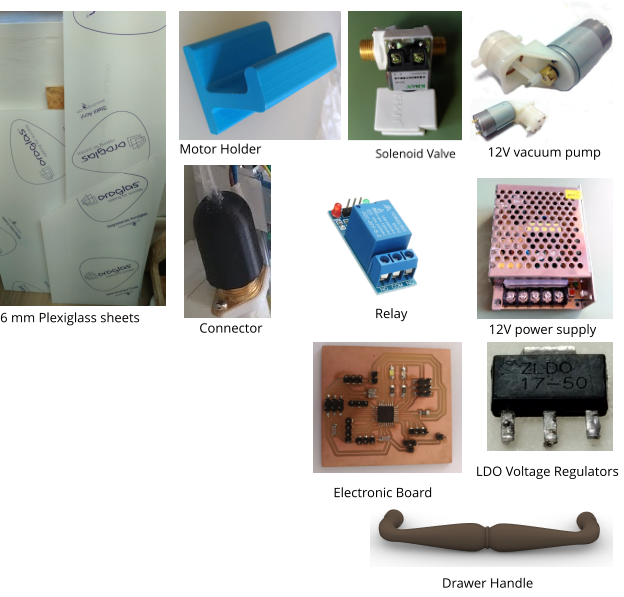
The components used in the project
List of Components:
6 mm Plexiglass sheets
1 Power Supply (220V AC to 12V DC)
1 Vacuum Motor
1 Motor Holder
1 Solenoid Valve
6mm Silicone Tube
1 Button
1 Magnetic Sensor
2 Relays
1 LDO Voltage Regulators (12V to 5V)
1 Electronic Board
1 Drawer handle
Connection Cables
1 Connector between solenoid valve
and silicone tube
1 Button
The idea of the Box food saver, the role of the components
The basic concept is to create a vacuum inside the box by extracting the air.
When
we
want
to
open
the
drawer
to
pick
up
our
food,
we
can
simply
press
a
button.We
see
the
role
of
each
component
in
this
apparently
simple
process,
but
that
requires many interactions.
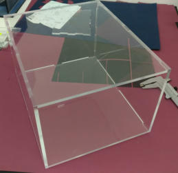
The Box
To make the Box, I chose Plexiglass as a material because it has many positive characteristics.Plexiglass is suitable for food and its transparency allows you to see the contents.This material is very compact and cuts well with the laser, the joints made are very precise and have a good anchorage.
In the Week I learned to use the laser cutting machine, I performed tests on the Plexiglass and realized a tetris-inspired interlocking game.
It was a very interesting experience to learn the parametric design and how to cut with the laser.
This is the link if you want to see what I have done:
“Computer-Controlled Cutting : Laser Cutting”
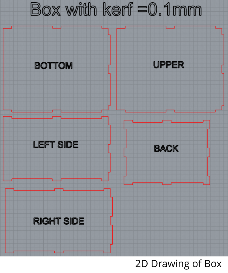
Thanks to this exercise, I was able to measure the kerf and find the correct parameters for the processing of my final project:
Kerf: 0.1 mm
The Laser cutter machine: Speedy 400 by trotec
P=100.00
V=0.13
Laser Power=2000
The
best
result
was
:
the
square
of
10.2x10.2
(male
that
reduces
and
becomes
10x10
mm)
the
square
9.8x9.8
(female
that
widens
and
becomes
10x10
mm) we have two cuts …. then 10.2mm - 10 mm = 0.2 / 2 (two cuts)= 0.1 mm kerf .
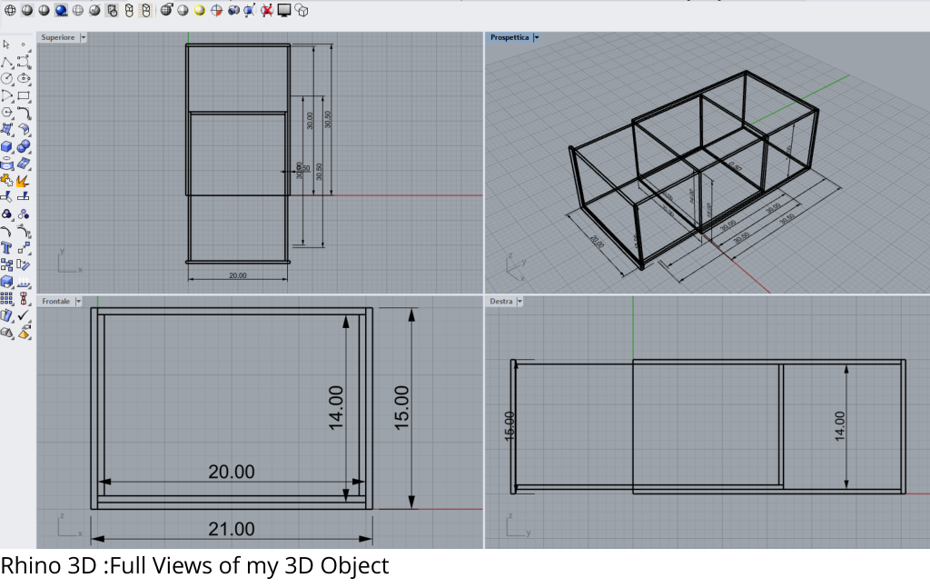
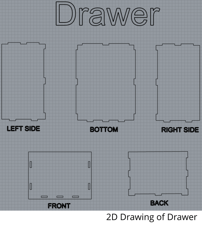
2D / 3D CAD design
Having the parameters to perform the cutting of the plexiglass, I can begin to draw the pieces to build my Box.Thanks to what I learned in the " Computer-Aided Design " week, I realized the project of the external Box and of the internal Drawer, using the Rhino 2D/3D Modeling Software.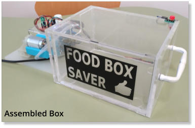
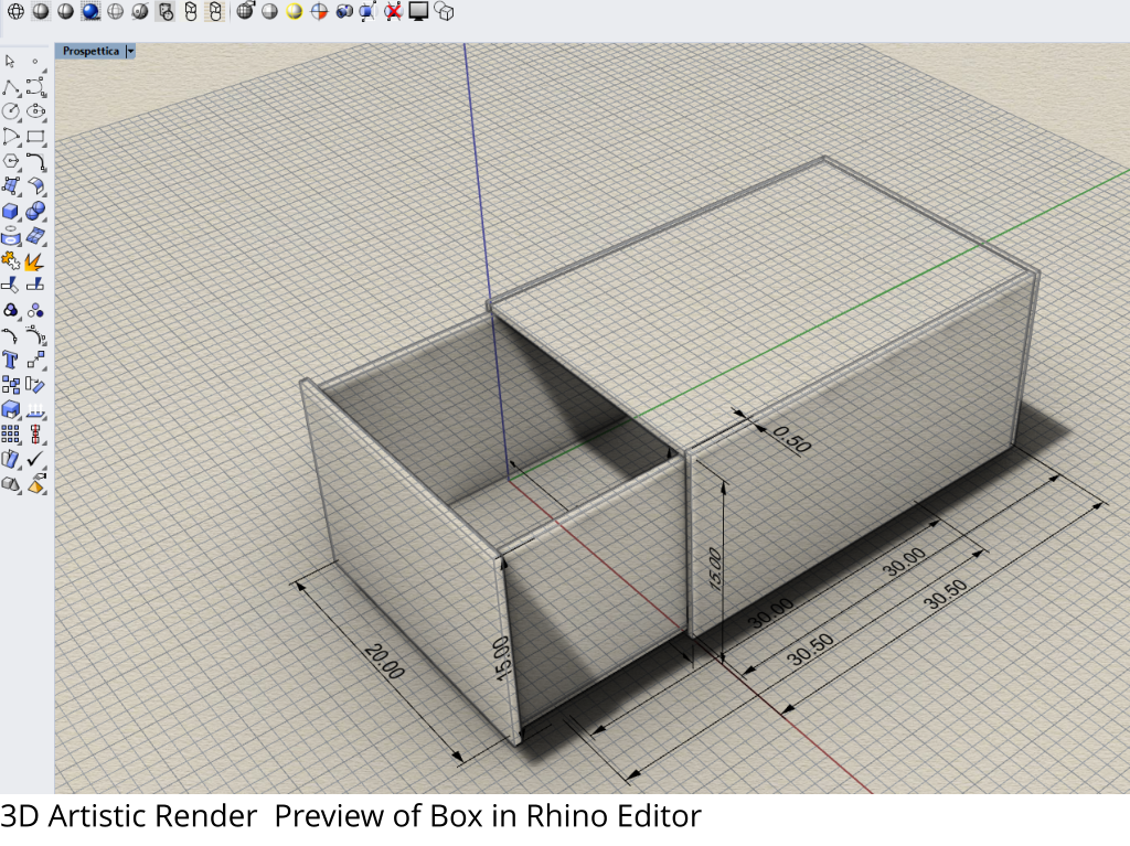
Start cutting!
From the Rhino 3D File menu, I can select "Export" and save the cutting files in .dxf format to load them into the laser machine software and proceed to the cut after setting the correct parameters, this includes the positioning of the plexiglass on the plane, the focus setup of the lens by adjusting the height with the appropriate tool.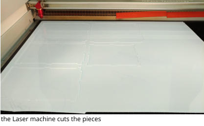
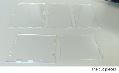
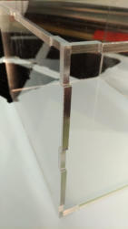
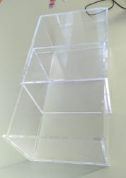
Assembling the pieces
Here we are assembling! This phase was particularly exciting, because the project materialized ... we passed from the abstract to the reality and this was very gratifying. One advice I can give to all those who decide to work with the plexiglass is that this material must be handled carefully because the corners are particularly delicate .You must be very careful, especially when assembling the pieces , to prevent the cut part from splintering.
Joining the pieces
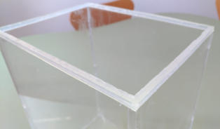
Assembled box
Corner junction
Box and Drawer
Sealing Gasket
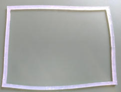
To ensure a good closure of the drawer, I thought to create a silicone gasket, using a mold made by cutting a rectangle from a plexiglass waste. I put some tape to hold the part to work, then I removed only the rectangle leaving the vacuum to fill with the liquid silicone. The practice with these materials and the basic concepts acquired during the " molding and casting " week was useful to me.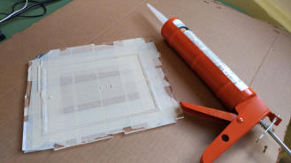
the mold filled with silicone
the gasket
the gasket glued on the edge
connector for solenoid valve and silicone tube
Self-built Components
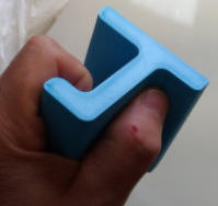
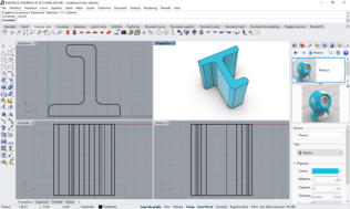
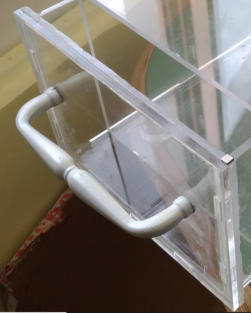
Thanks to the week dedicated to 3D printing , I have the necessary skills to make the three pieces I need for my project. The first piece is the handle for the extractable drawer, the second is the support for the vacuum pump, the third and last is the connector that allows me to connect the valve and the silicone tube.As I did to design the Box, I use the Rhino 3D Software to create the 3D models of the necessary pieces, not within the details of the realization as it would be off topic, and the procedure is the same as already fully illustrated.
Motor Holder
Drawing of Pump Holder
Connector
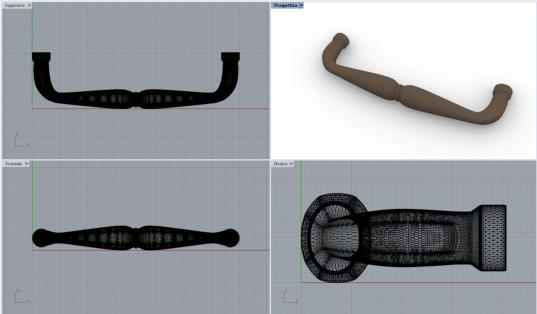
The handle was printed with a black filament, I did not like the color and then I used a white acrylic paint to change the handle color.
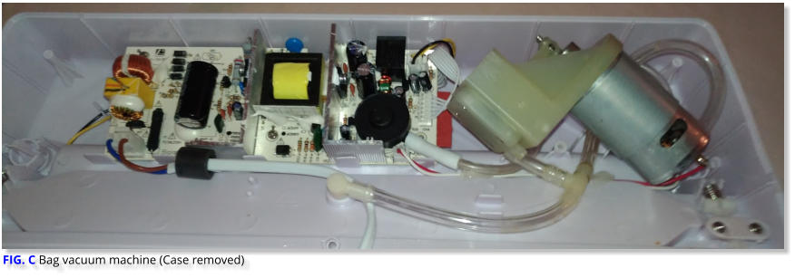
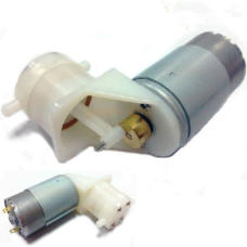
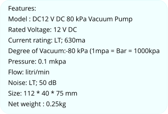
The Vacuum Pump
This component does not need many explanations, it serves to create a vacuum inside the Box. The use of the vacuum pump is very simple, you only need to supply a 12V current by connecting the negative and positive pole to the motor.To choose the type of pump to buy, I thought about disassembling a vacuum machine ( FIG. C) that works with the bags, which I had at my house.In this way I was able to identify the exact model and the brand to order it on the Internet :
The handle modeling in Rhino 3D (just make a half and then a mirror copy)
The handle painted in white
The Pump and The Valve :How to Use
In my project I use a relay, activated by the software of my electronic board, to control the start and duration of the Pump operation. Next we will see the connection scheme with the relay.I have tested the solenoid valve with the pump and the two relays to verify the correct functioning of the components. Below you can view the video of the Test in my Vimeo channel.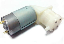

The Solenoid Valve
The role of the Valve is twofold.When the pump creates a vacuum, the valve must prevent air from entering the Box, so it will be closed. Vice versa, when the button is pressed to open the drawer, the valve will open by letting in the air which will cancel the vacuum seal, allowing the drawer to open.As we have seen for the pump, also the solenoid valve has simply two contacts, one per pole, equally controlled by a relay that is activated and timed by the software of the electronic board. The valve has two threaded sides and the electrical part is closed inside a plastic body. ( FIG. D)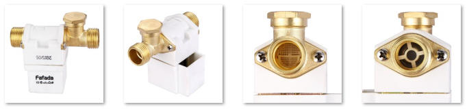
FIG. D
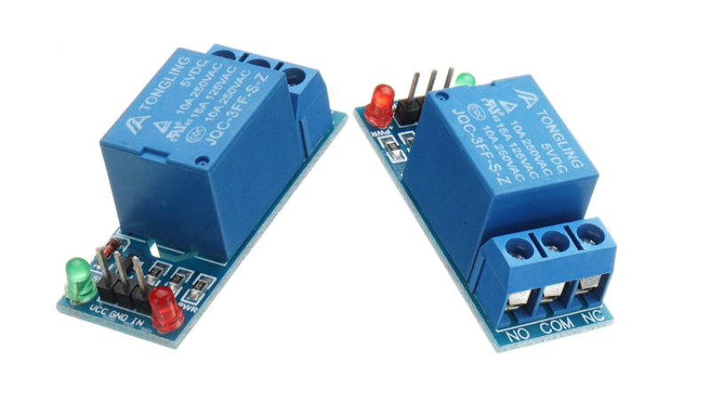
The Relay
A relay is an electrical switch that closes or opens a circuit thanks to an electrical impulse.In my project, I used two relays to control the start of the vacuum pump and the solenoid valve.The relay seen from above has connections on both sides.( FIG. E) On the left side we have three contacts, VCC = + 5v, GND = - Negative, In = inpulse on digital pin. These contacts are connected to my electronic board. On the right side we have three screw connectors, NO = Normally Open, COM = Common Port, NC = Normally Close.The central part (COM) is the power supply current of 12V Dc that comes from the 220vAc-12VDc transformer.In my project I used the NO (Normally Open) output because I need to activate the component, if I needed to interrupt a current flow, I would have used NC (Normally Close).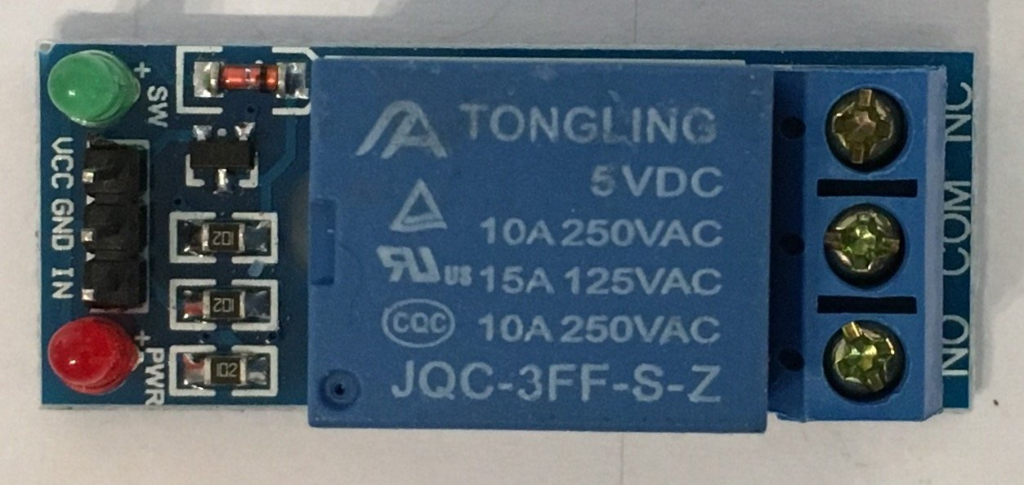
(
FIG. E)
The Magnetic Sensor
This component is fundamental because it allows the software to check if the drawer is open or closed.The sensor is placed at the top on the right, in the front part of the Box, where the opening for the drawer is located.On the upper edge of the front of the drawer, in the upper right corner, there is a small magnet. (FIG. F) The magnetic sensor detects the presence of the magnet and sends a different reading of the value, this variation is interpreted by the software and allows to manage the dynamics of the program.During the "Input Devices" study week, I learned how to manage this sensor, both for hardware and software.http://fab.academany.org/2018/labs/fablabsiena/students/giuseppe-allocca/input%20devices.html
In the first use I made a trivial mistake and for this I had to create a new card. I'm glad I was wrong, because the new version of the card was useful for the final project. My mistake was to connect the magnetic sensor to a digital pin, this is wrong because the sensor needs an analog pin. Please keep this in mind if you want to use this sensor in your project!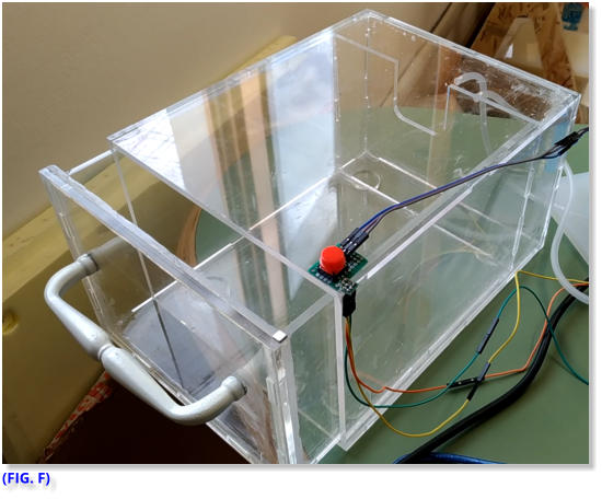
How to Use The Sensor:
The Pin-out Diagram ( FIG. G ) shows the three sensor pins, which are: vcc +5 (pin1), -GND (pin3), VOUT (pin2). This last pin (Value Out) is the one that will return the value read by the sensor, sensitive to the magnetic field of the magnet glued on the front of the drawer, and read its value using an analogue input in our circuit.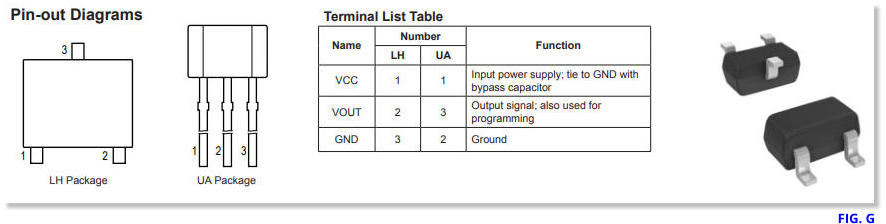

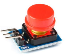
Push the Button!
Although it is an extremely simple component, the button has the function of sending the opening signal to the electronic board, which activates the valve to eliminate the vacuum and allow the drawer to open. The button has three pins: + 5V , - GND, OUT (to Digital Pin) I chose to place the button on the top of the Box, on the right side. Obviously, the position can be changed, but it must be a convenient position to use.The Main Board
The heart of everything is the electronic board that constantly controls the status of the button and the sensor, the programmed algorithm understands if you want to open the drawer or if we have closed it.For more details about the Software, please refer to the dedicated page. Here is the link: Box Food Saver Software Page As I have learned in past weeks , to create my electronic board, I have used the “Eagle” software to prepare the schematic ( FIG. H ) and the electrical connections named Board ( FIG. I ). For this board I decided to have more pins available for further development. I think it is useful to multiply the power and ground pins in more contacts and also have extra pins available. The Microcontroller chosen for the realization of the control board is ATMega328p TQFP (as indicated in the list of components FIG. L ). I decided to use this processor because it offers many pins to use and I like this because I can foresee possible additional sensor connections and more. For more details on the creation of the card, this is the link: Board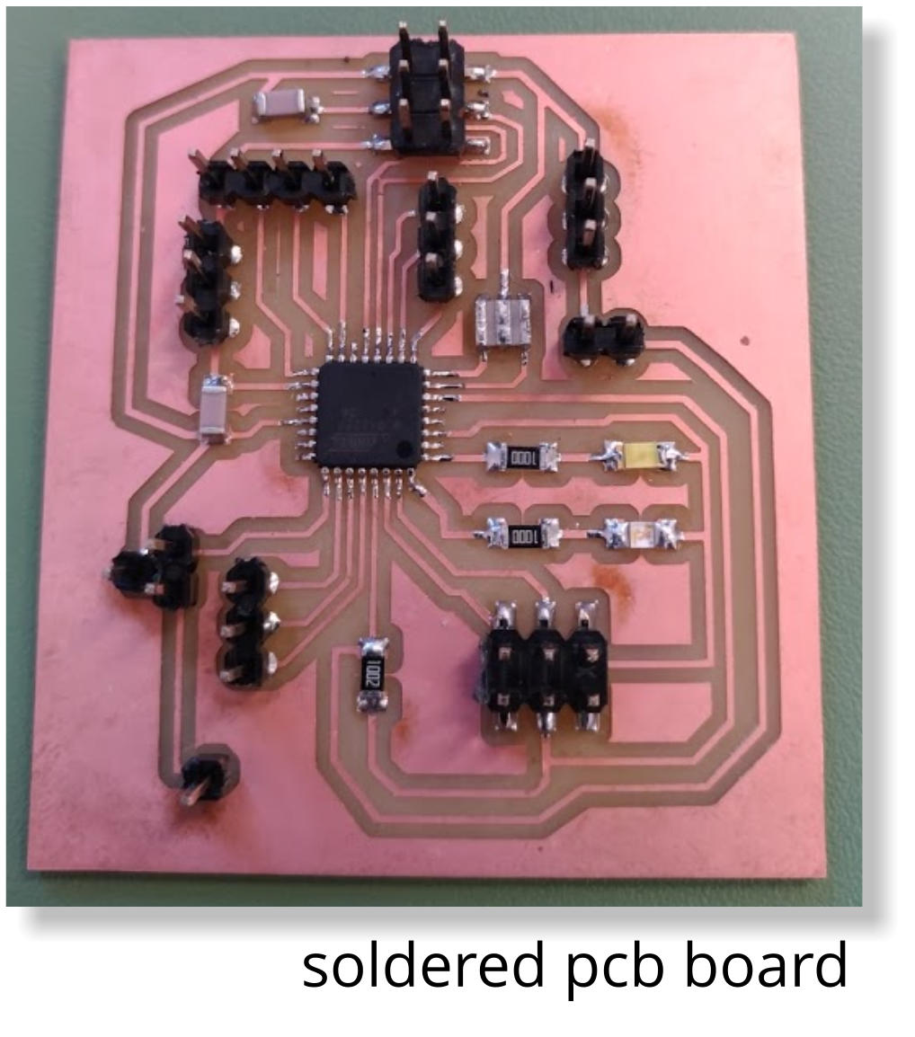
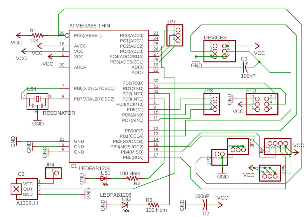
Schematic
FIG. H
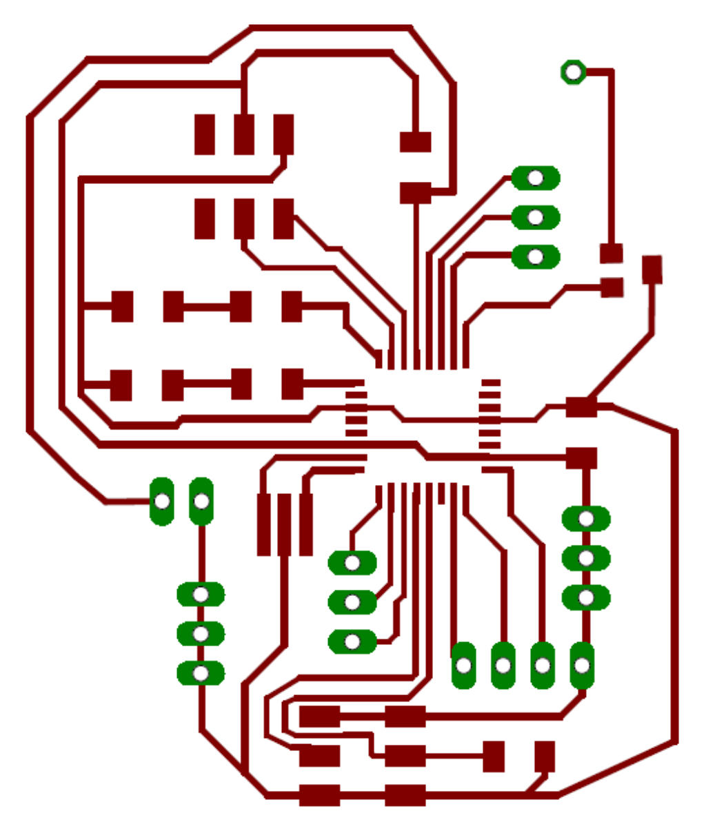
Board
FIG. I
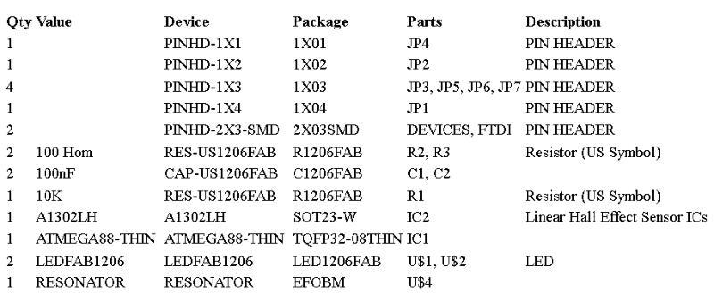
List Of Components
List of Components
FIG. L
Test of Final Project
Completed the wiring of all the components, the time has now come to test the Box Food Saver to see if it works. First we give power, connecting the plug of the power supply to the 220v home network (Italy). I close the drawer, the sensor detects the magnet on the edge of the drawer and sends a different value on the analog pin, this value is processed by the algorithm that starts the vacuum pump.To test the button, I press it and the software understands that I want to open the drawer, then the board sends the signal to the relay that opens the solenoid valve. At this point the air can enter the box and I can open the drawer. The software part works well and the hardware responds to commands.Wiring of components
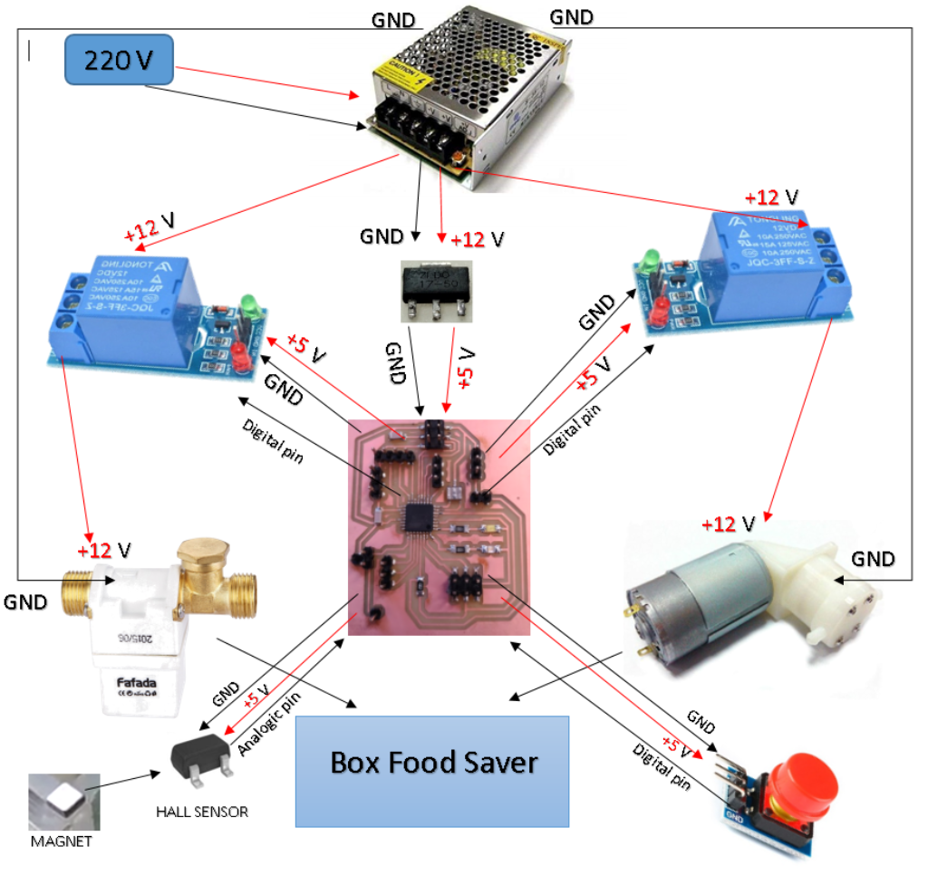
In order to simplify the wiring process I created this ideographic scheme.( FIG. N) . The components are clearly identified and also their interconnections. It is fundamental to remember that the electronic board receives current from the voltage regulator and NOT directly from the power supply because the voltage 12V would burn the board. The vacuum pump and the solenoid valve receive electricity from the relays and NOT directly from the power supply. The two relays and the button communicate with the Board via a digital pin. The magnetic sensor sends to the board the value detected by the proximity of the magnet, through an Analog pin.Voltage regulator from 12v to 5v
The power supply purchased for the project delivers 12v, this because the pump and the valve work at 12v. My board works at 5v and therefore it is necessary to reduce the voltage to avoid burns. At this point, the ZLDO 17- 50 voltage regulator comes into play. This small but ingenious component allows the card to work without suffering damage, and the output voltage that I detected with the voltmeter is very stable. The component has three pins, looking at it from the side that shows the written code, on the left we find -GND, at the center + 5v the reduced and stabilized voltage, on the right the input of the 12v voltage coming from the power supply.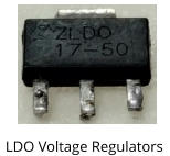
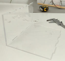
Problem to Solve
Despite everything seems to work, I realize that the closure of the drawer is not perfect, despite the silicone gasket. I tried to increase the pump action time, but it does not change anything. The evidence shows that air enters the Box. The problem is that air passes through the joints. This is a big problem, if the vacuum does not it's good, food preservation is also compromised.I tried to seal the joints with silicone and even with plexiglass special glue, but air continues to enter the box. The real problem is that even a very small space is enough to compromise the tightness. When I presented my project, Neil Gershenfeld suggested that I weld the joints by melting the plexiglass with hot air. This was a simple but brilliant idea. Unfortunately I could not implement this important change in my project, because after the presentation I moved to another country for work. As soon as I get the chance, I want to try and implement this suggestion and see if the problem is solved.Power Supply 220AC to 12V DC
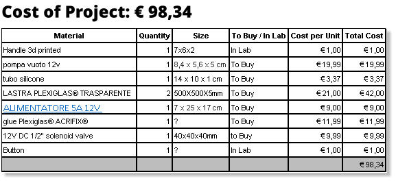
The power supply supplies the current to the board (via the voltage regulator), to the valve and to the pump (passing through the relays). For my project I chose this model.( FIG. M) The following are the technical characteristics: Input AC 110/220V. Output: DC 12V. Amperage: 5A. Power: 60W. L N GND = 110/220V Input -V +V = 12V DC Output +V AD J= Voltage fine regulation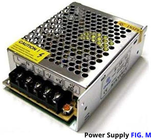

FIG. N
Final Conclusion
The project is certainly interesting and may have further developments. For this reason I decided to distribute my software (Arduino codes...) and hardware (STL, Eagle files...) components that I realized under license Creative Commons Attribution, in the NonCommercial- ShareAlike 4.0 International (CC BY-NC-SA 4.0) variant. This kind of licence allows anyone to share (copy and redistribute the material in any medium or format) and adapt (remix, transform, and build upon the material) my works, on condition to don't use them for a commercial purposes and to give appropriate credit, link the license and indicate every changes made.I chose this license because my project was born to reduce the waste of food, I think that this way is better and easier to improve the project and its diffusion. At the bottom of this page you will find the Zip file icon, simply click to download.
Creative Commons License
This work is licensed under a Creative Commons Attribution-NonCommercial-ShareAlike 4.0 International License.

Final Project Hardware
Giuseppe Allocca