Week 15 : Mechanical Design
- Make a machine, including the end effector, build the passive parts and operate it manually.
Fab Academy 2018 - Thierry Dassé
For this group assignment, we have chosen to make a roto molding machine.
This machine is usefull to make empty parts to use less material or to have a light piece.
Process is to put a low quantity of powder or liquid and to fix it to faces using centrifugal acceleration by rotating the mold.
By heating or chemical reaction, powder or liquid will become solid.
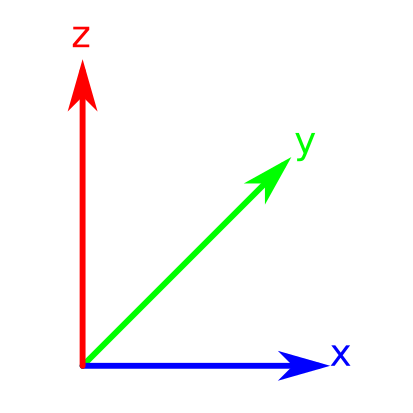
To have a good repartition of material, rotation usually are around at two perpendicular axis like x and z for example.
The two rotations can be done using two motors or one motor and transmission between first axis and second with gears and belt.
We want to try a more simple system with only one motor wich create x axis rotation and a second free axis. I believe that first axis
rotation can create second axis rotation because of gravity, low friction and system inertia. This second rotation can be chaotic
but I think it's not a problem for roto molding.
To create second rotation, we have two options. First is to add a mass on the frame to destroy symetry and move center of inertia.
Second is not to have a two perpendicular axis.
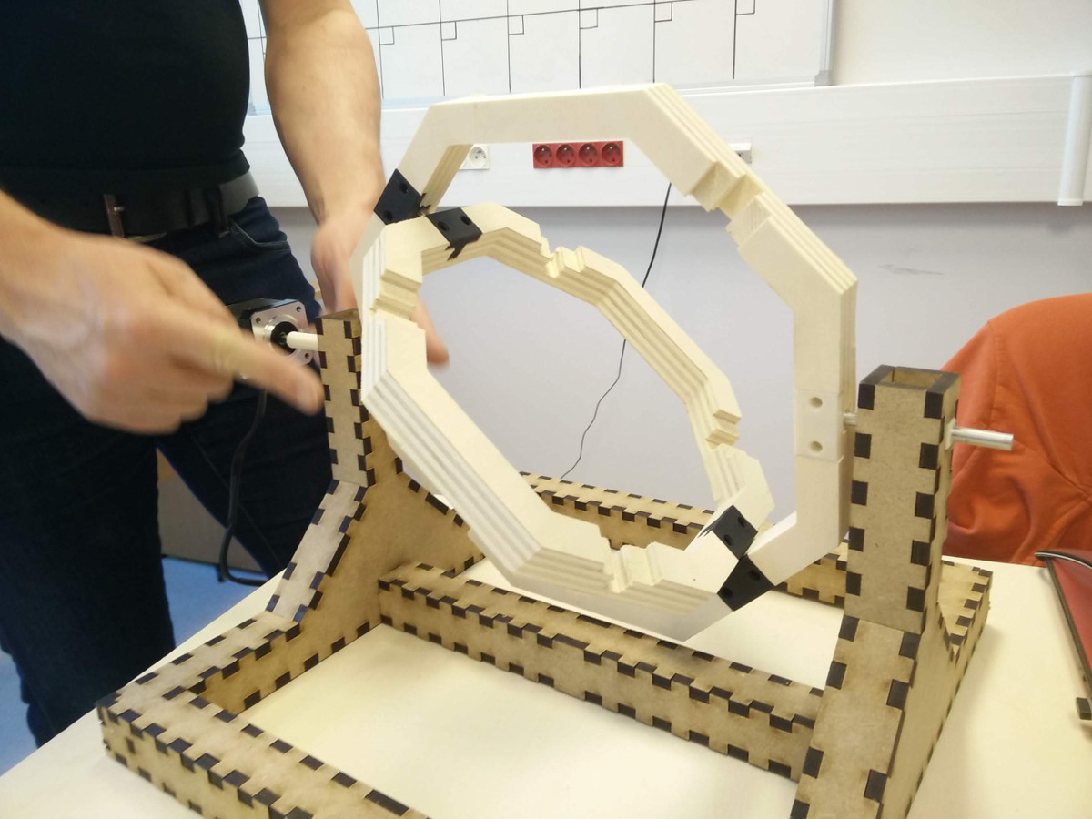
We choose second option and put our second axis 45 degrees from first axis.
After discussion about what our machine will look like, we divide work in three part. I was in charge of building a strong structure
able to carry two frames and a center mold.
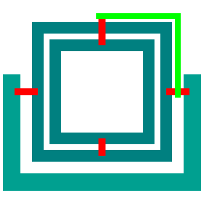
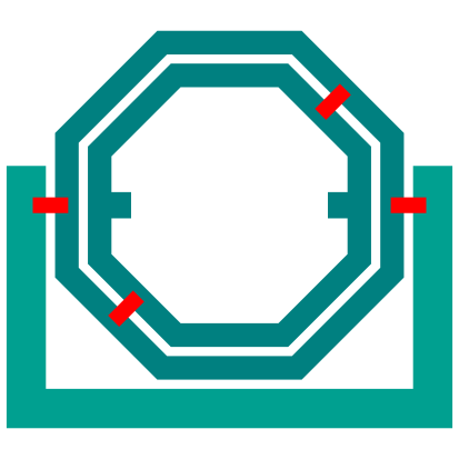
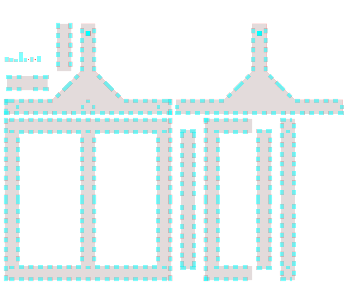
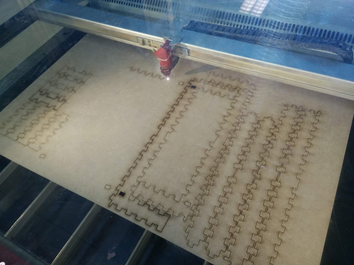
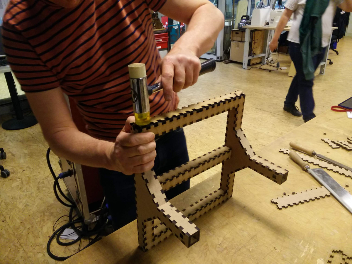
To be strong, I made machine base in square-section profile. I built this profile with 6mm MDF sheets using a laser cutter to cut parts.
To assembly parts, I made oversized slots to allow tight fit. I design slot sides with bezier curve for extra material to be only in the center part.
It's easier to enter and to go to slot back. With 0.2mm extra material, tight fit is very strong and parts won't take off. I had to assembly with a hammer.
0.1mm is enough to assembly a prototype you want to take off in order to modify.

Not to design all slots, I made one and clone it each time I need one.
Basic structure is 20 parts.
Structure
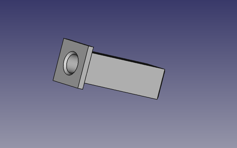
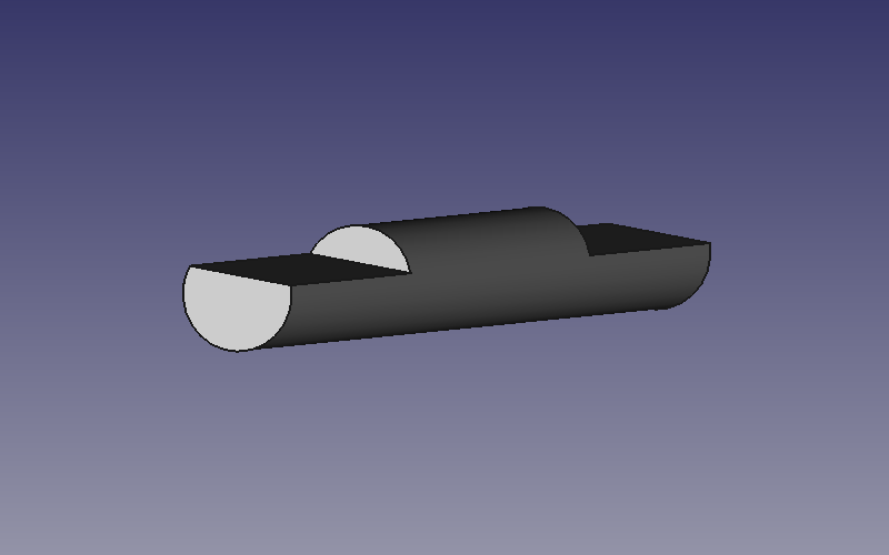
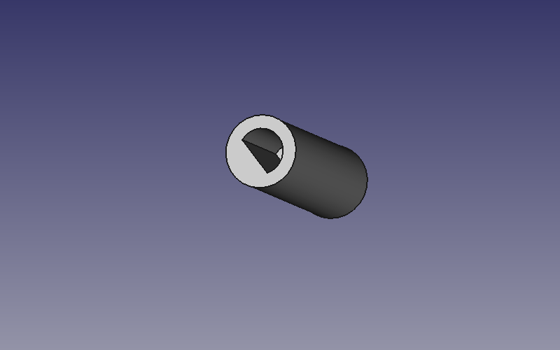
Structure axe (3D printing)
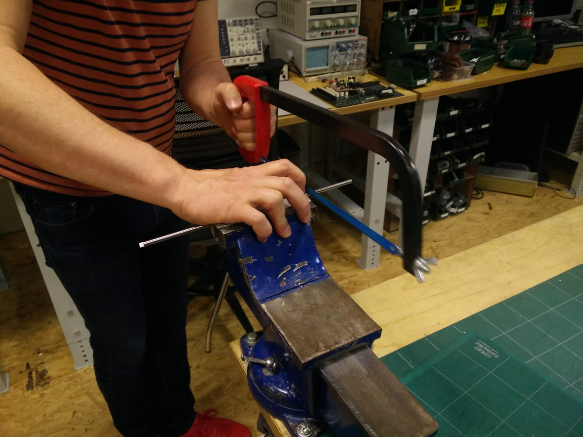
axe (aluminium)
axe motor (3D printing)
To move frames, we have chosen a stepper motor because we can easily control speed and turn slowly if we want to.
On first program, we send pulse to A4988 step pin each 10 milliseconds.
As Nema 17 is 200 steps a turn, rotation speed is half-turn a second.
/*
* Machine design : Rotomolding machine
* stepper motor constant speed rotation
*/
const int stepPin = 2; // A4988 step pin
const int dirPin = 3; // A4988 dir pin
void setup() {
pinMode(stepPin,OUTPUT);
pinMode(dirPin,OUTPUT);
digitalWrite(dirPin,HIGH); // set dir pin to high : clockwise rotation
}
void loop() {
digitalWrite(stepPin,HIGH); // send a pulse to step pin
delayMicroseconds(500);
digitalWrite(stepPin,LOW);
delayMicroseconds(500);
delay(9); // wait 9 milliseconds
}
With this program, second axis oscillate or reach a stable position but we dont have a good rotation.
So we decided to test variable speed on stepper motor.
To set smooth acceleration on stepper motor in order to force second axis rotation, I code a sinusoidal speed with:
delay(5+2.5*sin(0.031416*i));
where i is step number (between 0 to 200), 0.031416 turn step number to angle in radians, 5 is mean delay and 2.5 variation amplitude.
We tested different values and found that mean delay 4 and amplitude 1.8 are very good values to force second axis rotation.
/*
* Machine design : Rotomolding machine
* stepper motor variable speed rotation
*/
const int stepPin = 2; // A4988 step pin
const int dirPin = 3; // A4988 dir pin
int i = 0;
void setup() {
pinMode(stepPin,OUTPUT);
pinMode(dirPin,OUTPUT);
digitalWrite(dirPin,HIGH); // set dir pin to high : clockwise rotation
}
void loop() {
digitalWrite(stepPin,HIGH); // send a pulse to step pin
delayMicroseconds(500);
digitalWrite(stepPin,LOW);
delayMicroseconds(500);
delay(4+1.8*sin(0.031416*i)); // variable speed
i = (i+1) % 200;
}