Fab Academy 2018 - Thierry Dassé

Week 5 : Electronics Production

As outlined in the Commercial Boards policy, fabbing your own boards is an important part of Fab Academy. The ‘fabbest’ way to do this, is by milling your FR1 boards via Fab Modules or Mods.

Group assignment

characterize the specifications of your PCB production process

V shapes

There is two way to make a PCB, engrave or mill it and use chemical process. This week, we had to mill a PCB isolating tracks with a mill tool. To mill PCB, you can use a cylindrical tool with a very small diameter or a V shape wich is half a cone.

We found V shapes in the Lab but without any reference on it. It seems to be a 30° Vshape but we were not sure. So, I first wanted to verify V shape angle.
With inkscape angle ruler, I found 28°. As it can change if shape face is not perfectly horizontal, this V shape should be a 30°.
I calculated "diameter" for a 0.03mm cut depth and found a radius of 0.008mm and used this value in fabmodules to cut my board.
My board wasn't well cut. Reasons are I made a first mistake between radius and diameter and my diameter should have been 0.016. Second is that V shape is not sharp but round at the end. So, when you make your origin, your are not at triangle vertices. And third, there should be some vibrations
Vshape angle Vshape angle Vshape angle Vshape angle Vshape angle Vshape angle

Because, my board didn't work (see Generate traces and outline files), I decided to measure V sphapes "diameter" directly.
I wrote a file test wich mill only one line, one cm long (I read fabmodules generated files to understand how they are made before) :

PA;PA;VS4;!VZ4;!PZ0,200;!MC1;
PU100,100;
Z100,100,-4;
Z100,1100,-4;
PU100,1100;
PA;PA;!PZ0,200;PU0,0;!MC0;

Then, I took a picture of the result with a ruler. On Gimp , I measured than 1mm is 56px and linewidth is 27px. So, linewidth is 0.46mm.
Vshape linewidth

Generate traces and outline files

To generate my files, I first download png files here.
Next, I upload them in mods application.
On this application, I was able to calculate paths but not to save it in a .rml file.
My instructor recommends to use http://fabmodules.org/.
In input format, I first open fts_minitraces.png. Then, I choose Roland mill in outpu format and PCB traces (1/64) in process.
After that, I have to select the machine wich is SRM-20 for me and choose 4mm/s 0 for x0, y0, z0 and 2mm for zjog (height to move the mill without cutting) 0 for xhome,yhome and 2mm for zhome (this value is important otherwise the mill return to home at the end in the material and mill can be damaged).
On my first try, I put 0.03mm (group work) on cut depth and 0.008m on tool diameter with 4 offsets and 20% overlap.

The result was a bad board, because vshape real width is higher, it mills on paths and some of them disappeared.
I restart milling on monday, 19th with a 0.4mm tool diameter and 30% overlap (wich seems to be enough) and my board was fine.

http://mods.cba.mit.edu/ http://fabmodules.org/ http://fabmodules.org/

Make my PCB

I launch Vpanel for Srm-20.
I took a PCB board and put put double face tape on the backside and fix it on the sacrificial material.
Then, I did the XY origin first and the Yorigin with a multimeter. I took three Z point : bottom left corner, center and top right corner. I had a difference of 0.003 mm. To cut everywher, I chose z minimum.
Then I load my rml files and cut my board
After, I changed my Vshape mill to a 1.5 mm cylinder mill to cut the outline in 3 layers of 0.6mm.

Roland SRM20 Vpanel for SRM20 Board Double face tape Double face tape Change the mill V shape mill Search Z origin

Polarity

Zener diods and leds 
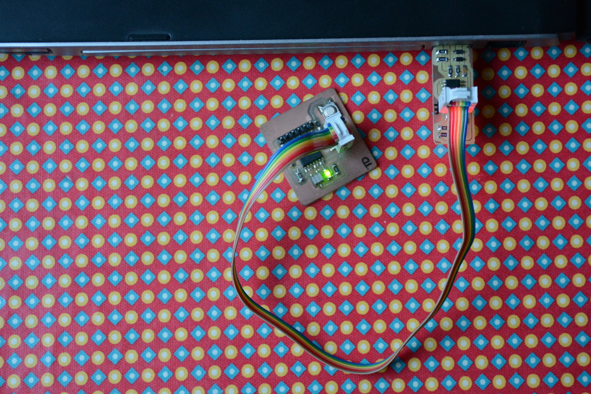
Some components aren't polarised so you don't have to take care on how to sold it.
But zener diods and leds are polarised. So I had to know where to sold cathode and anode.
Red and green leds are connected to resistor then to ground. So cathode must be connected to resistor. On led datasheet, I found that there is a T on led backside and cathod is on the character bottom.
For zener diod, there is a white line near the cathode pin to know how to sold it.

Source : https://learn.sparkfun.com/tutorials/polarity/diode-and-led-polarity

Then, I started to sold my board. To sold a CMS components, you first heat a pad, put solder on it, place your component on the pads.
When one pad is sold, your component does'nt move, then you can sold other pads. At the end, you can resold first pad to be sure solding is efficient.
I also add soldering on USB connectors to make them bigger and avoid float. After that, I verified all my tracks with a multimeter.

Soldering Soldering Soldering

Finally

After soldering, you'll have to program your board.
I've programmed mine with my instructor's one (He made it during his Fabacademy 2016).

Download fts_firmware_bdm_v1.zip here.
Then install avr-dude, gcc and make :

sudo apt install avrdude gcc-avr avr-libc make

Then extract the zip. Run a terminal in fts_firmware_bdm_v1 folder and type :

make

You will have a new file : fts_firmware.hex.

To program your ISP programer with another one, you just have to do :

make flash
make fuses

You can see if your computer see your new board by connect it and make :

lsusb

You'll have a new usb device : Multiple Vendors USBtiny

make flash make fuses lsusb

FabIsp as a programmer

You can now use your FabIsp as a programmer. For example, with the hello board (made in Week 7 : Electronics Design).
With Arduino Ide, In tools menu, select Board: ATTiny 24/44/84, Processor: ATTiny44, Clock: External 20Mhz (or Internal for board without resonator) and Programmer:USBtinyISP.
Then upload your program. I tried with a blink program with ledpin equal to 7 (pin number for input/ouput is on ATtiny44 pinout).

/*
 * Hello board programming
 * Blink on pin PA7
 */

const int ledPin = 7;

void setup() {
  pinMode(ledPin, OUTPUT);
}

void loop() {
  digitalWrite(ledPin, HIGH);
  delay(300);
  digitalWrite(ledPin, LOW);
  delay(300);
}

FabIsp as programmer ATtiny24/44/84 & ATtiny25/45/85 pinout

Slideshow

To see better images, I have done a slideshow on my website using javascript.
First, I created an hidden div

<div id="slideshow">
<span class="close" onclick="hide();">&times;</span>
<img id="slideimg">
<div id="caption"></div>
</div>

Then, I add css style to hide the div by default and show when clicking an image.

#slideshow {
display: none;
position: fixed;
z-index: 1;
padding-top: 100px;
left: 0;
top: 0;
width: 100%;
height: 100%;
overflow: auto;
background-color: rgb(0,0,0);
background-color: rgba(0,0,0,0.9);
}

After, I write two functions show and hide in javascript

function show(id) {
document.getElementById('slideimg').src = document.getElementById(id).src;
document.getElementById('caption').innerHTML = document.getElementById(id).alt;
document.getElementById('slideshow').style.display = "block";
}
 
function hide() {
document.getElementById('slideshow').style.display = "none";
}

Source : https://www.w3schools.com/howto/howto_css_modal_images.asp

Resize pictures

To create thumbnails or animated gif on what I did for my website, I need to resize pictures I made.
On linux, I found that I can use convert command in imagemagick package.
This package was yet installed on my computer. If not, you can do it by :

sudo apt install imagemagick

To resize a file is quite easy. For example, I want my picture width to be 1200px. In a terminal (Ctrl Alt t or better rightclick in file browser and open a terminal here),I did :

convert myfile.jpg -resize 1200 small_myfile.jpg

To resize several files, I had to make a loop.

mkdir sd
for file in *.JPG; do printf $file"\n"; convert $file -resize 1200 sd/$file; done

Then a copy of 1200px width pictures is done in sd folder.

Source : https://imagemagick.org/script/convert.php