Digital Drum
Digital drum is a modern electronic musical instrument ,In first I had a different thought about my final project for making a "RF signal jammer device" but going through Neil's input and output week I decided to make something very attractive with sounds and lights thats the Reason I chosed Digital drum ,I studied more about it because my concept was very different and unique I there I got some beat notes and I also tried it in my output week
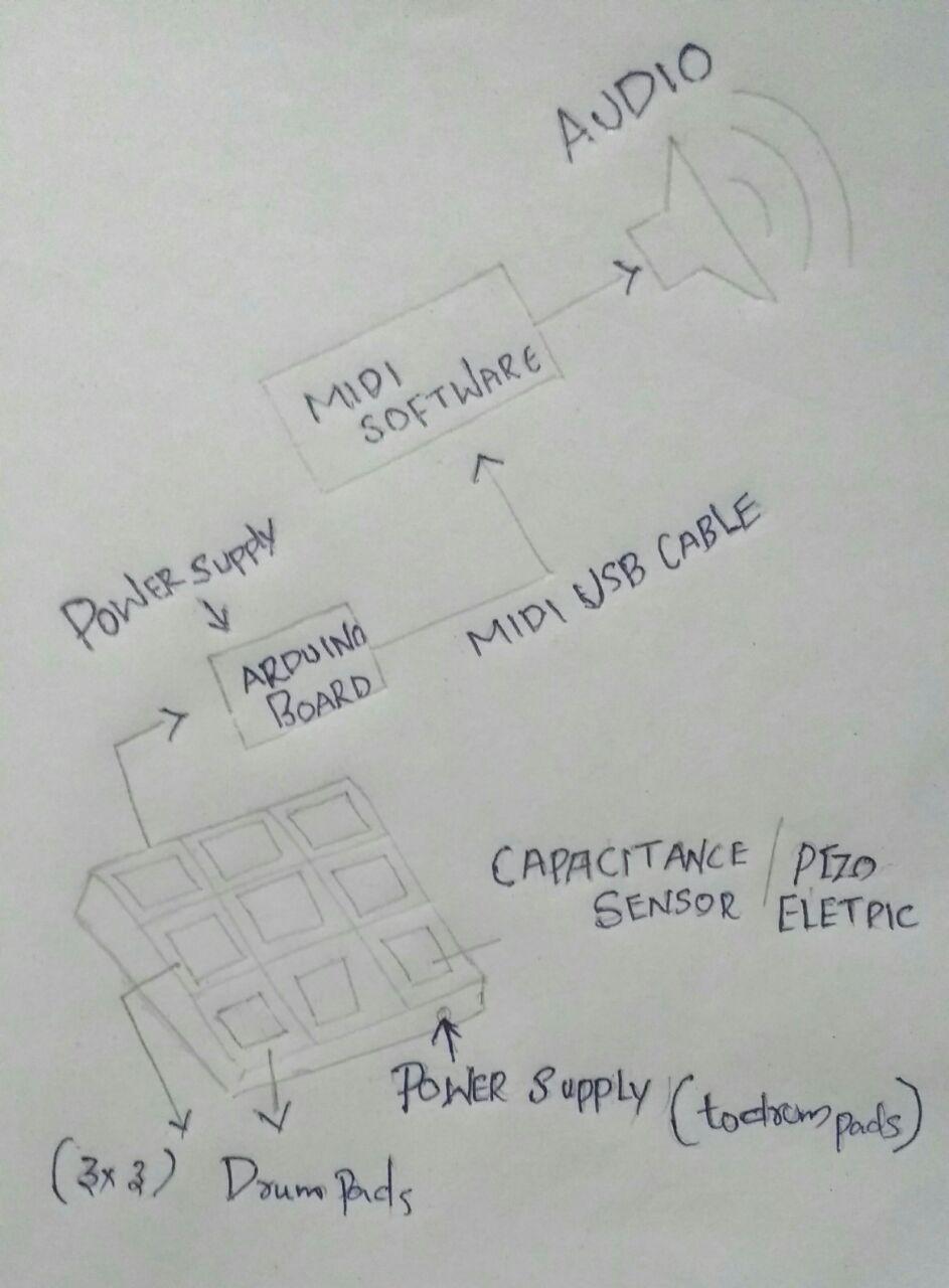
Flowchart of Working
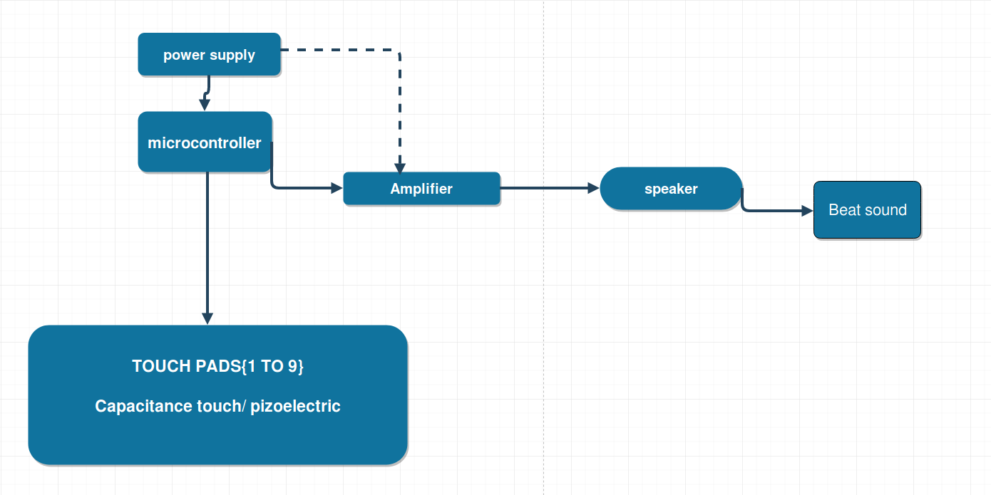
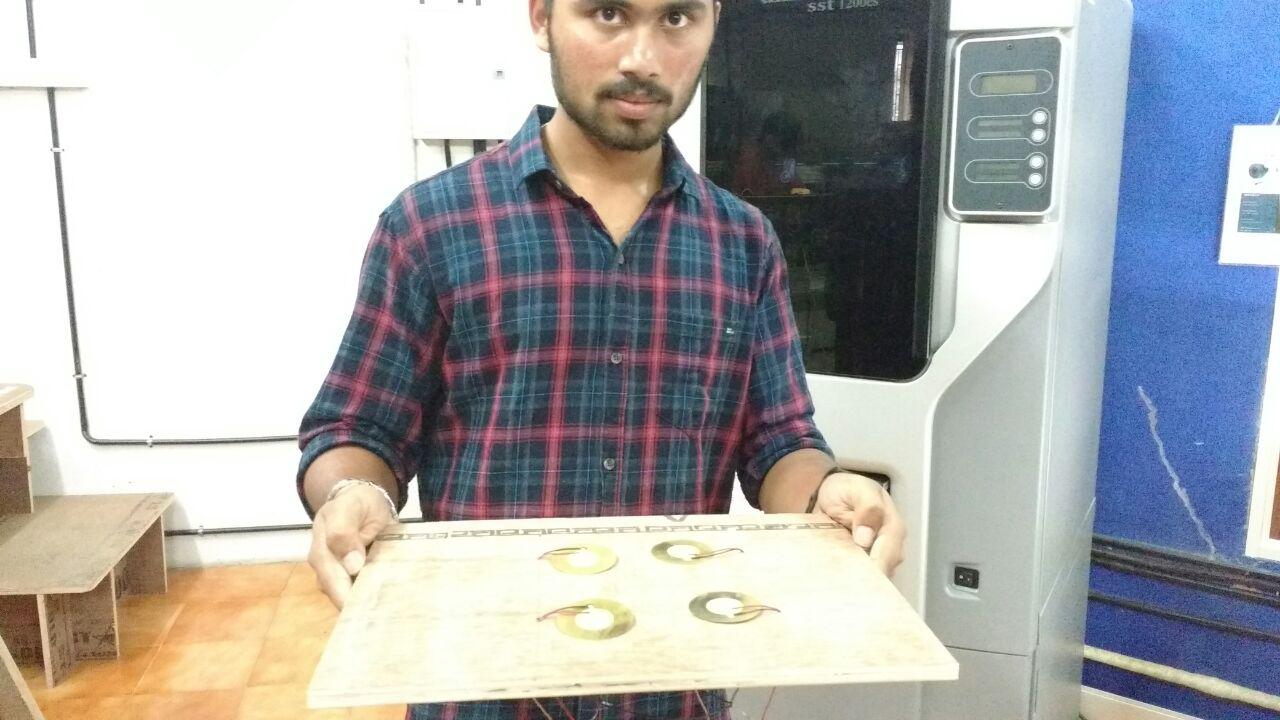
My idea is to make a box like thing with plywood and it have 2rows and 2columns in each columns are with capacitive sensor or piezo electric and filling with perticular beat sound when we touch to each of these shells The beat will comes out through the speaker
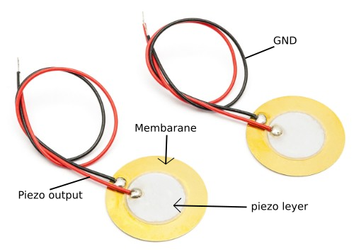
Sensor used
In our lab has piezo electric sensor so I decided to go with that Its seems very easy to work with I got some information about piezo electric from my instructers and some from web also "here the piezo electric has two layers when pressure applied between these layers an electric current is produce ,we can make this output puls as use for us "
WORK FOR PROJRCT
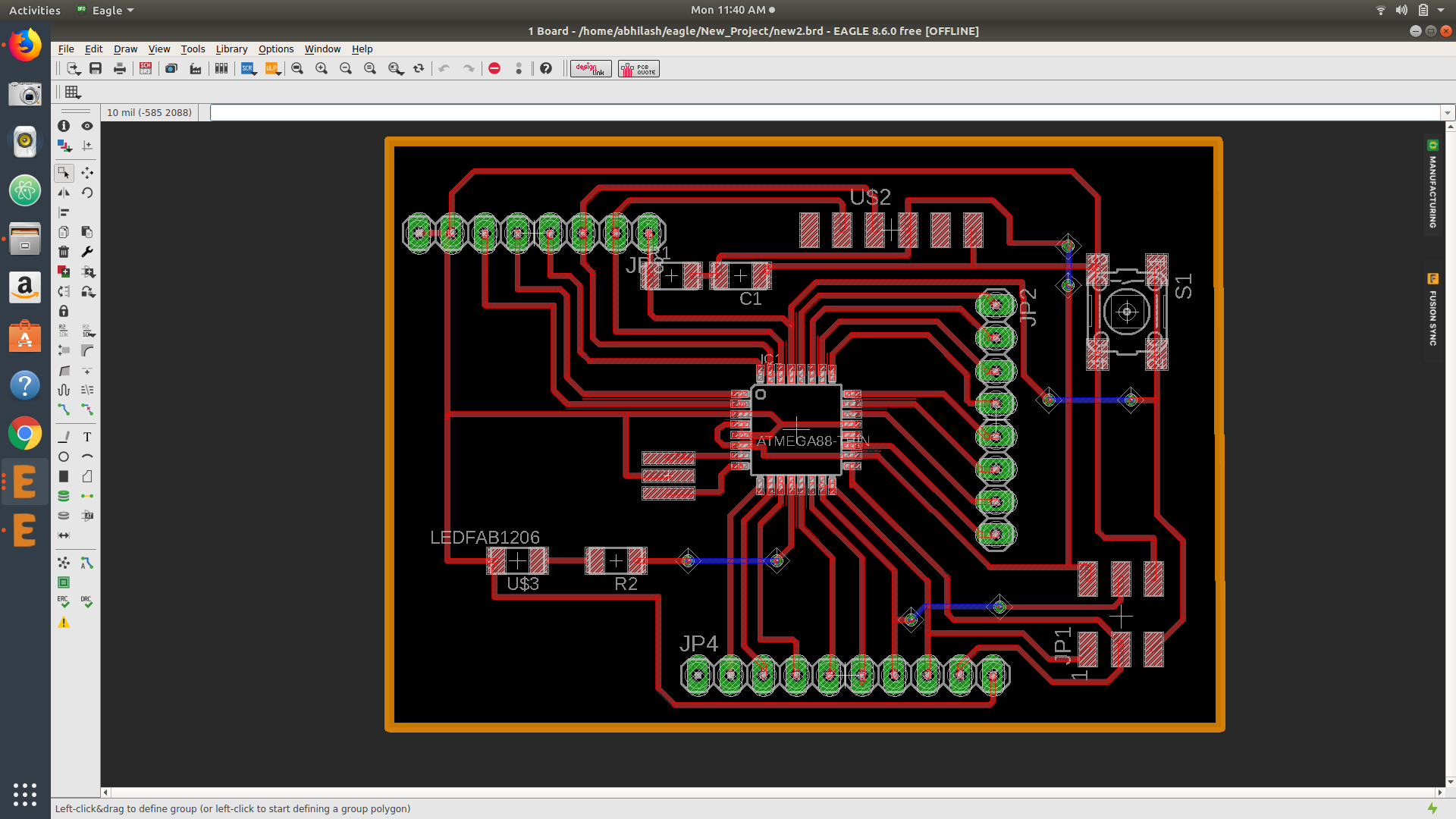
To start my work with the project I realy thinked about from which part then I decided to start with most toughest part designing of my board ,Because I want a atmega board with maximum outs not only for this project and for future also so I started from "Electronic design & production"
Electronic design & production
Through the weekwise assignments I just grab some time for designing a PCB with ATmega328p for my project I think it will help me to give more time working with the programing and all
It very difficult were designing with Atmega I faced all the problems bt most of
I tried with manual routing it takes more time for the designing but I think it save my time from the project weeks
I take out maximum pins from the microcontoller that was my aim ,not only the project I can use this board in future also
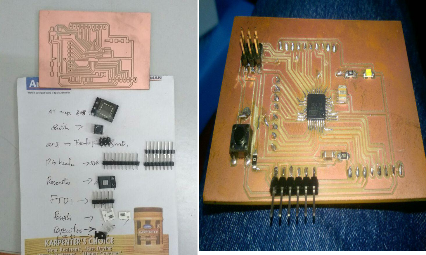
My components are;
1.ATmega328p
2.8mhz Resonetor
3.LED & 499 ohm Resistor
4.FTDI & SMD header
5.1mf capacitor & 10k resistor
6.Omron switch and pin headers (2*4 & 2*5)
.sch file of board
.brd file of board
Then I take 7*5 PCB board from my lab I think it seems as almost same with lenght and width of my design so I machined the trace part on that board in Roland milling machine by exporting the trace by giving the monochrome selecting front and pads ,
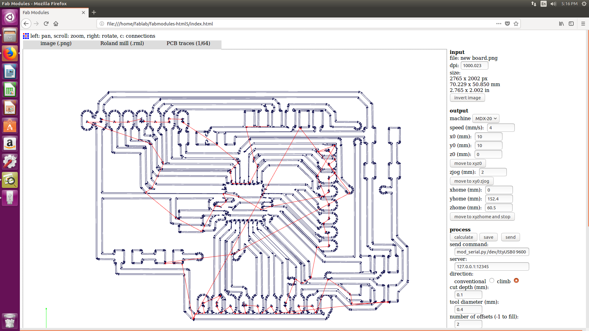
Here I used the 1/64 bit for trace in the above image shows the default settings I only changed the offset because the default offset cause some break in the trace so I reduced it into 2 the I milled my board out and solderd with the components that above mentioned ath the right way
Testing of Pizo electric
My next step was to find the threshold frequency of my piezo electric weather only I can make the bass beat in perfect way for that I cut out a cardboard piece (like the pad I am going to use) and then I attached piezo on it
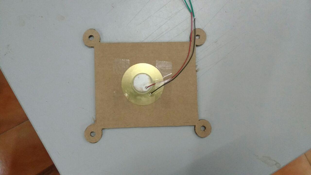
Then I connected the piezo to the board that I milled I tried with a programme for testing the piezo after uploading that programme I tested the threshold frequency using the serialplotter in Arduino software by putting the baurdrate 57600.
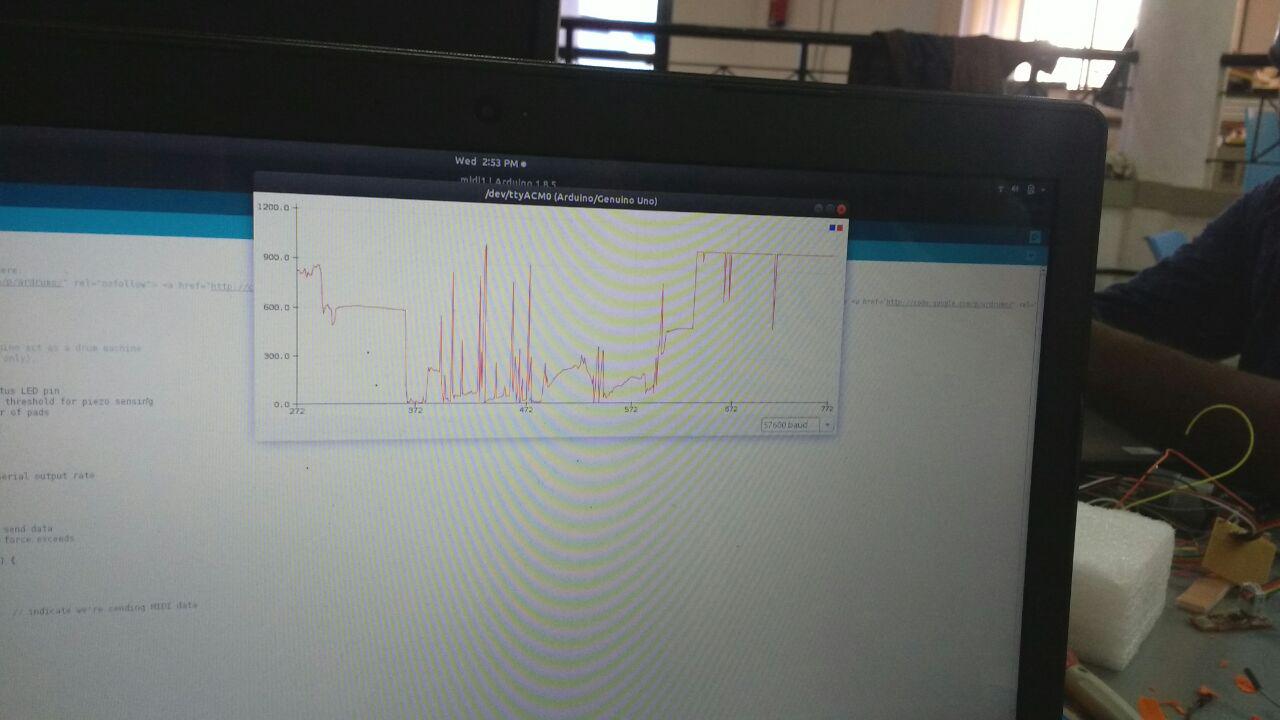
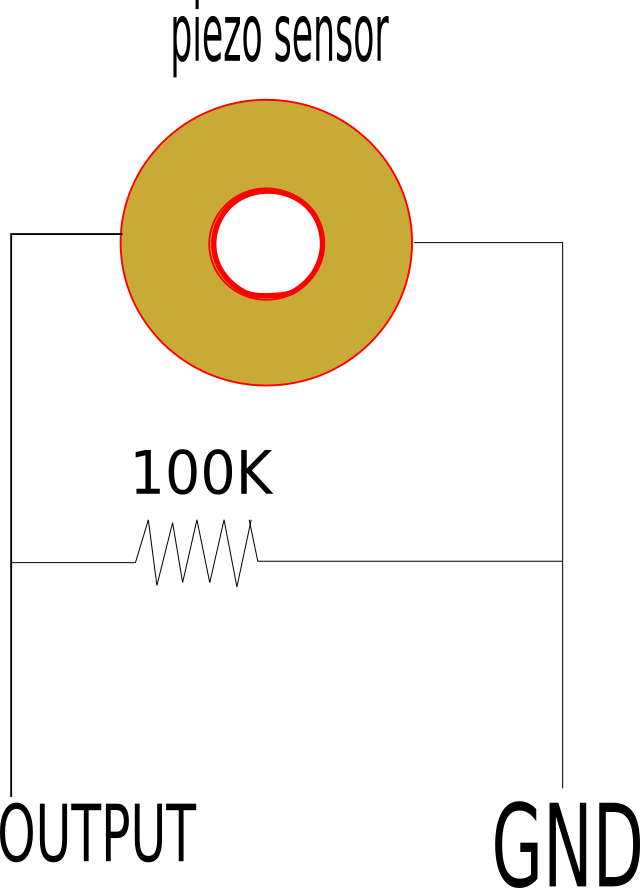
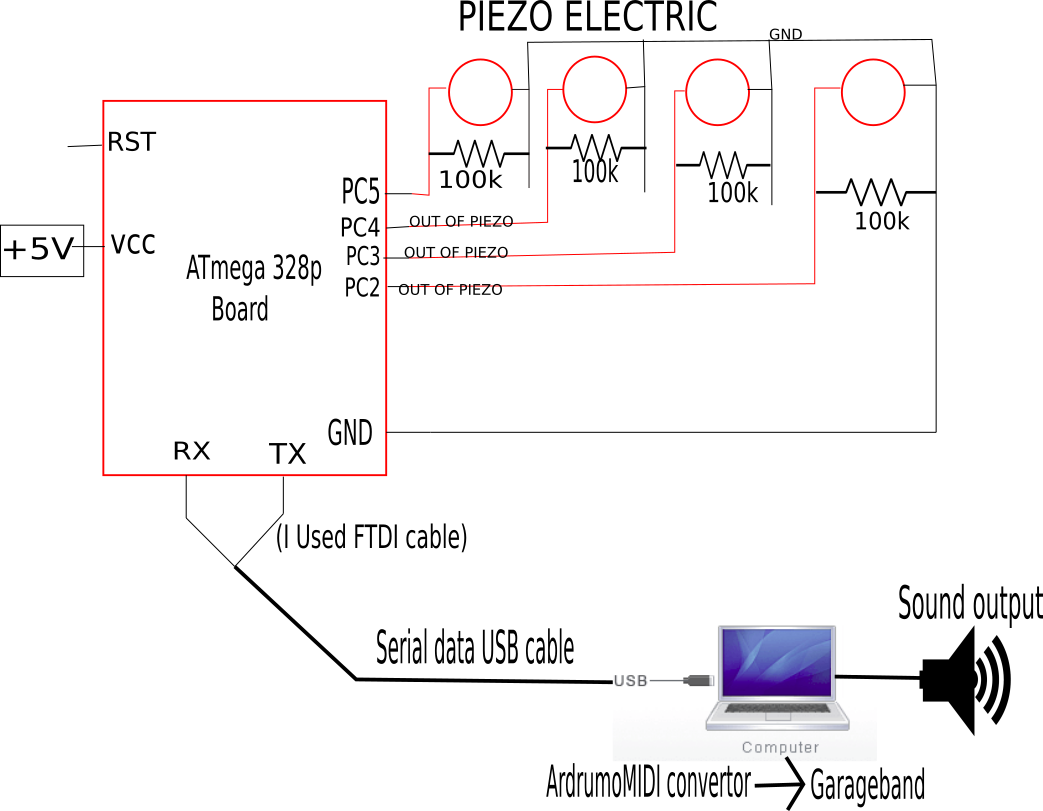
But here I felt the same range of frequency at a different level of touch ,The drum beat sound have the variation the sounds that is the main atraction for making the output puls like that I put an 100K resistor across the pin out from pizo electric (it only causes a change only in electrical resistance, not in electric potential.) .I decided to put resistor for the each piezo I am going to use like the below connection
CNC-plywood cutting
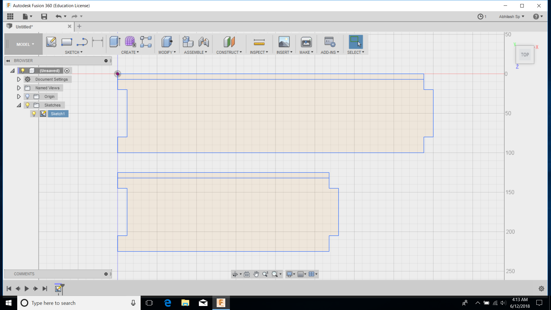
After the testing of the piezo I decided to draw the body of the drum . Dsifferent design passes through my mind eventhough I fixed a simple design to go with for that I draw a a four side frame in fusion 360 ,that wasn't very complicated one som I decided to go with a 2D design on fusion .I already worked with fusion before so I seeems very easy to draw the frames on the fusion also I want a small pocket on the walls of the frame so for that I made a closed loop at the top,Here I mostely used the line tool for the drawing
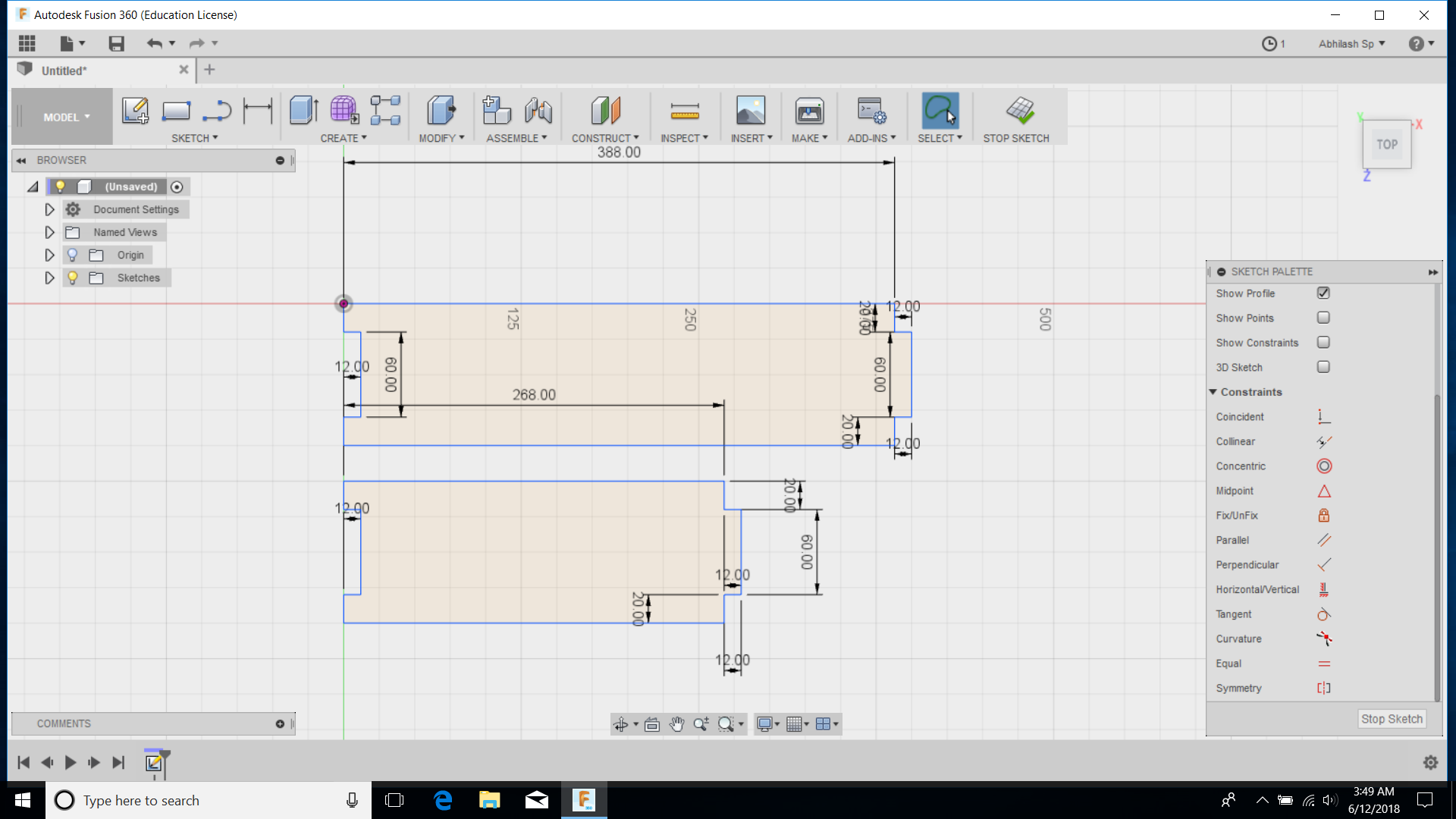
Finishing my skectch the I exported it as .dxf file the open it into the V-carve I used 4mm dia tool for the cutting of my frame before makeing the G.code I made all the line closed using select tool and Group tool The made the part to cut through "showtoolbar" the make cut, here I selected the tool and added tab through "Edit tab option" ,after editing all the that I want make some option as defult then saved the toolpath for generating the gcode
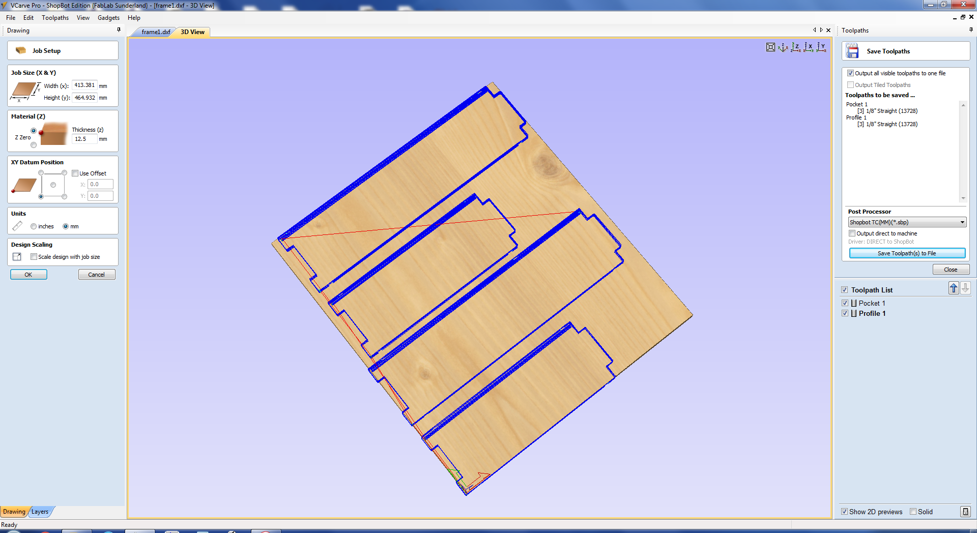
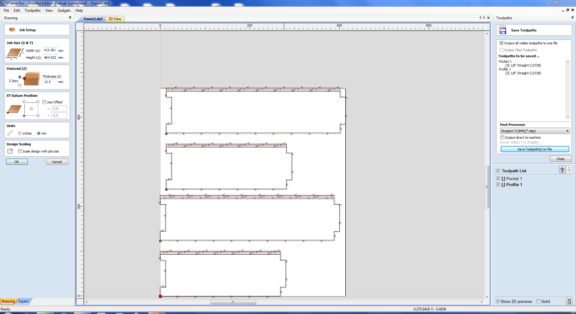
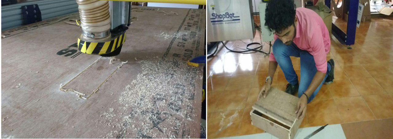
After Giving the orgin I beagn to cut Here I got a small plywood piece from the waste material I think I can place that one above that frame for that I draw the frames with measuring that Diamension after cutting from shopbot I just arraigned the parts I gives me good body
DXF Here the .dxf file
G.code Saved toolpath
Wire connection for piezo
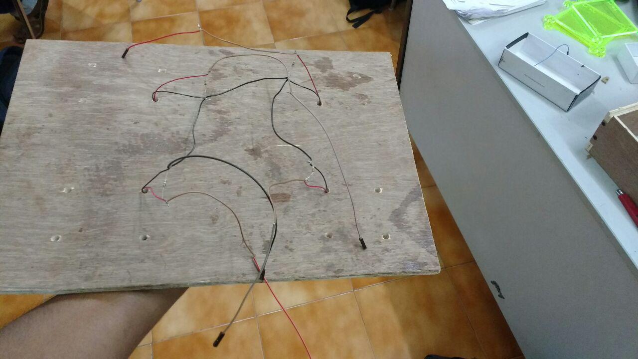
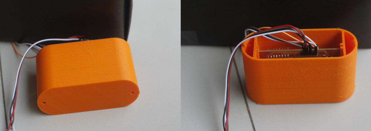
My next step was making the wire connection in a possible manner with very neat nad clean .It was earlier in my mind thats why I made the body as a box manner so I can fix my board and wires inside the box it shows more neatness. For that First I drilled the pice that I attached on the frames here I ready to go with 4 piezos so each piezo wires I taked through the drilled holes that will reduce the view of my wire from front
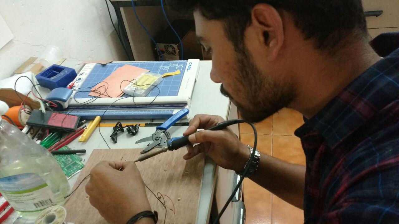
I put a 100k resistor for each piezo that I showed before in the connecting diagram ,I took all the ground wire as single can attach a single ground pin of my board then I took the out pins of piezo each one singly ,the soldering was some difficult attaching each of them at a single point but I was very nice after soldering
Here below is the connecting diagram of the piezo ,board ,and to pc I connected the out of the piezo to the pins of PC5, PC4,PC3,PC2 of my ATmega328p board and to the GND and I used FTDI as my serial data senter to pc
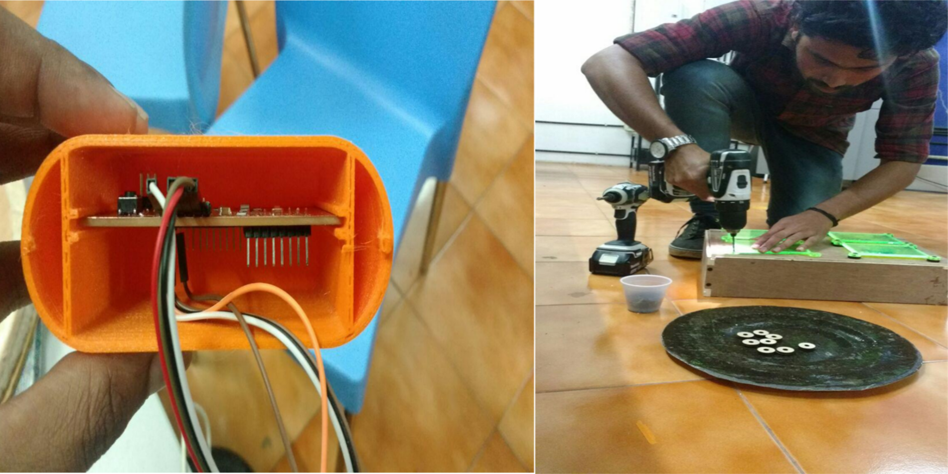
3D Printing
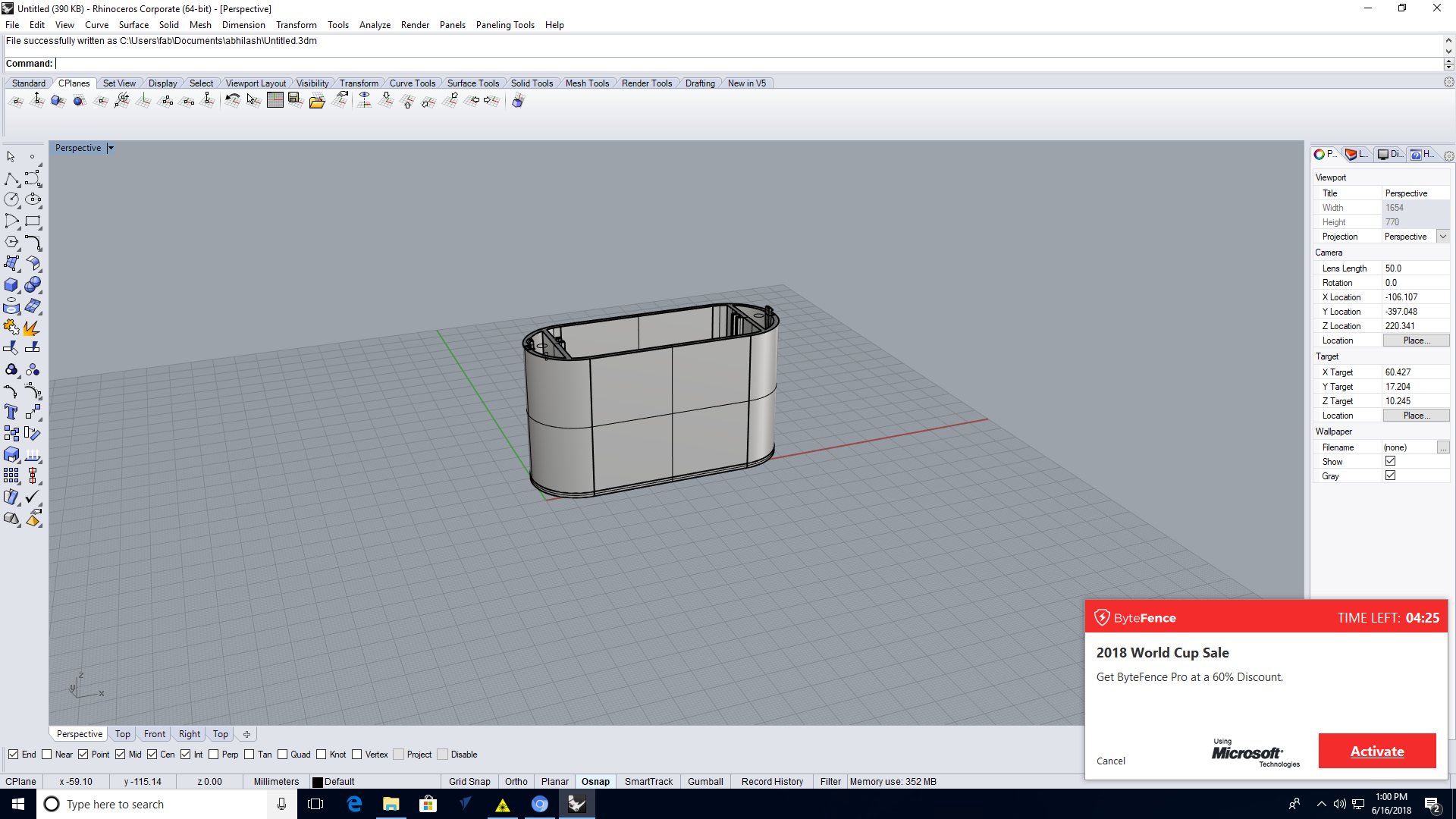
I want to attach my board inside that box I dont see any other way either making a case for my board that idea brings me to make a 3D printed case for fixing my board .I solderd my board in very unique in my board there has pin headers in both the direction so the box like structure will not possible so I decided to draw my case like inserting the pcb into it from center.I opend "Rhino" software ,Rhino is an user friendly software
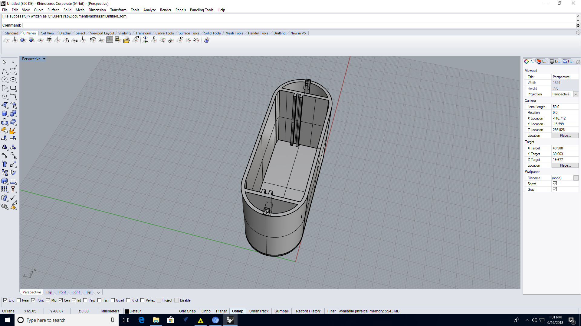
Ultimaker 2 is the 3D printer in our lab I opend the .stl file on cura for making the G.code after opening I gave the layer height as .15mm and balance is default it cause 6.30hr so I put it for print at night

I got a fine printed case on ultimaker , The layer thickness and and fill density was very fine so I got a rigid case with maximun strength then I put my board into the case
STL Here the .stl file
RHINO FILE.3dm file
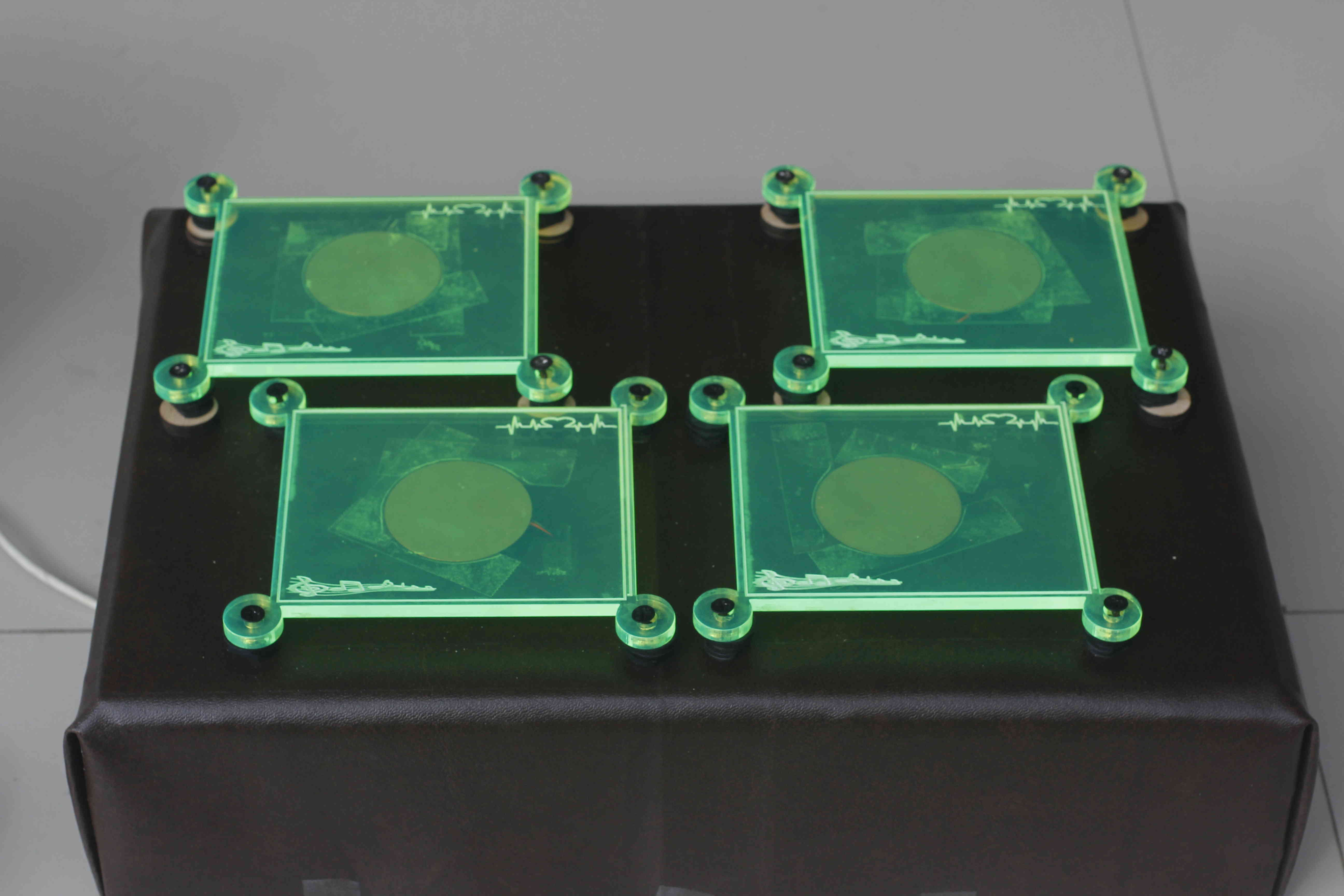
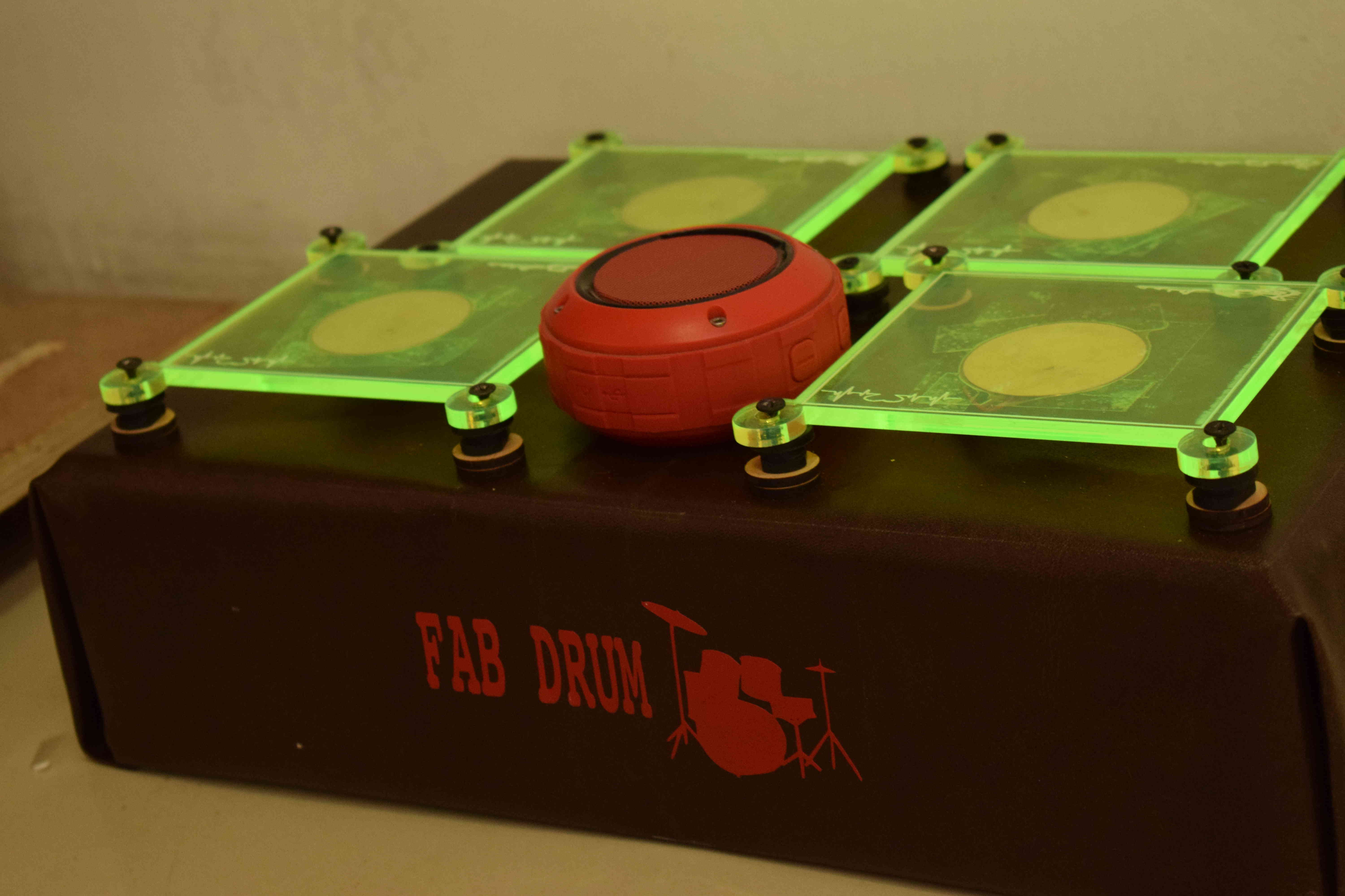
LASER CUT
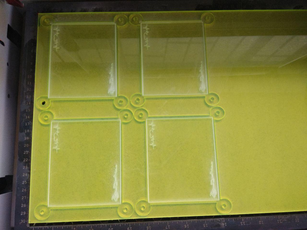
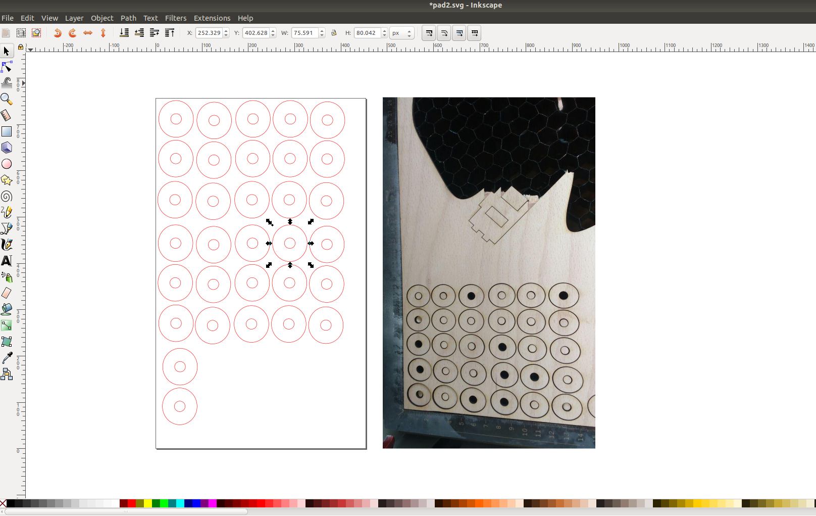
I want to make 4 pads for attaching the 4 piezos I decided to make that pads in acrylic ,In our lab there is 6mm fluresent acrylic it can make the pads very attractive for this I selected laser cut I drawn an vector image on inkscape like a rectangle structure then I bitmapped two sticker above that pads for engraving it makes that pad more attractive
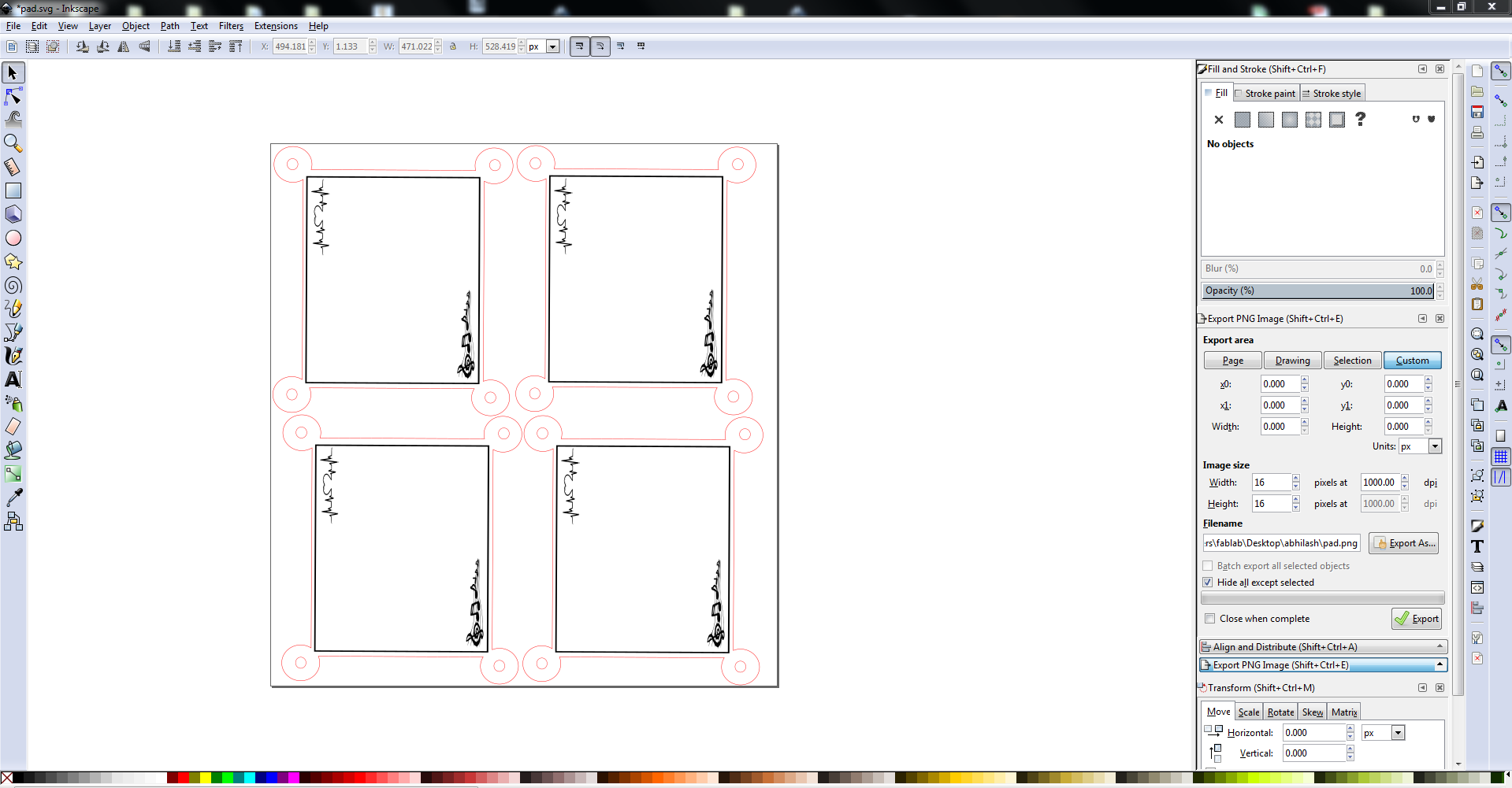
Then give stroke paint red for laser cut and black for laser engraving then I gave print ,In our lab have trotec laser cutter then I opend the software and give the material that I selected the give the print
Also I want some bush for giving height to my pad for that I selected a waste plywood that already some one used I designed some bushes with diamension of the end of the pads
BUSH .svg file
PAD.svg file
Programming and Softwares Used
It seems very difficult to work with some midi softwares in windows and linux after lot of searching and trying I found a software "ARDRUMO" in MAC OS it is very easy to work with and I got somany tutorials from instructables also,we can simply load the sketch to our board for each serialdata from each port of my board can controled in ardrumo software,"Here Ardrumo is acting as the serial to MIDI convertor" and after that there is a fully equipied musical software "Garageband" ,just open it and connect with the midi convertor Ardrumo. Also we can select different sounds for each singly occupied port that makes this software more friendly (for windows we can use "HAIRLESS" software as midi convertor )
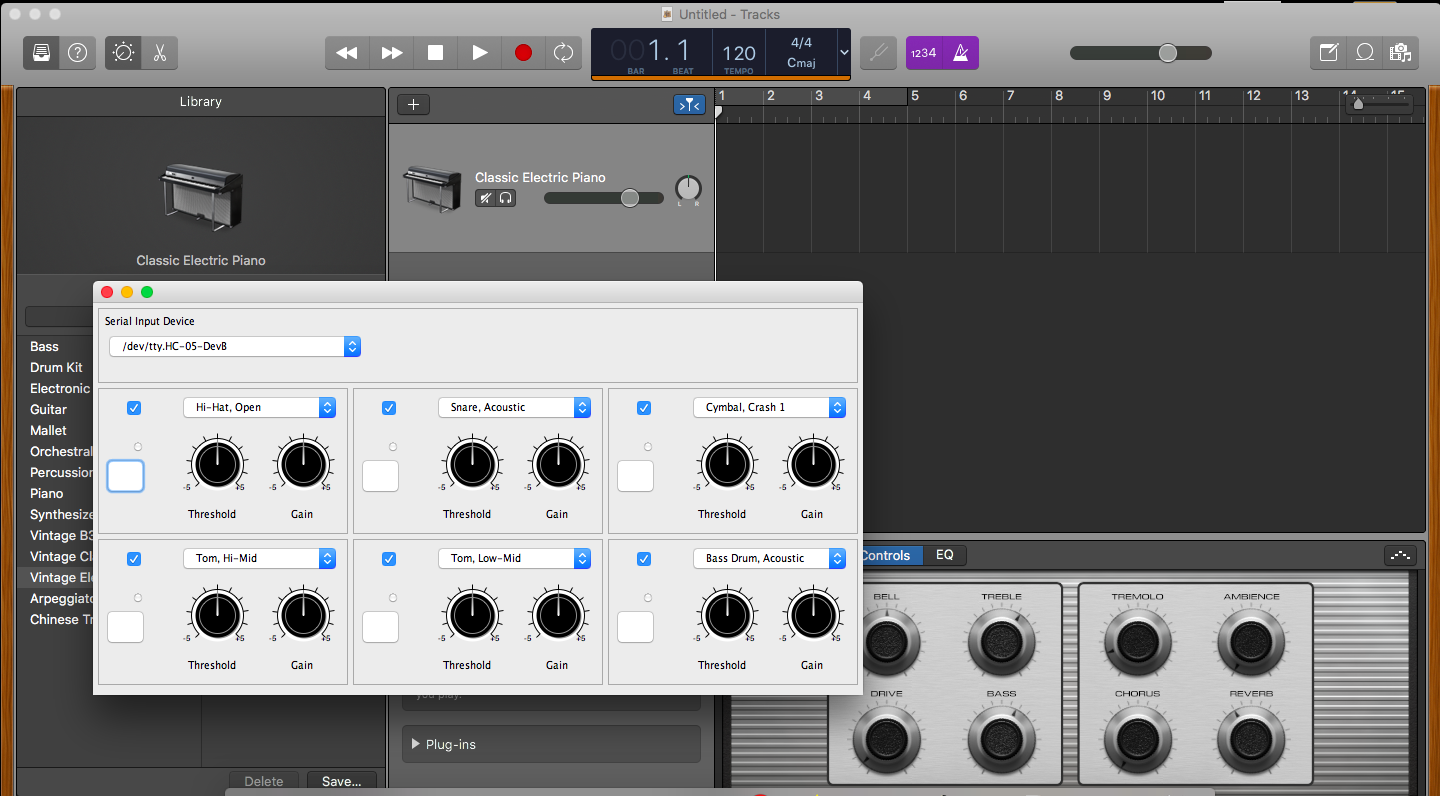
We can connect out board to the pc by a serialdata transmitting USB cable here I used the FTDI cable as my serialdata transmitter in Ardrumo we can select the input device that we connected ,through this the data starts to sent to the ardrumo ,the ardrumo makes the sound from the pulse that comes from the selected port.we can change the sound on ardrumo as we likes
Programming
In the programming part it doesnt seems more difficult
you can see my programme below , I used arduino for writing the programme for my board I used the board ATmega328p I already loaded the board spec on my board manager in arduino
https://raw.githubusercontent.com/carlosefr/atmega/master/package_carlosefr_atmega_index.json using this link you can also load the specification of ATmega328p to your arduino ,after adding this link to the preference install "Barebones ATmega Chips"
from Board manager.
#define PIEZOTHRESHOLD 5 // analog threshold for piezo sensing #define PADNUM 4 // number of pads #define MUL 40 #define DIFF 2 int val; int drum_val[PADNUM][2]; int temp1, temp2; void setup() { // pinMode(LEDPIN, OUTPUT); Serial.begin(57600); // set serial output rate } void loop() { // Loop through each piezo and send data // on the serial output if the force exceeds // the piezo threshold for(int i = 0; i < PADNUM; i++) { drum_val[i][1] = analogRead(i); drum_val[i][0] = i; /*if( val >= PIEZOTHRESHOLD ) { Serial.print(i); Serial.print(","); Serial.print(val); Serial.println(); // digitalWrite(LEDPIN,LOW); }*/ } for(int i =0;i < PADNUM;i++){ for(int j =i; j < PADNUM;j++){ if (drum_val[i][1]< drum_val[j][1]){ temp1 = drum_val[i][0]; temp2 = drum_val[i][1]; drum_val[i][0] = drum_val[j][0]; drum_val[i][1] = drum_val[j][1]; drum_val[j][0] = temp1; drum_val[j][1]= temp2; } } } for(int i=0; i < PADNUM; i++){ int dif = drum_val[0][1] - drum_val[i][1]; if((dif < DIFF)&& (drum_val[i][1]>PIEZOTHRESHOLD)){ Serial.print(drum_val[i][0]); Serial.print(","); Serial.print(drum_val[i][1]*MUL); Serial.println(); } } //delay(10); }HEREyou can download the programme
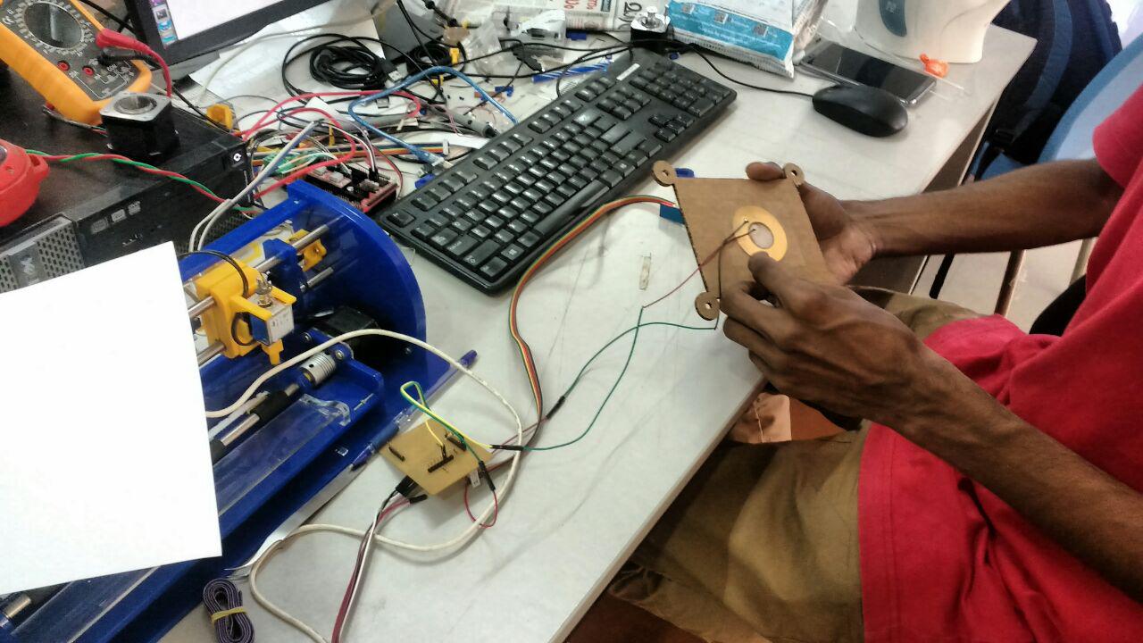
First Testing
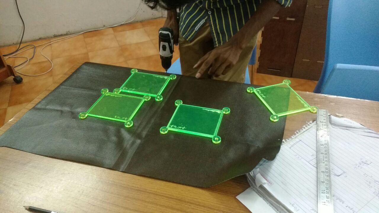
After all the arraignment I just think about a trail insted going to finish all my work so I connected and arraigned all the parts and drilled the pads also but after drilled I felt some vibration also so I decided avoid that variation because the piezo can sense a small amount of vaibration it cause overlap of sound so I used a cotton cloth for my trail if I win I can use this type of material to avoid vaibration
Here is the testing video of my fab drum, in the video you can saw the breather cloth that I used to avoid the vibration
I felt complete with out any vibration and noise that makes me to think about add something to my model to avoid the vibration like some thick cloth because here I used beather cloth in our lab it reduced the vibration very much,Here I got an idea from My instructor "Yadu sharon" use some rubber bush in between the bush that I cut out from waste plywood and also use some rexine cloth
Here I went a shop for purchaising the rexine cloth and rubber bushes that I want and I got it from near a shop from our lab ,after buying the material that I want I rearraigned my model with that you can see in the below images
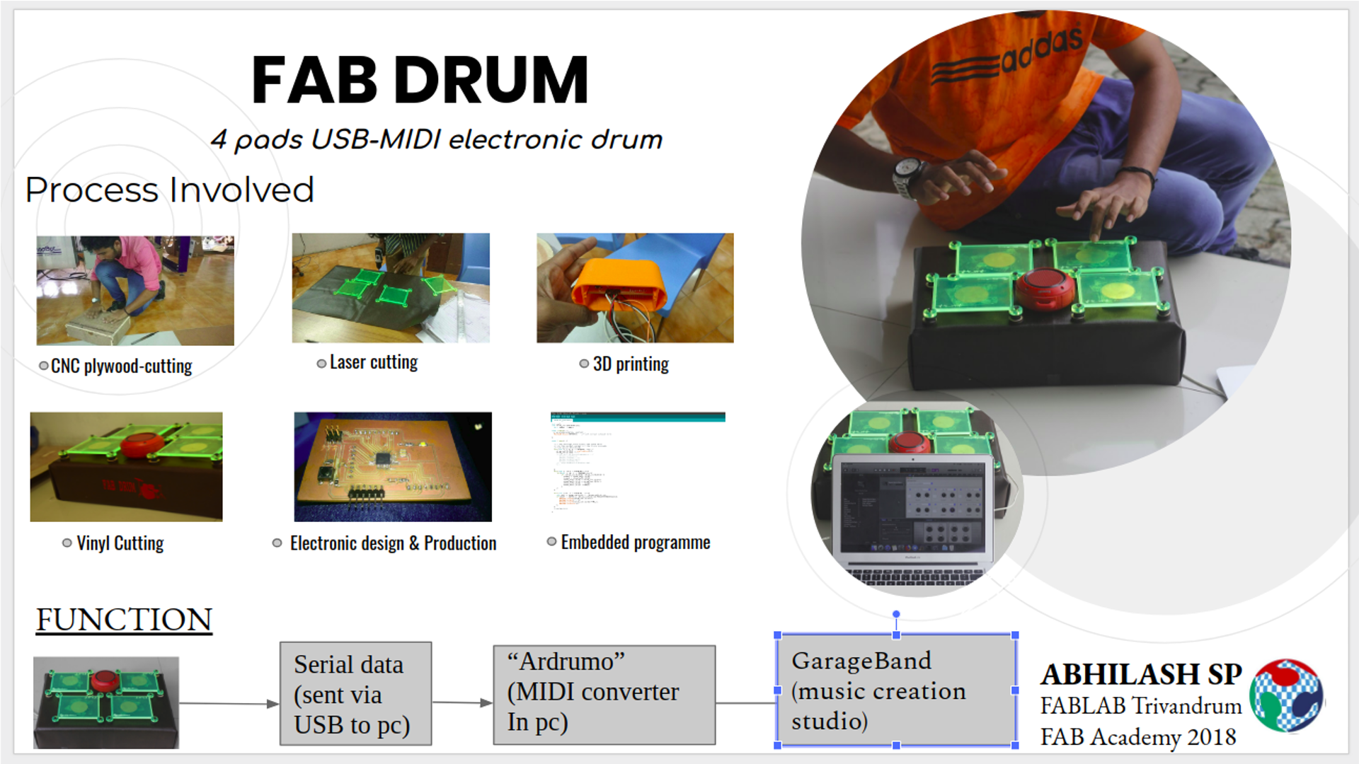
Final Presentation with Neil
Our lab's presentation was 19 th june so we were busy with our presentation slides and video. There is already mentiond on the fabacademy Schedule for presentation with Neil prepare drafts of your summary slide with resalution 1920x1080 and make a video clip with 1080p less than 10 mb and 1 mins .I made the slide and also video it was a very special moment to me at the time Neil said it is a nice project you can see the slide and video below that I created for presentation
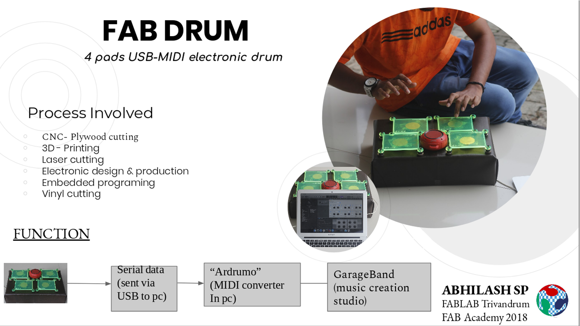
In the global evaluation process my evaluator Nuria Robbles instruct me to change the slide by "Add pictures of the processes involved in the final project instead of text" ,Then I edited my slide like her instruction and made a new presentation slide
HERE you can see my presentation.mp4 for Neil from this link
Final video of working
Here is the working video of my FABDRUM
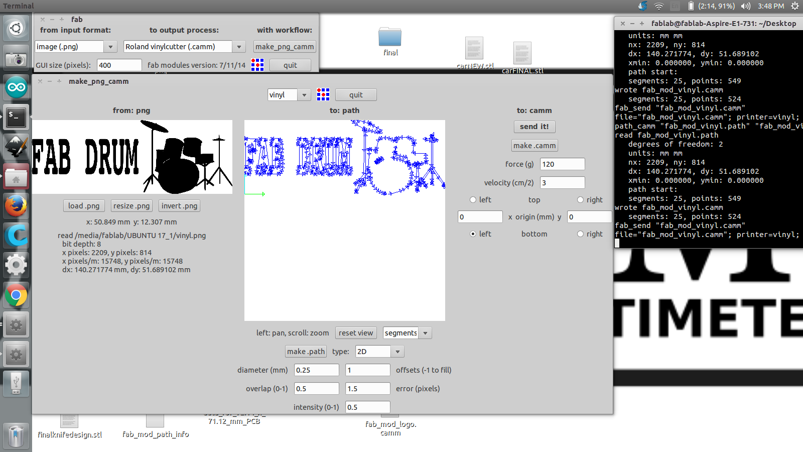
vinyl cutting
After making my FABDRUM i think I want to sticker the name to my DRUM kit so I decided to go with vinyl sticker I created my sticker using INKSCAPE software I just texted a name and bitmapped an image for making that sticker so attractive .After making the design I exported it as .png and open it in the fabmodule for vinyl cut after open the PNG image I gave the fore= 120 & velocity =3

After making my sticker on vinyl I just cut the piece and attached it to my FABDRUM as a a label and it seems very attractive when vinyl stiker makes stick using masking tape on my drum kit.
.SVGyou can download the .svg file of the vinyl cut
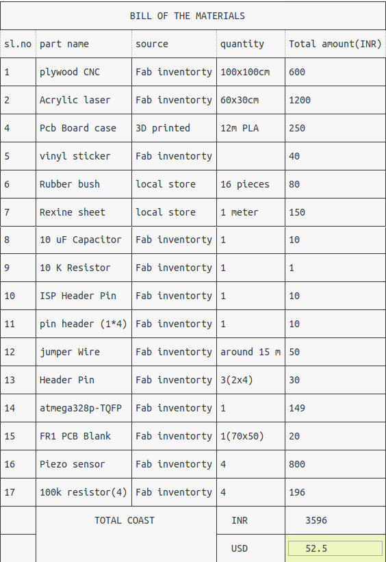
Bill of the material
For my project I got most of the materials my lab ,I only wanted to by rexine cloth and rubber bush from a local shop I calculated each components I used by taking the the cost from online and the calculating the amount I used you can see the BOM of the components that I used in my status
License
This project is licensed under Creative Commons
References
http://todbot.com/blog/2006/10/29/spooky-arduino-projects-4-and-musical-arduino
http://www.instructables.com/id/MIDI-Arduino-Drums/
