Week 11:
Input Devices
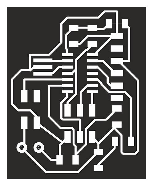
Board design
The final project of mine requires movement sensing and that lead me to choose the ir phototransistor sensor for the assignment.
First I was thinking to choose ultrasonic sensor for measuring the distance, but later on and because this type of sensors needs no barrier to give an accurate read to the correspondent body and my final project which a coffee table have an acrylic sheet that interfere the read of the sensor.
Sensors that I tested are:
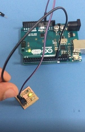
Hashim suggested me to check the sensor before I cut the board using the Arduino and then using my board which only included a (2x2 Pin Header, IR Sensor, led, resistor 1K, resistor 10K) the original design from the assignment page to practice.
- Making a board without Attiny 44 to test the efficiency of ir sensor read with LED -
Testing time
Sensor 1
So I connected the board to arduino first
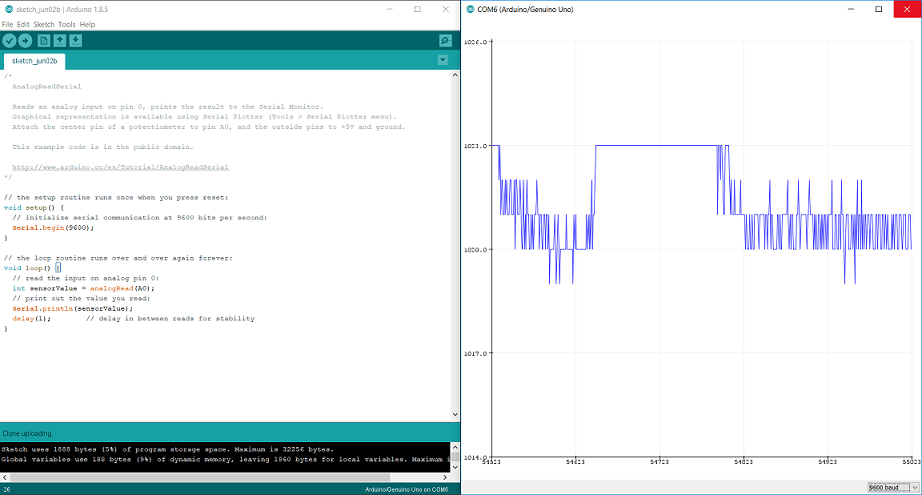
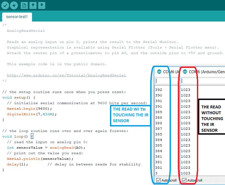
Serial ploter read
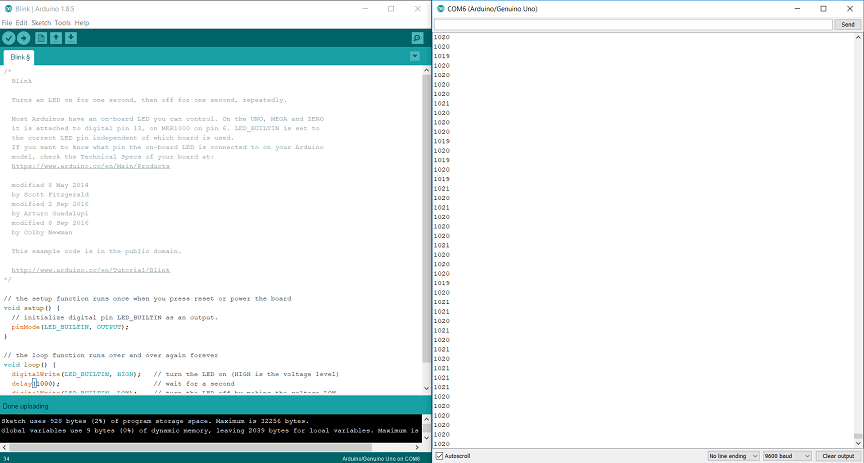
Serial monitor read
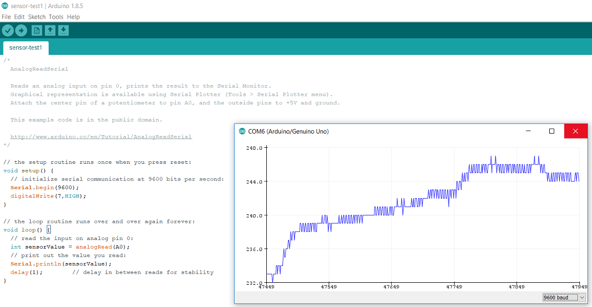
Testing Analog
Sensor #2
Merge the input and output into one circuit board for the final project goal
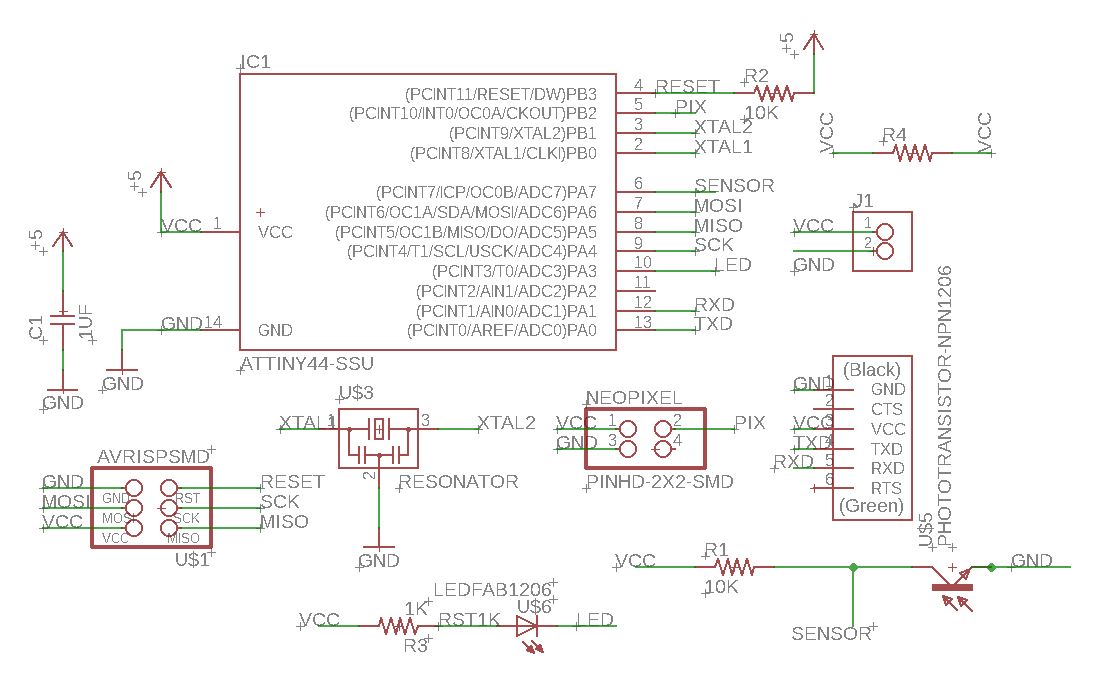
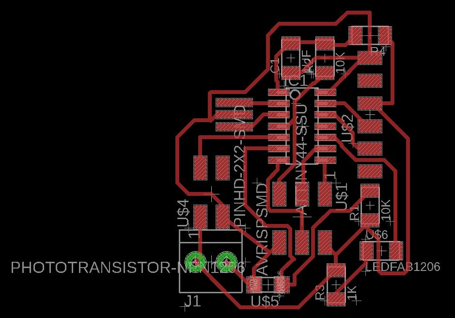
After making sure that the sensor works effectively, I moved to a full cut of my board which contains the visible components in the given schematic.
So the Input is phototransistor ir sensor and Output is neopixel.
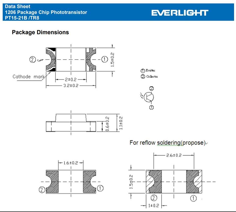
How datasheet helped:
This Datasheet helped me determine the correct pinout of the sensor.
It was better to prepare the pcb for the final project. I thought I would use a phototransistor ir sensor that senses objects passing from a certain distance with neopixel led strip of the coffee table "final project".
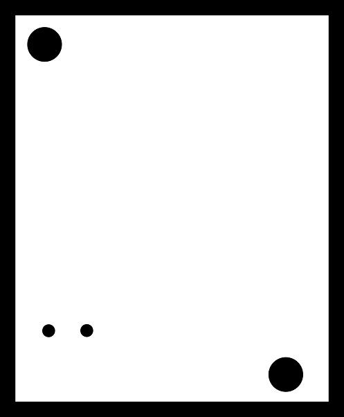
Here I learned how to make circle that will be used for mounting the screws using Corel Draw software and both circles will be using for screwing the board.
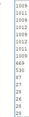
Testing the sensor readings
Sensor reading from serial monitor so the numbers above 1000 are the readings in the dark place and the numbers which shows in 20s up to hundreds are the reading of the sensor in bright light.
This is the Arduino code I used to read the sensor.
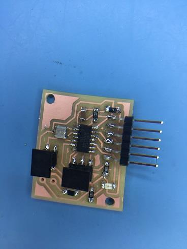
Using the board to test the sensor
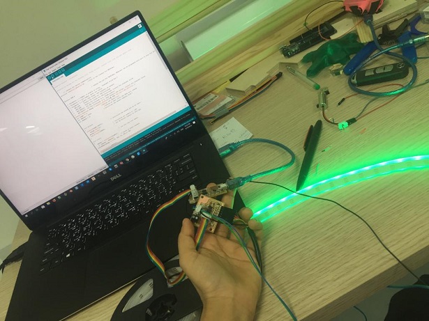
The video shows that the sensor interacts when the light is reduced or increased using the my board so when light is reduced, the color turns green, and when the light increases, the color turns red
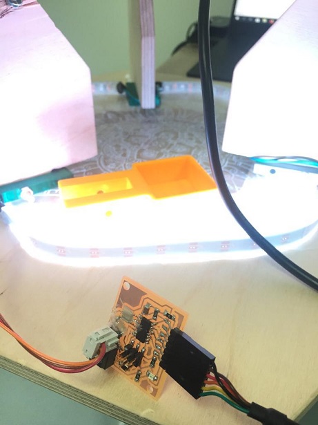
Here you can see the final outcome as I installed the board under the table and connected it to the light and you can see how the sensors respond to the light clearly and beautifully.