Week 12:
Output Devices
As I mentioned in the previous week 11 that I incorporated the input with output in one board. However, here I will focus my explanation on the output only. I would like to use the neopixel RGB led in the final project, as I try how the RGB led works and connect it to the sensor.
Steps of making my board:
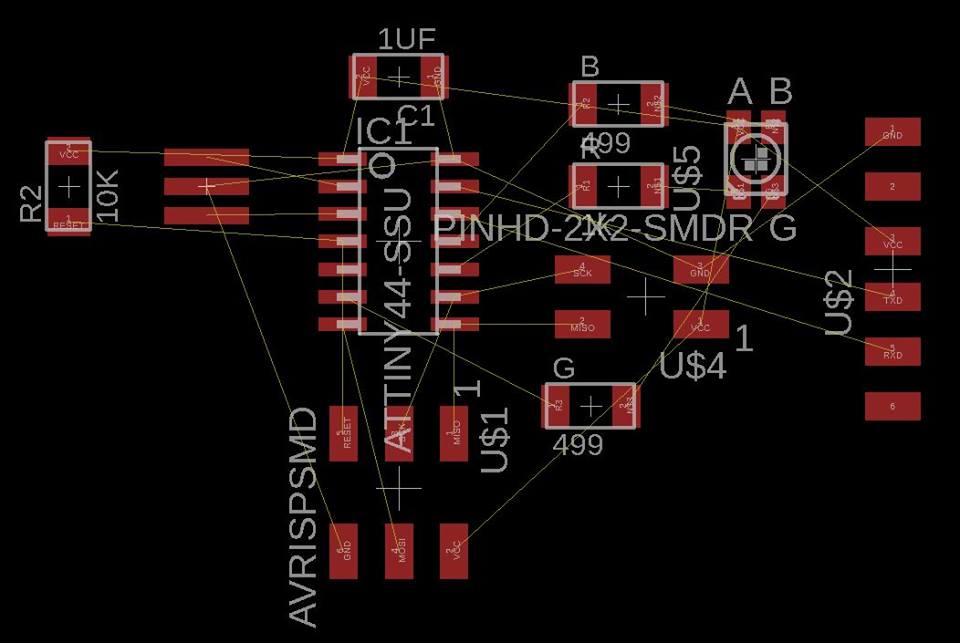
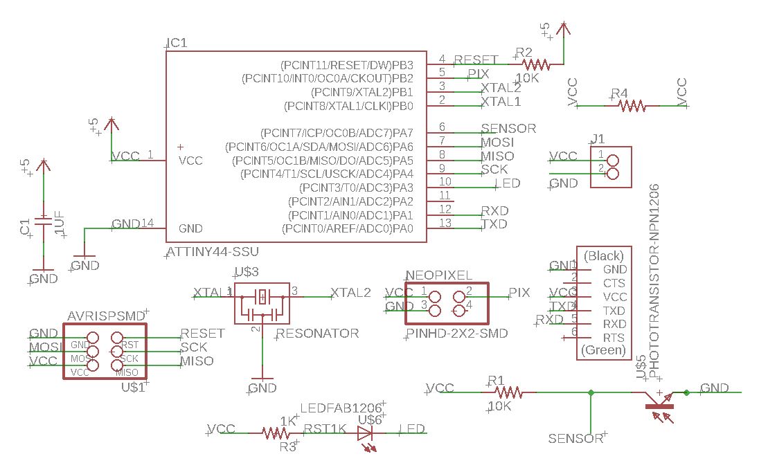
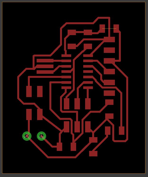
My plan is to make the input and output in one board, so this is the schematic of the board here:
This board's schematic includes the output the RGB for this weeks assignment.
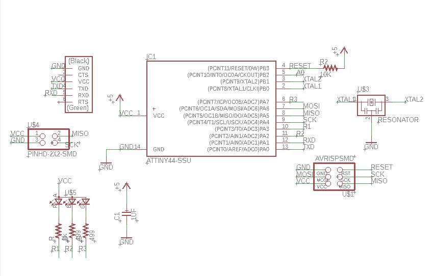
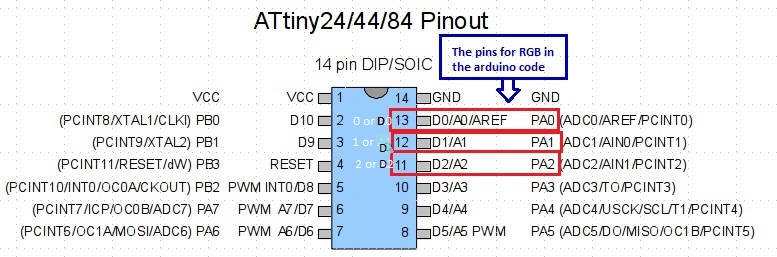
This is the pinout of the RGB led taken from this datasheet

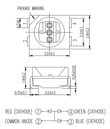
The RGB has 3 leds: Red, Green, Blue and they have a common anode. Hashim explained to me what common anode means and how it work. So you see in the image that the anode is (+) VCC and all RGB connected to the anode which means they are all conected to the VCC but from the other side they all connected to different pins which is (-) Ground, so you can turn them off separately.
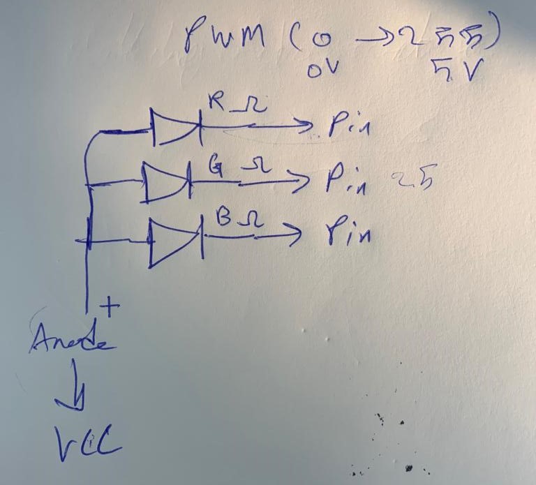
PWM (0= zero volt 255= 5 volt) and here we can change the numbers between 0-255 regarding to what color you want. So the RGB will work in reverse way so for example if we give the LED 5V it will turn off because then the LED will connected to the ++ in both sides.
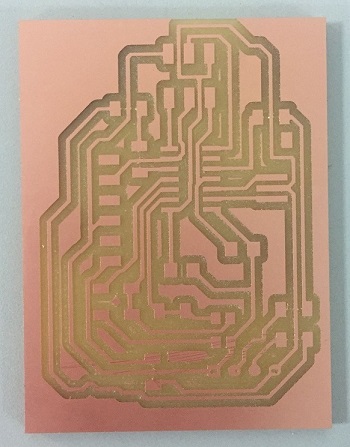
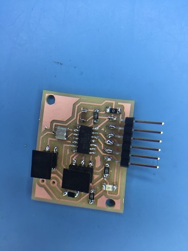
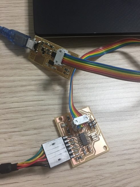
This is the first board
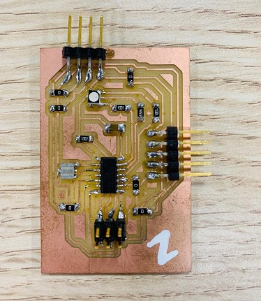
I learned a trick from Hashim and Salama it is easy and quick way to connect all traces and thats by using jumpers as a bridge over traces.
Here is the code which I modified from Salama code so I changed the color code and pins regarding to my board.
So in the RGB LED the red colour is connected to pin 1 or D1 in attiny44, green to pin 0 or D0 and blue to pin 2 or D2 and "D" here means digital.
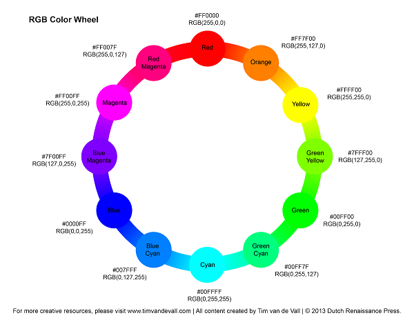
This chart or illustration helped me to figure out the number and its value as I began to choose colors by changing numbers and see if it has same color. for example (255, 0, 0) gives red color, (127, 255, 0) maroon color and etc...
The video shows the colors and shows the code used and you can also easily recognize it from the graphic as mentioned above.
Why I changed the board
I have two reasons for changing the board:
The assignment
I used final project board. Also I added the eagle file in the zip folder at the end of this page.
I was very careful checking the pinout for final project board and coding.
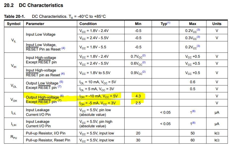
This is the table from the datasheet which shows how we calculate to have the value of resistor.
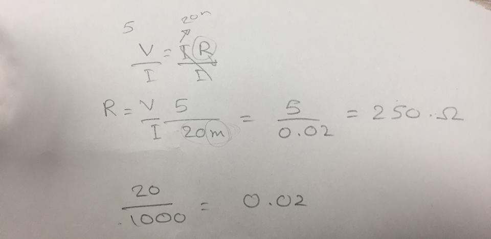
Here is an example we did in the section which Hashim gave us. So the equation of calculating the resistor in the image.
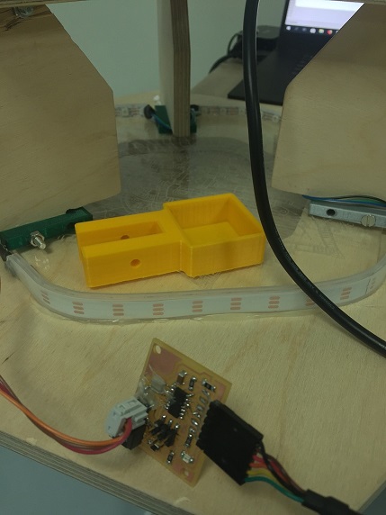
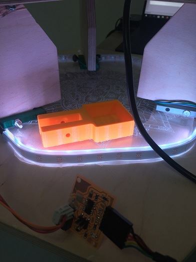
So soldering the strip of neopixel and testing by arduino then my board.
Testing neopixel strip with Arduino Uno
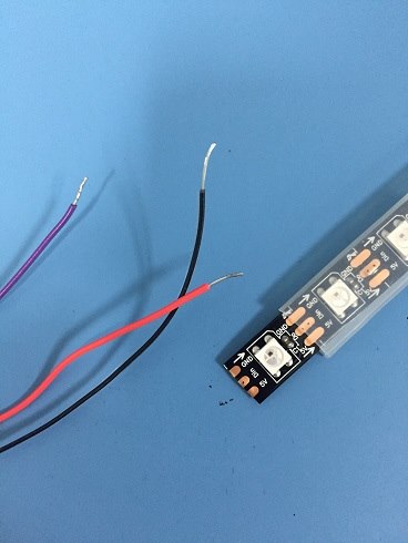
The test of the output "neopixel" from my board, please do visit project development page to see more , week 20
Arduino code
I used the baord I made for final project and here is the code which I modified it from Salama code so I changed the colors and sensor code regarding to my board.
Look at the steps for running the neopixel strip with images