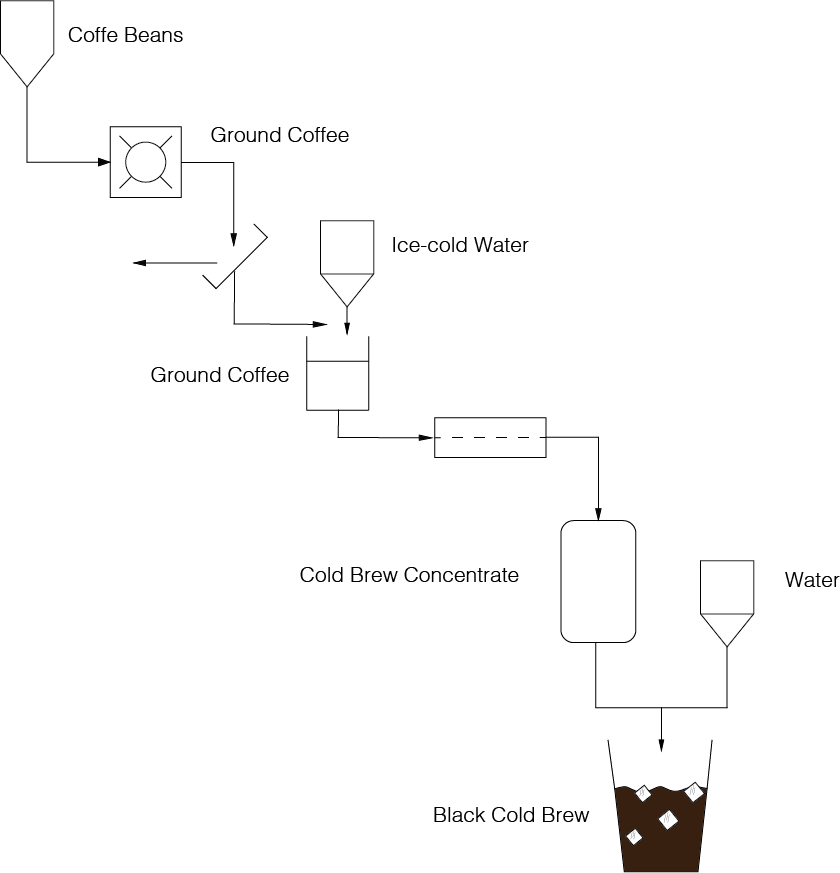
For my final project I want to create a "Fabable and Automated Cold Brew Coffee Machine". As my description says, I am a Coffee enthusiast. I find Cold Brew Coffee to be my favorite beverage during Lima's hot summer days. I was looking forward to enjoying Cold Brew this summer but local Starbucks' have stopped selling them, and I have no other way of purchasing the beverage. As I was researching ways of producing Cold Brew, I found out that the process was quite complex, and not so easy to recreate. I've found several machines which are either expensive, or don't allow for beverage customization. Also, this machines are not automated. The current process is as follows:
In order to schematize how complicated this process is, I drew an Industrial diagram of the process.
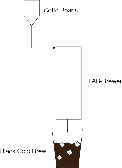
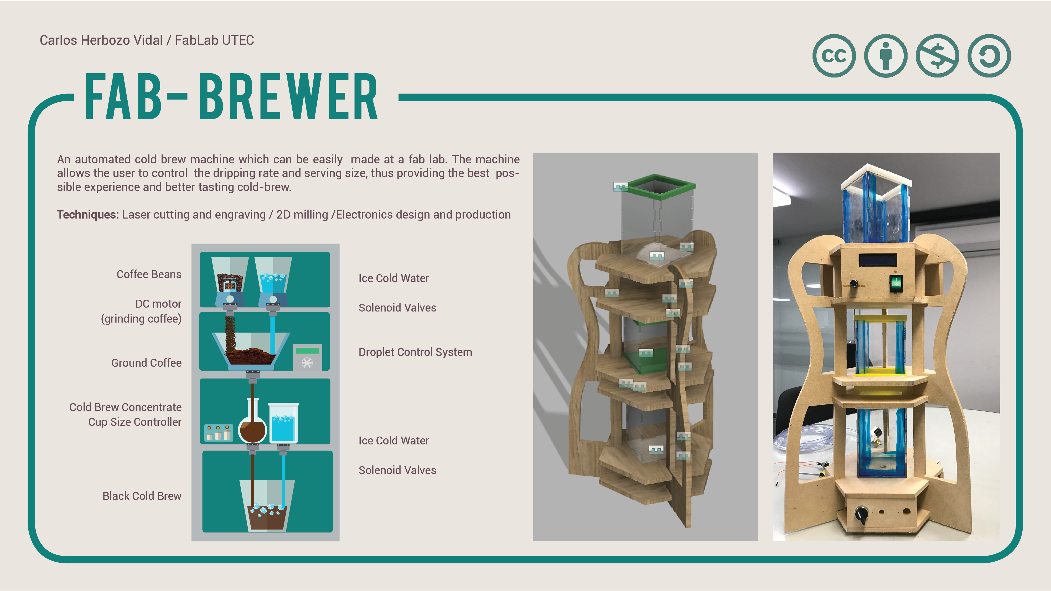
My idea is to create a single machine that can perform most of these procedures (except the roasting), so that I can recreate my favourite beverage whenever I want. I've decided to name my machine, the "FAB-Brewer".This is what I am proposing:
As part of our first assignmet, I had to sketch how my project would look, so I used Adobe Illustrator to generate a 2D general sketch of the machine:
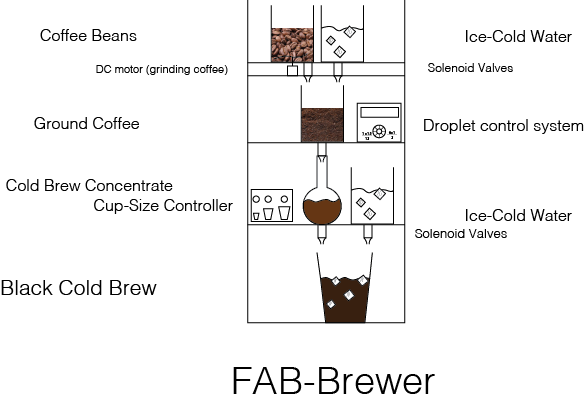
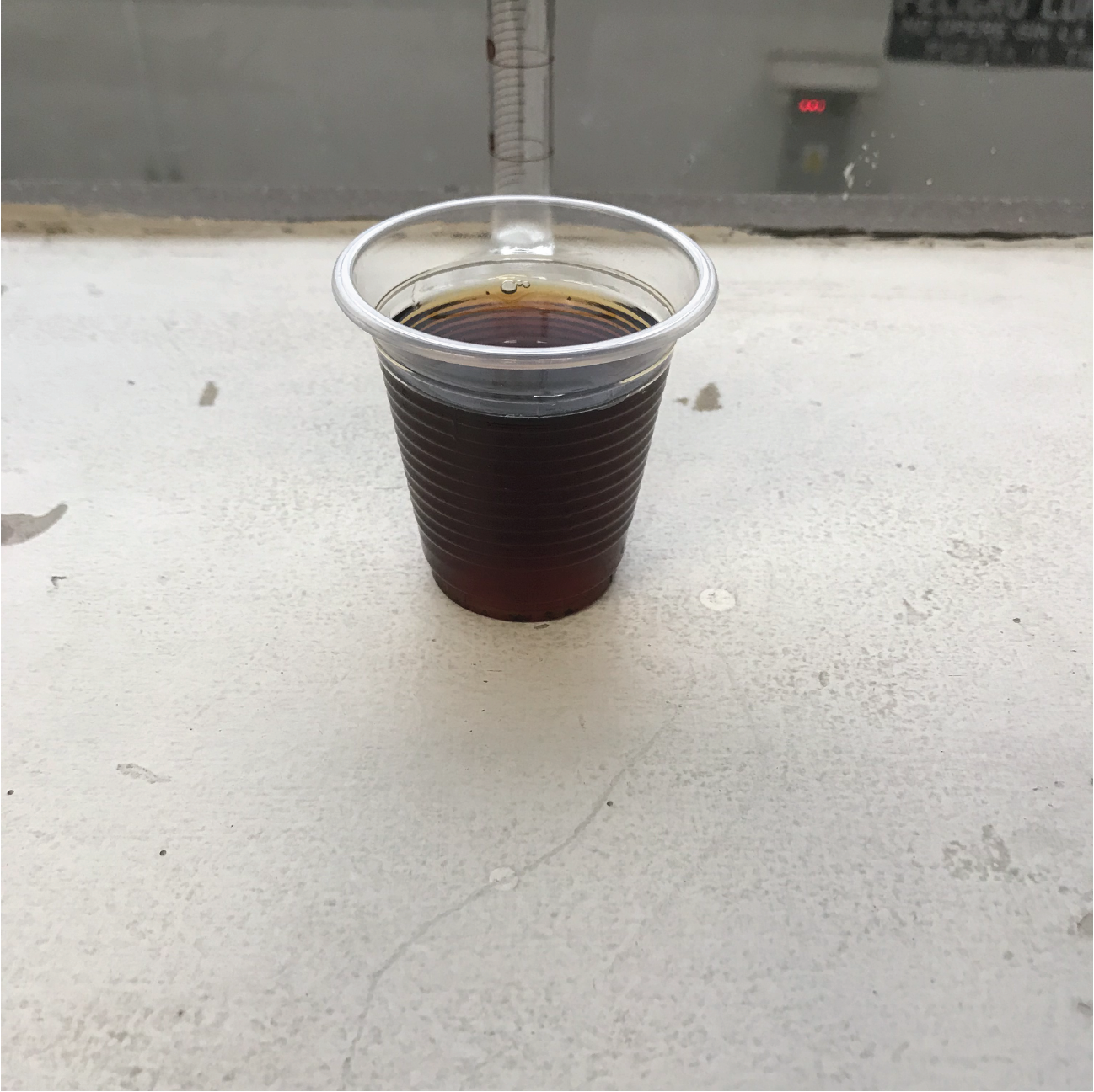
Here's what the machine will do: First, after the roasted coffe beans have been inserted in the container, a DC motor will start turning, activating the blades which will grind the coffee. The resulting particles will then be delivered to a second container where the essence will be extracted by a slow-dripping process. The speed of the slow-drip will be adjustable, so that different results can be obtained. A "faster" 2 hour slow-drip for a more bitter and less caffeinated coffee, and a slower 12 hour slow-drip for a stronger, less bitter cup of joe. Afterwards, through a coffee filter, the Cold Brew concentrate will be moved to another jar where it will be stored. Finally, the user can select a cup size, and the concentrate will be mixed with water, thus producing a delicious cup of "Black Cold-Brew".
This week I've worked on most of my final project. I've come near completion, and I'm currently working in the integration of every piece. In order to document the process properly, I've answered the following questions:
The deadline is Monday June 18th 2018. It is currently about a week and a half away.
I have already completed most of the tasks. I Laser cut the tanks, 2D milled my structure with a MultiCAM machine, 3D printed the grips, designed, soldered and tested the boards, and I've programmed the software. The only tasks I hav yet to complete is the integration of all of the pieces. At the end of the documentation there's a series of images which show the process.
Since I have already assembled the tower and tanks, and programmed the electronics, This week I'll focus on wiring and hiding said wires. This task should take about two hours or so, so all in all, I do have time to finish my project. I will integrate it this monday (June 11th) so that I can have the video and slide ready for my presentation.
So far most of my designs have worked. Both the laser cut press fit and the 2D milled press fit work perfectly. Thanks to what I learned from my 3D printers during week 6, I managed to print the grips with the right tolerance. The electronics were a little harder, because soldering is always a terror, but I've managed to make it work.
The only problem I've had is with my peristaltic pump. The electronic current it consumes varies with the speed of the pump. When my pump moves fast, the current is about 0.8 amperes. However, when it turns slowly, the current escalates to about 4.7 amperes. These amperage is unsafe for my PCB's, so I have to keep working in an interval where the amperage is between 0.5 and 1.3 amperes. This means that the SLOWEST of the slow drips, will still be rather fast. This is something on which I'd like to keep working in the near future, but for the project, I'll have to settle for a fast drip.
The main question I still have is whether or not the proportion of water and coffe I've considered is the appropiate one. Fortunately, in case there's a mistake, it's not like it's something that can naver be fixed. If I considered too much coffee, then I'll add water once the levels run low, If I considered too much water, I'll turn of the machine once the coffe has stopped brewing,
During the completion of this project, I've learned a lot about electronics and integration. What I've liked the most is that I've acquired the ability to succesfully integrate a project and make it work propperly in a small amount of time.
For my final project, I started designing the way it would all look like once completed. I used fusion 360, because it's the software that I've enjoyed the most all throughout the academy. This is a sketch for my water and coffe tanks:
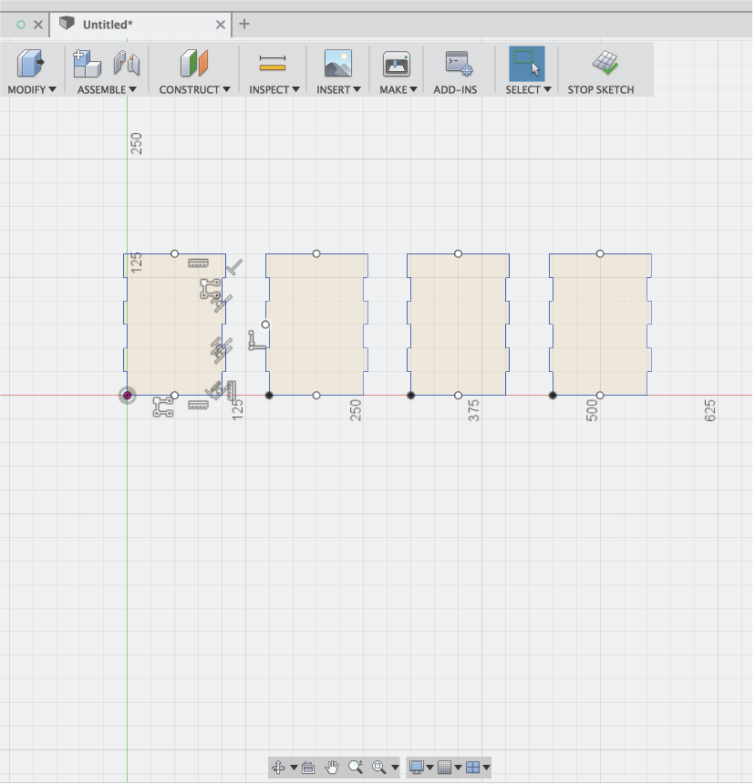
I have extruded the sketches just to show the assembly.
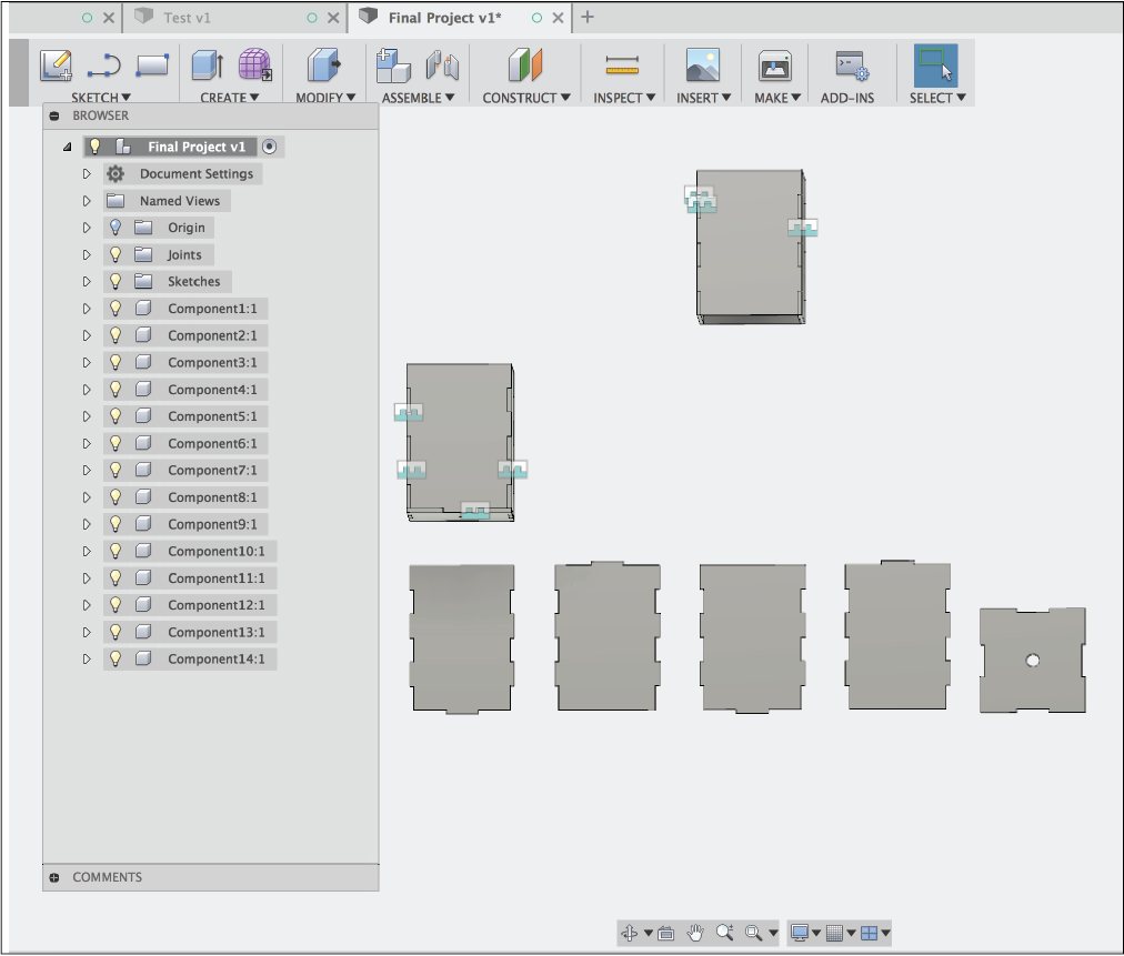
I started with the tanks and worked my way through the grips.
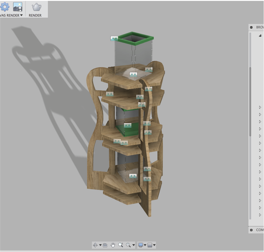
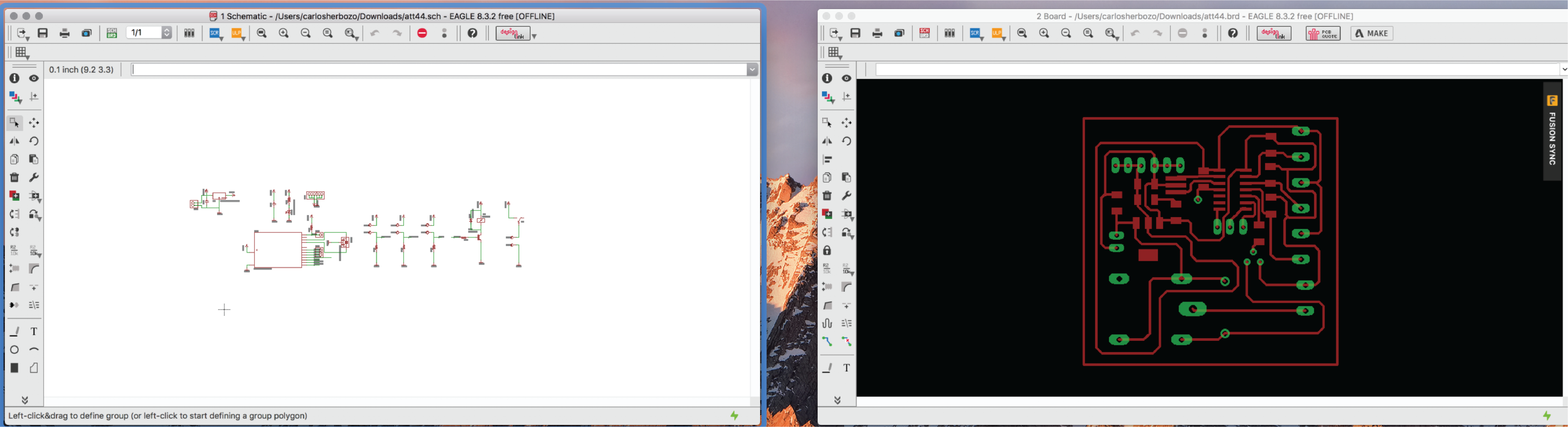
Finally, I designed the tower and assembled everything. Here's a renderized version of the project:
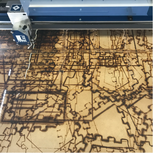
The first thing I did was Laser Cut the tanks. I used my epilog machine with the following parameters: Speed: 2%, Power 100% and frequency 100%. I had to hit play 3 times for the machine to properly cut the plexiglass. First I zeroed the machine...
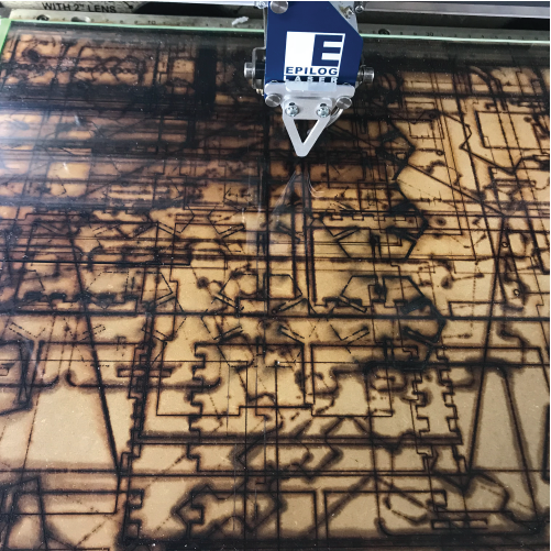
Then I cut:
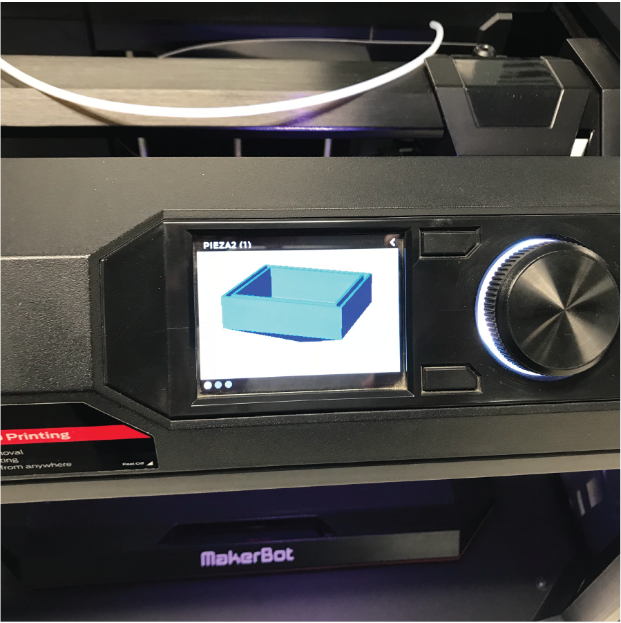
The next step was 3D printing the grips and the funnels I had designed in fusion 360. I gave an extra 0.25 mm as tolerance, because this is wgat we found during 3D printing week. I imported the files into the makerbot printing environment:
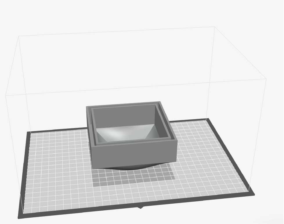
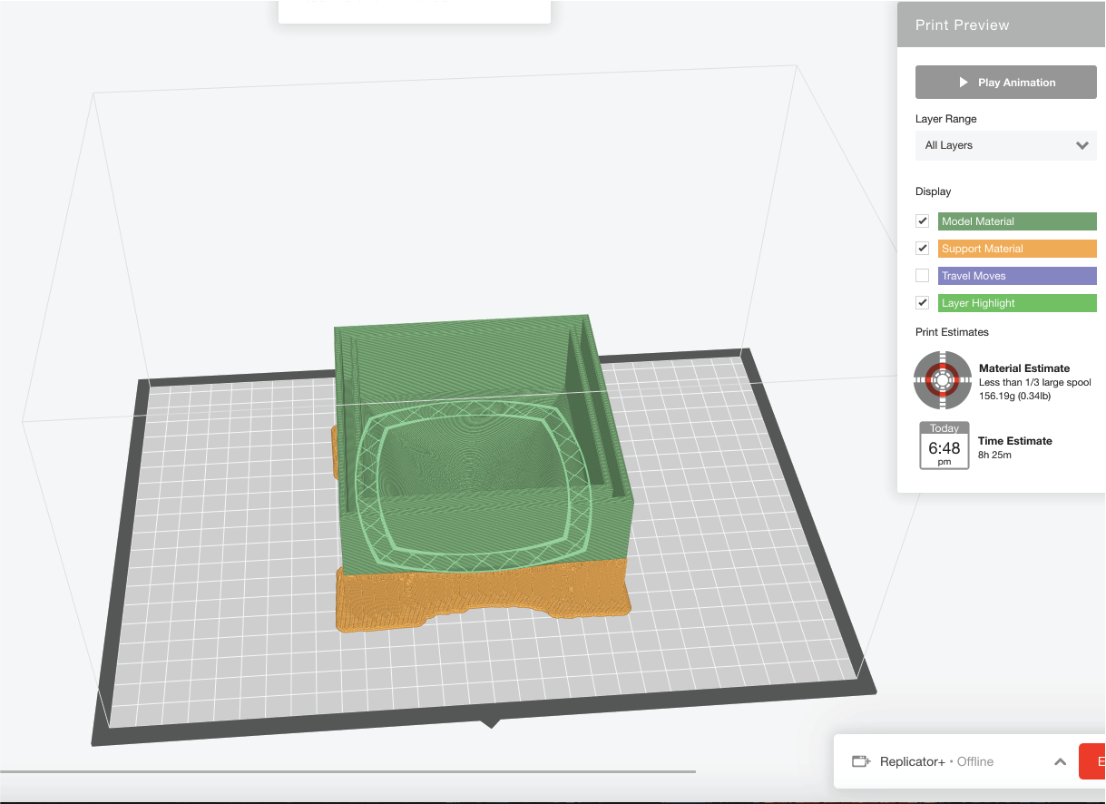
I worked with the following parameters: Extruder temp: 215 °C. Infill: 10%. Rafts: Yes. Raft to model spacing: 0.36. I did this for every piece and exported them. Here's the preview for the printing time:
And an image of the file before printing:
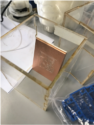
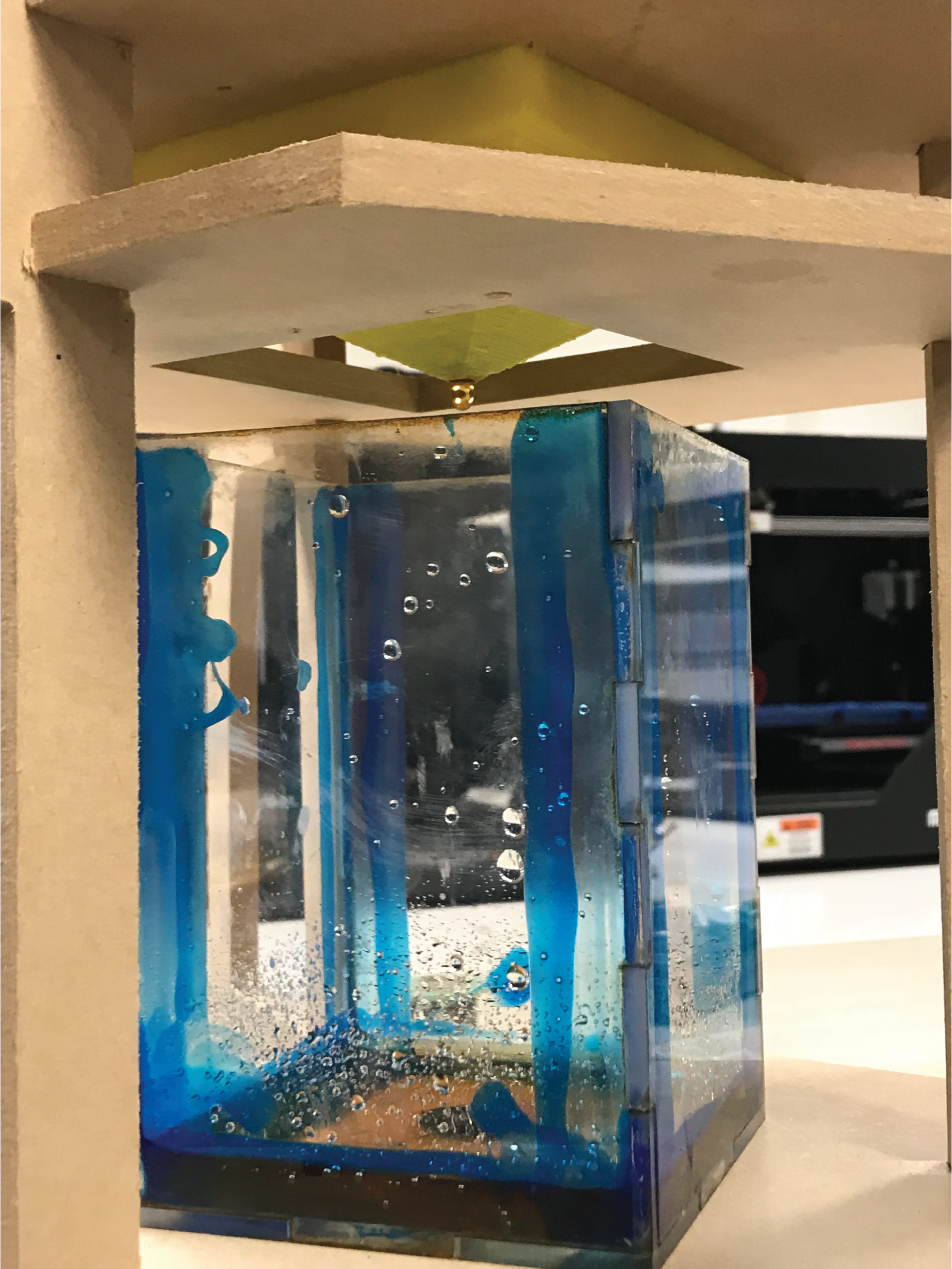
I then assembled the water tanks, using 4 mm-thick plexiglass. I realized that the water might leak through the prees fit joints, so I decided to secure it using fish tank silicone. Unfortunately, I only had blue silicone, and the effect it created is not what I intended. Still, it works against leaks so, I'm happy with the result.
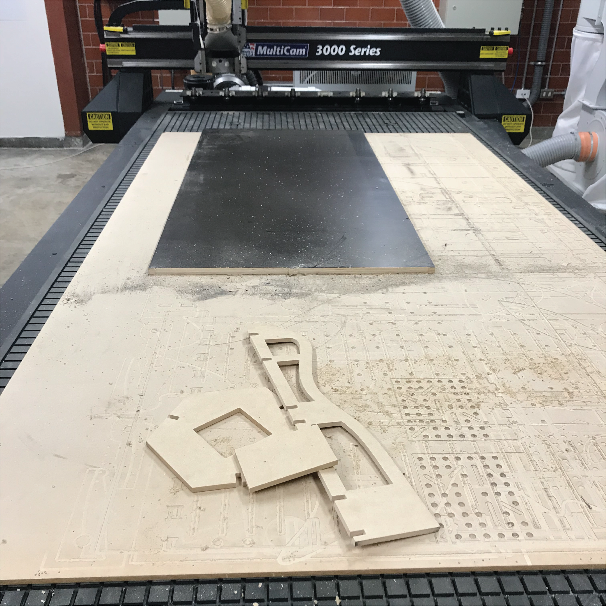
I proceeded to 2D milling the tower using a Multicam Machine. I worked with 9 mm -thick MDF, just as I did during "computer controlled machining". I assembled to check the joints and see how the machine would look like in the end. I used the enrouter software to do the CAM processing:
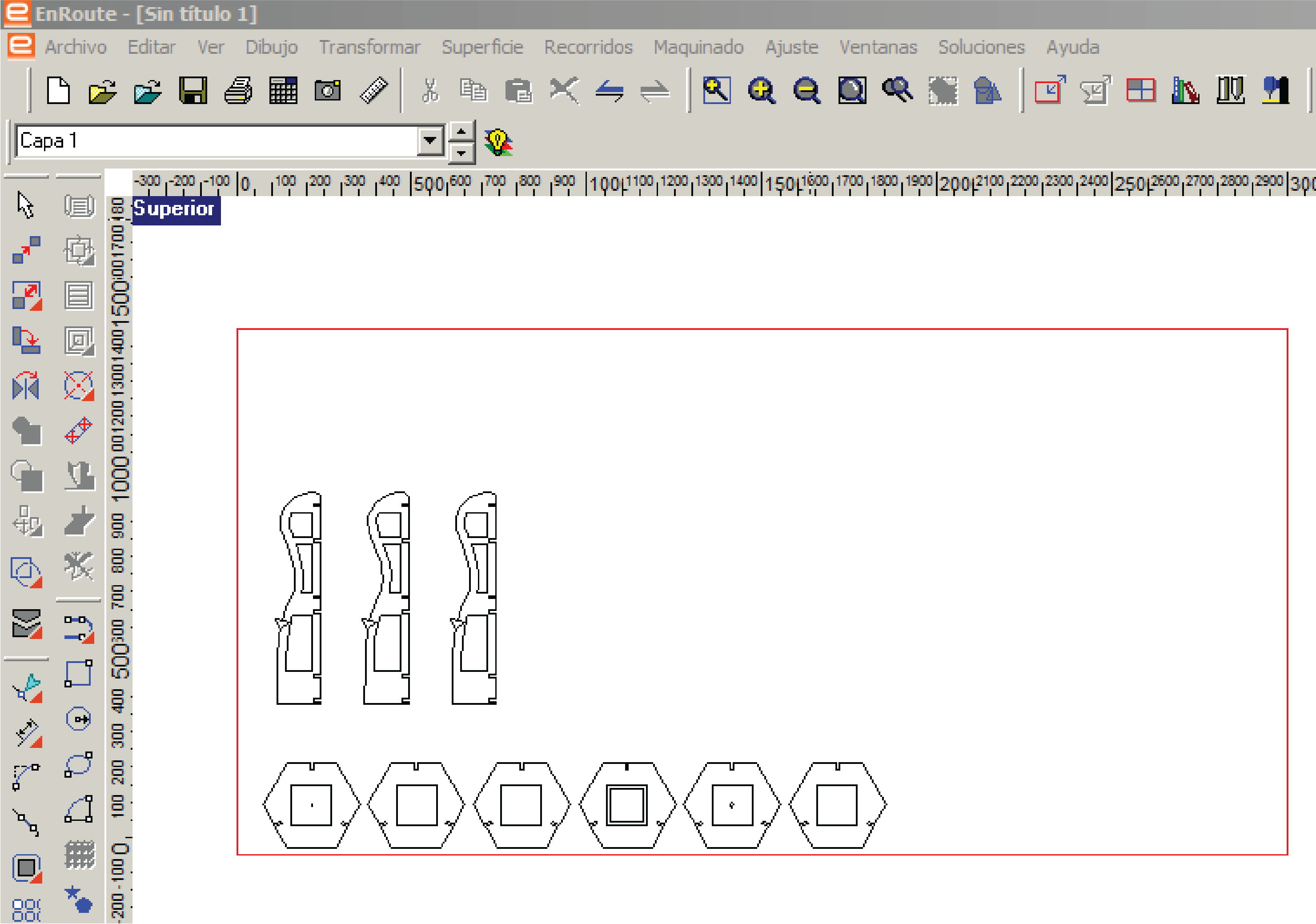
I cut 3 type of pieces, the vertical ones for stabilty, the hexagonal ones for each of the 6 levels and the rectangular ones to hide the electronics:
Here's what it looks like after assembling everything:
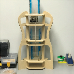
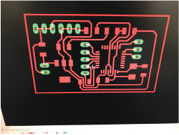
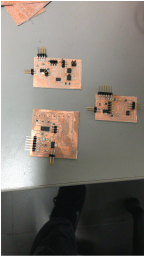
Once I had the designed figured out, I worked on the electronics. I started by designing my 3 boards:
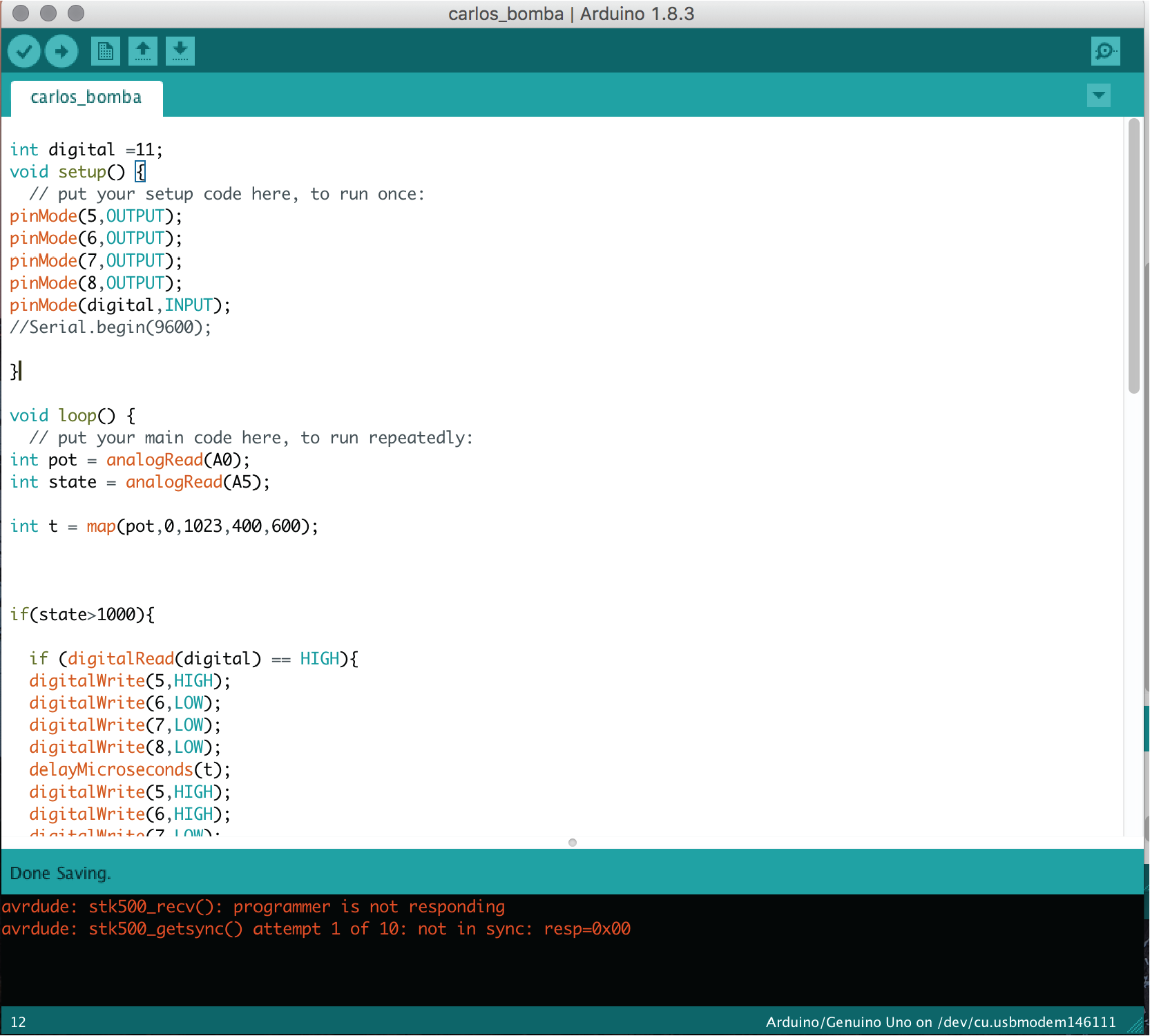
The first one is the one which controls the peristaltic pump. The board receives the information from a potentiometer, a switch and a DS18B20 temperature sensor. If the temperature is low enough while the switch is on, the pump will start working at a speed which corresponds to the data sent by the potentiometer.
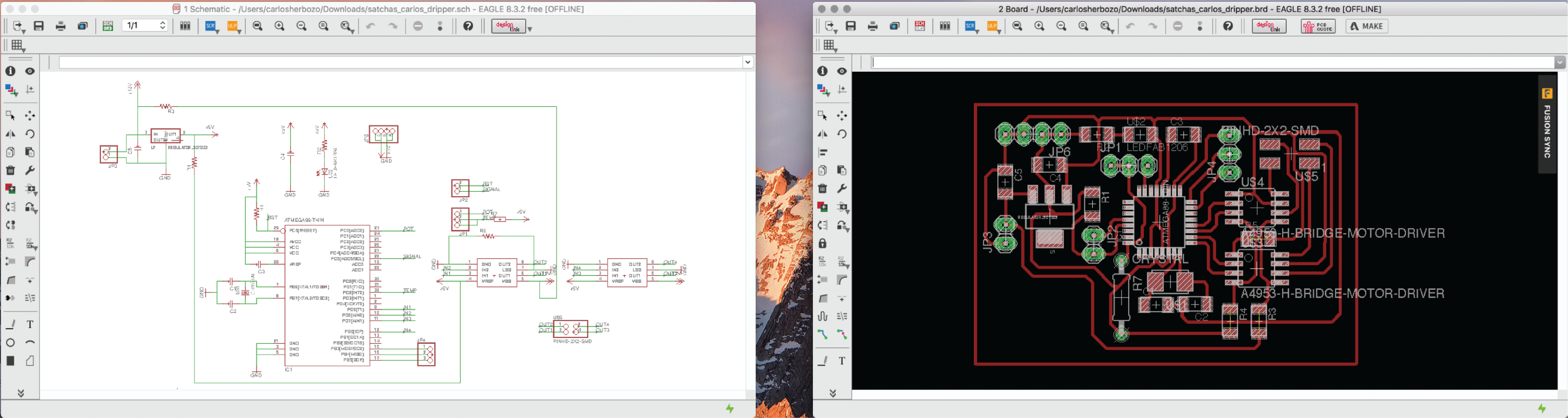
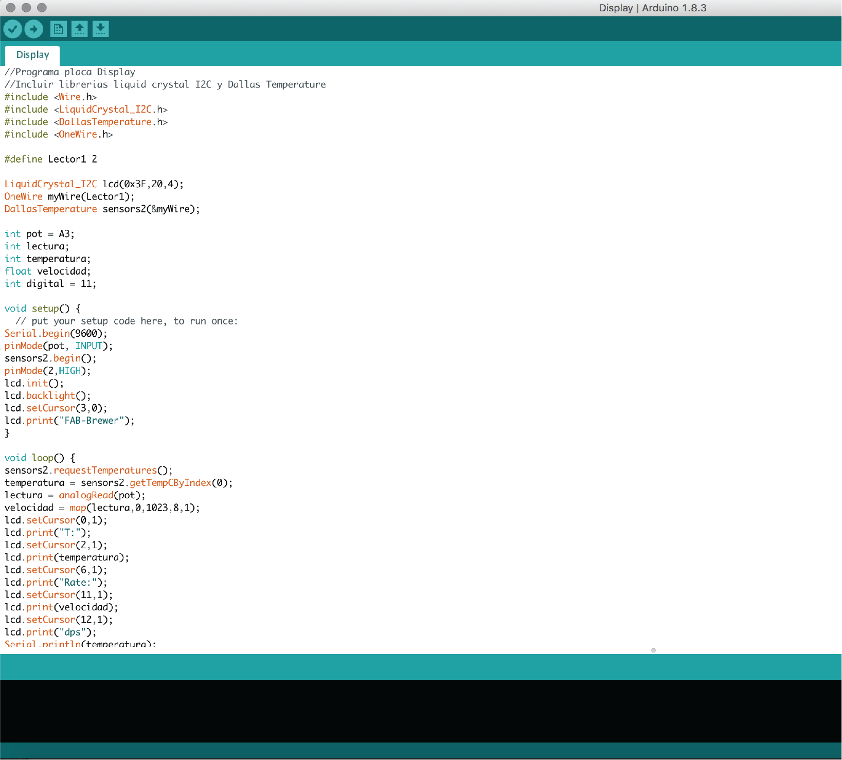
The second one is my "user interface" board. It receives the data from the temperature sensor and from the potentiometer and displays it on a 2x16 LCD screen.
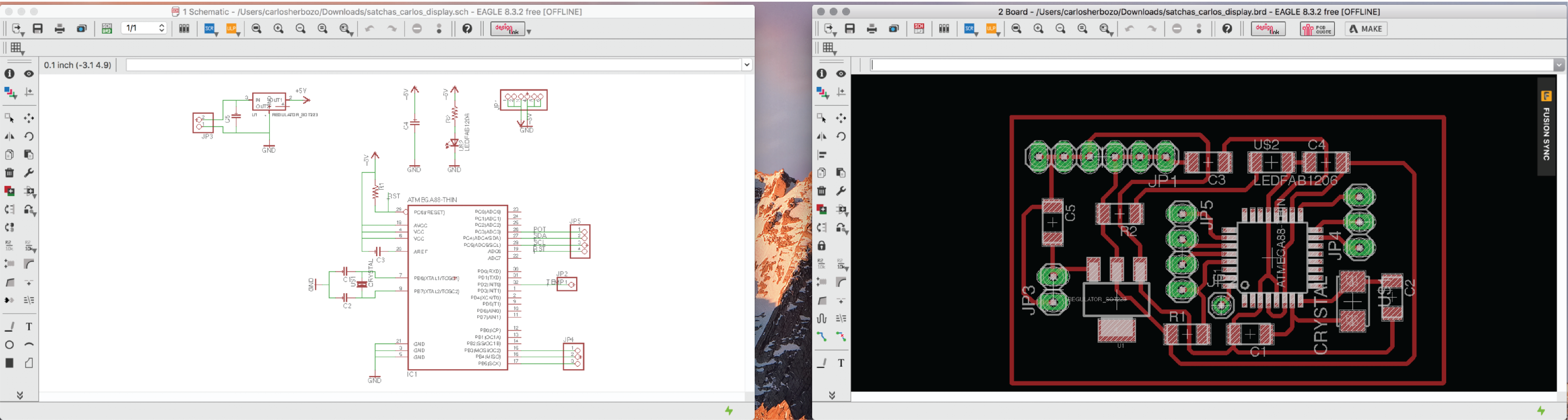
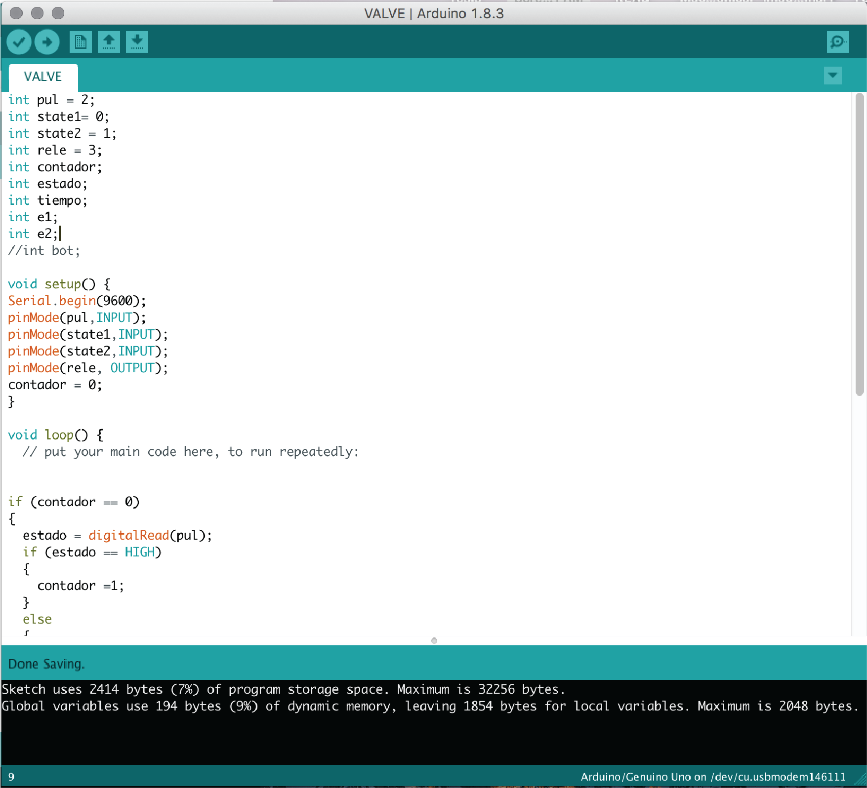
The last one is my Solenoid Valve board. It uses a relay to control the valve, and a switch and selector to indicate the serving size.
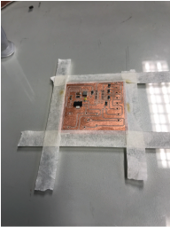
I then routed and milled the boards. Working with the ATMega 328 has always been tedious, so I had a rough time designing the boards. In the end though, I managed to get all 3 boards in time.
Once I had the boards, I started soldering. I started with the SMD components which were not the ATMega 328. I soldered my first board....
And the second one....
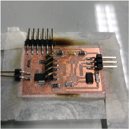
And the third one...
And then I had them all. I just needed to program my boards.
I used the arduino environment, because it is the IDE with which I'm more comfortable. I wrote three different codes, one for each board.
My first code works like this: If the signal given by the second board is "HIGH" than it means that the water temperature is appropiate for brewing. If it is, then once the switch is turned on, the peristaltic pump will start working. It works with an 8-step stepper motor, so I used almost the same program as in week 12, with a variable delay between each step. The delay is set by the potentiometer.
The second code works like this: The display is always on, and showing the water temperature and drip rate. The temperature is given by a DS18B20 water proof temperature sensor. If the temperature is low enough, the board sends a digital "HIGH" signal to the first board.
The last code runs separately from the other 2. The Attiny 44 receives information from a selector and a push button. The selector has 3 positions, which in turn control the cup serving size: Small, Medium, Large. When the push button is pressed, the processor chooses a size accordingly and turns on a relay which activates a solenoid valve, and serves coffee. After a designated time, given by the selctor's position, the relay is turned off.
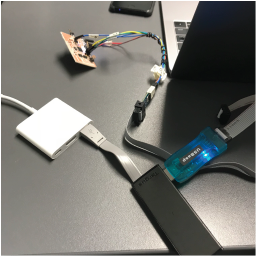
I used a USBASP to program all of my boards and burn the bootloader.
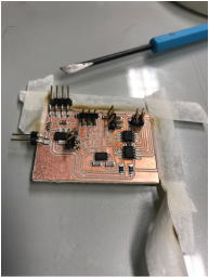
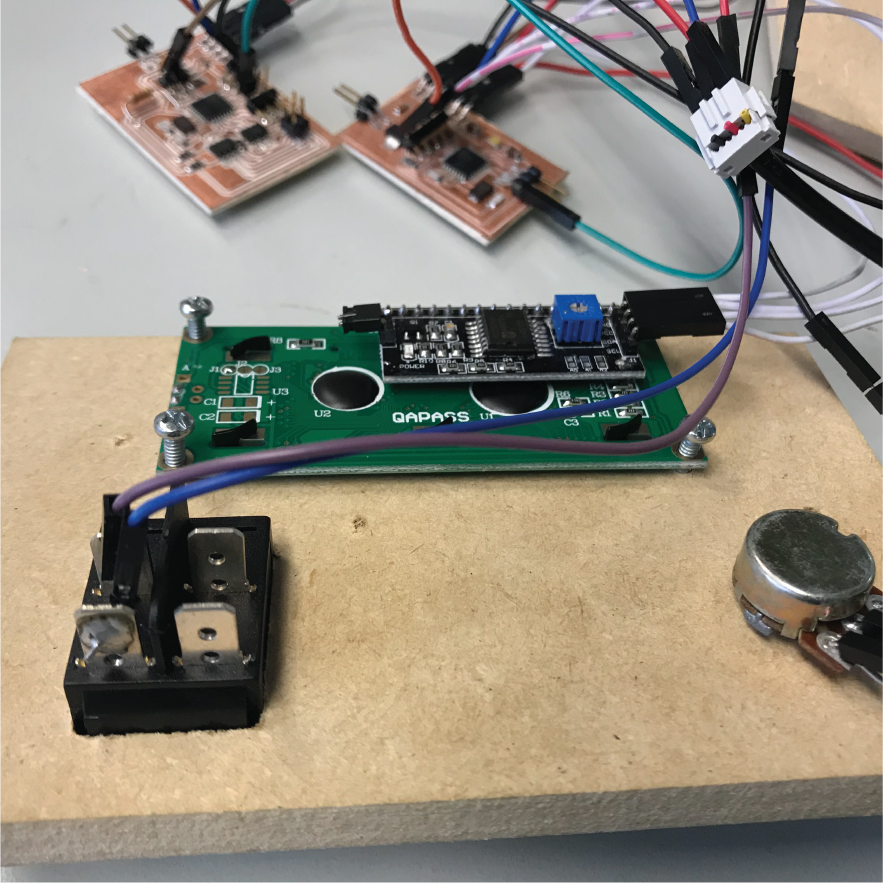
Then I started connecting the boards to the components, first with the user interface:
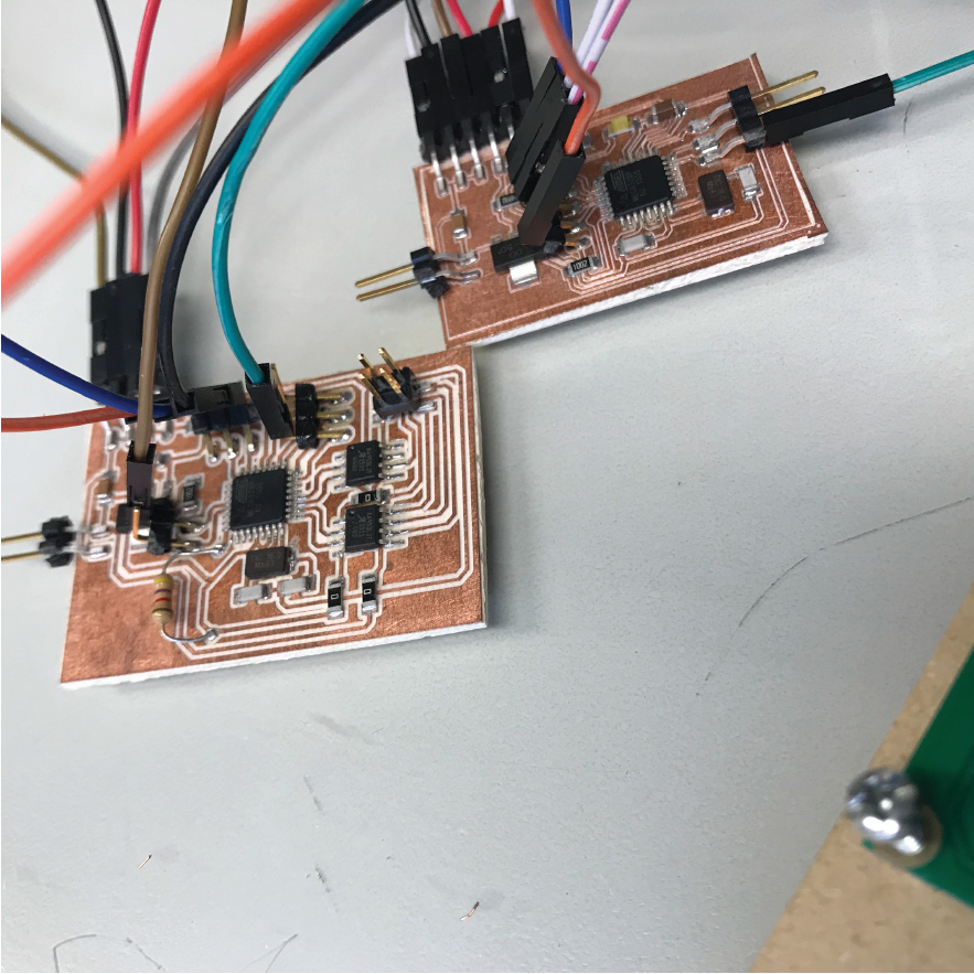
Then with each other:
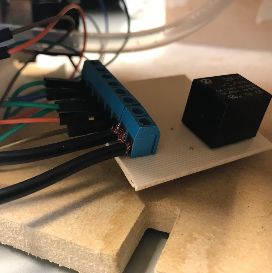
Finally I integrated the relay board:
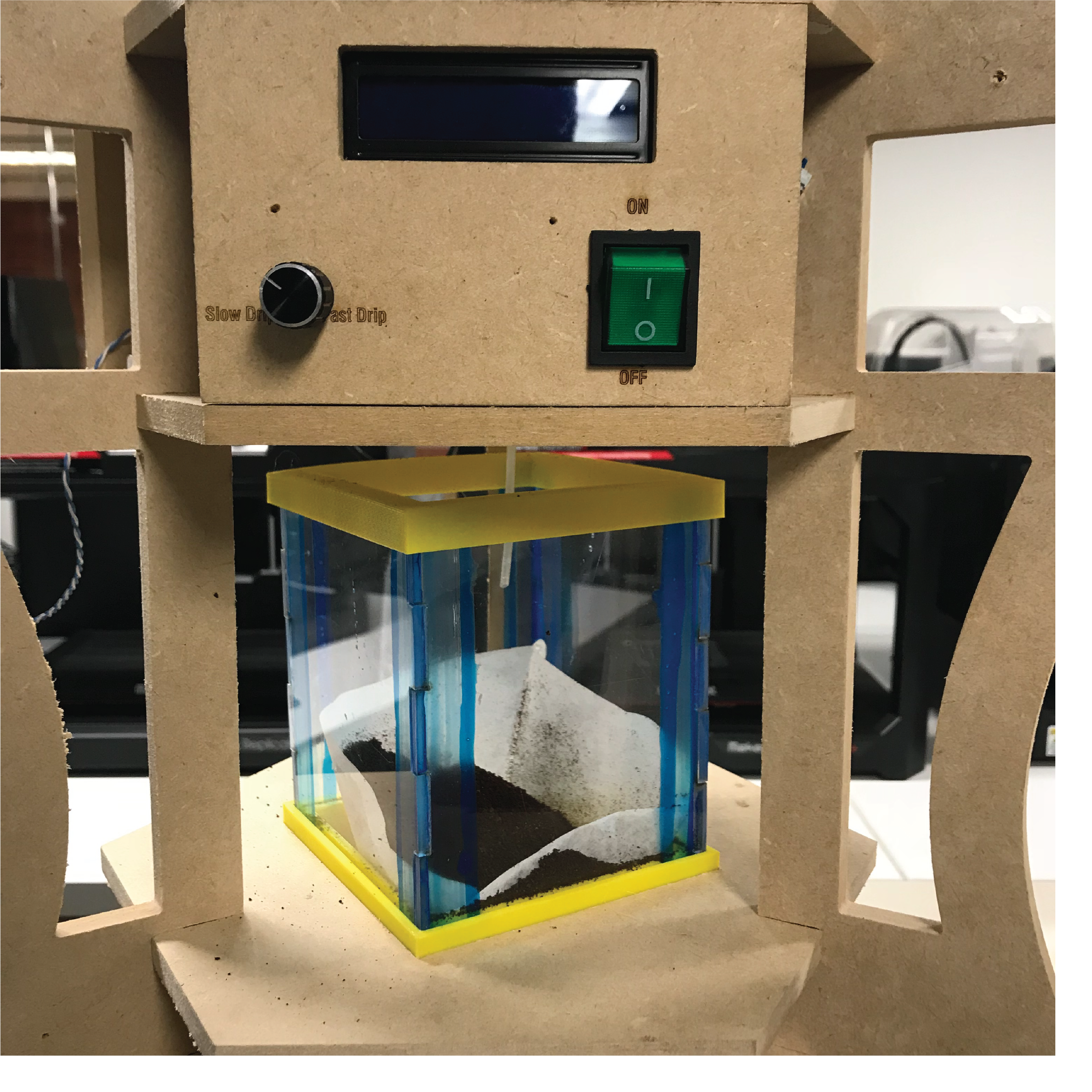
Finally, I decided to work on the user interface. The machine has two different interfaces. One for the dripper control, and one for the serving size control. I designed them with fusion 360 and milled them with the MultiCAM. These are the results:
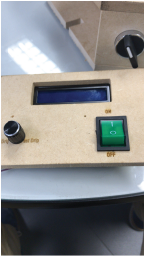
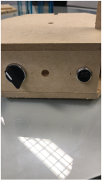
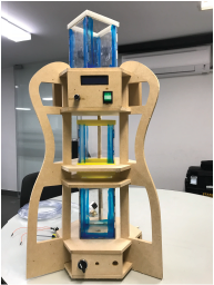
Once it was all cut, milled, and programmed, I integrated it all. and here's the result!!!! The FAB-BREWER.
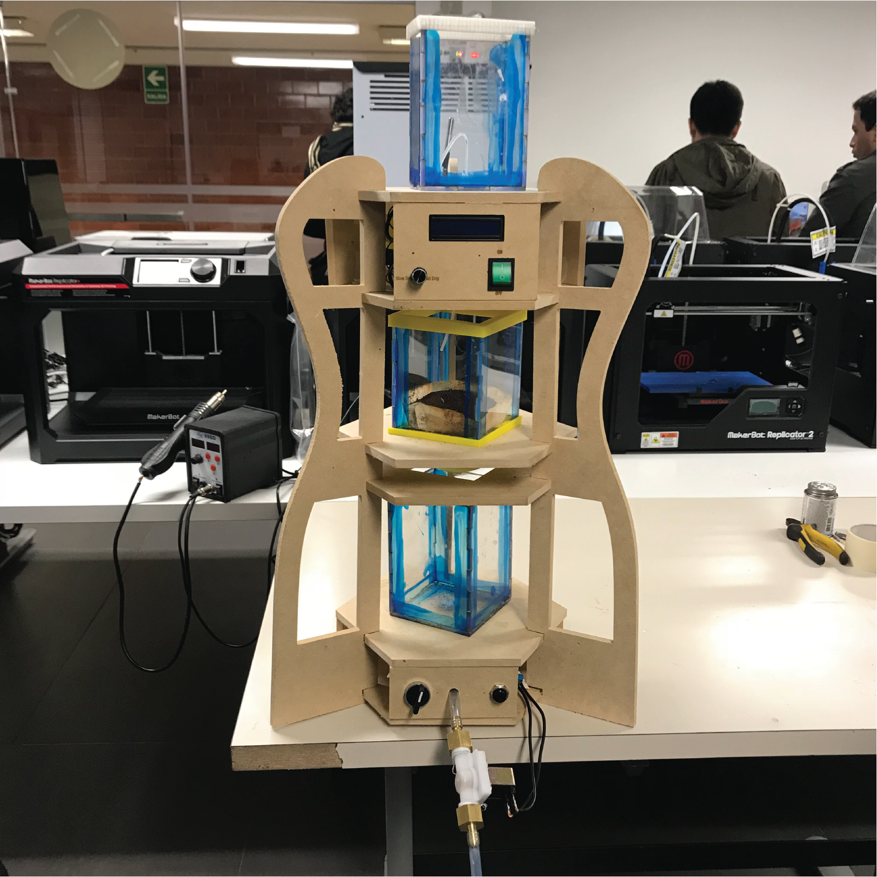
But how is it all powered? I used a 12 volts and 5 amperes external battery/supplier. This supplies all 3 boards with 12 volts, and, since they all have a regulator, transform it to 5 volts. These 12 volts are also supplied to the stepper motor and solenoid valve.
You can find my slide here And my video here
And here are all of my files: