Aim:
To learn to design in 2D and 3D modeling softwares
For this assignment I decided to draw and analyse different parts of my project, while studying the softwares parallely. So for this i initally divided the parts of my project into groups and decided what is to be designed and simulated in which software.
Task 1:
To explore any of the raster softwares
To start with we have a question..
What are raster tools?
The tools which work on definite amount of pixels and modify or rearrange them in a specific order are termed as raster tools Generally what happens in a raster is when you zoom into the details, the pixels get scattered out and then you are able to see the dispersion of component colours.
Softwares used
Corel Photo paint
This is one of a premetive kind of software which can be used for basic level masking and editing
it was actually developed to support Coreldraw which is one of the softwares used for graphic designing,
hence photopaint is just a supportive attachment, yet works quite well on premetive level
The basics of which I had spotted here
While exploring,
I decided to edit one of my photos which I wished to use for my portfolio
It has all basic features necessary for a raster to have
,
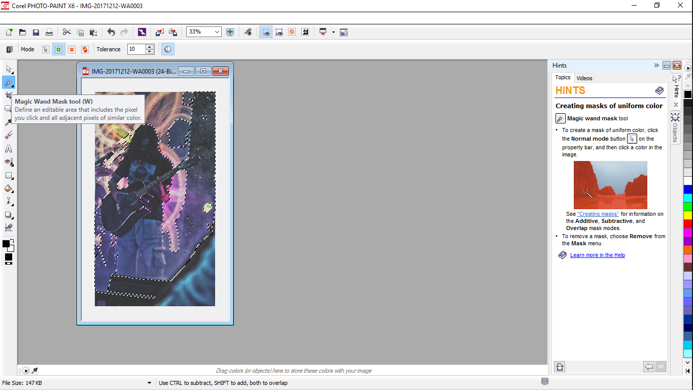
For my task I needed to cut myself out of the background , for
which I used the masking tool.
Initially, being a lazy guy I went for magic mask which auto selects your image upto a certain extent(as I considered),
but it turned out that it just works according to specific spectrum of colours. Hence this was something I had got
Later I tried to remove the red I effect inorder to re apply the magic mask(in hope to work), but it didn't.
Hence I decided to stick to the traditional masking
For which I faced following problems inividually:-
- magnetic mask-works considering the border lines again referring a colour spectrum
- free line mask- looses it's positions when u zoom in or out.
- lasso- works fine than above ones but it actually becomes difficult to relocate it's start point in order to complete the mask
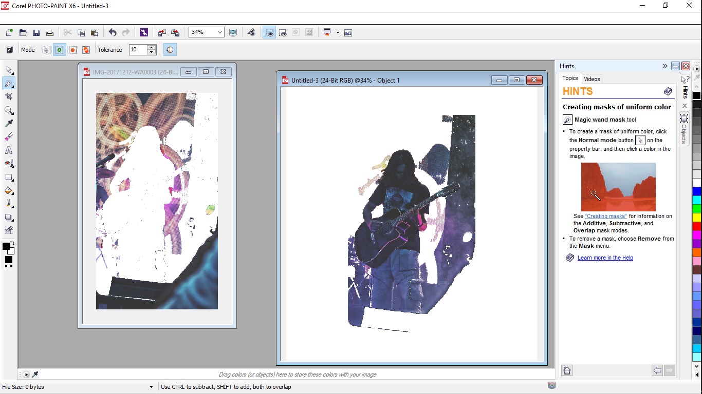
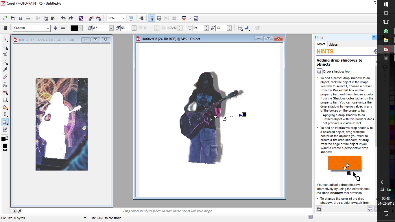
Hence finally I used the lasso for premetive selections and the brush mask to finish it and got the following results
Previous Experiences(comparing other softwares)
Also for comaprison i kept my previous experiences of working with the tool for rendering of all the images of my website, including this one..

Hence to compare and conclude i'll say;
Photoshop turns out to be powerful software when compared but is equally difficult to learn all the features
which help better rendering when mastered
And photopaint is a lower end software which actually can be used if
heavy rendering is not required.
Task 2:
To explore any of the vector softwares
For the vector softwares I decided to learn corel draw, for that I decided to draw the conceptual sketch of my final
project, since the first hand drawn sketch was a bit little shabby and the graphical imaged portrayed my concept even more beautifully.
Corel draw for that matter is quite an efficient software that I found, after using inkscape, paint etc
Corel has rather a good user interface on the contrary since it is a dediated application software there are a lot of commands
that run behind the screen and a lot of commands to make the job work on the screen.
All of the work actually was very smooth except for a few problems as listed below, because as said before the corel is a
dedicated application software.
-
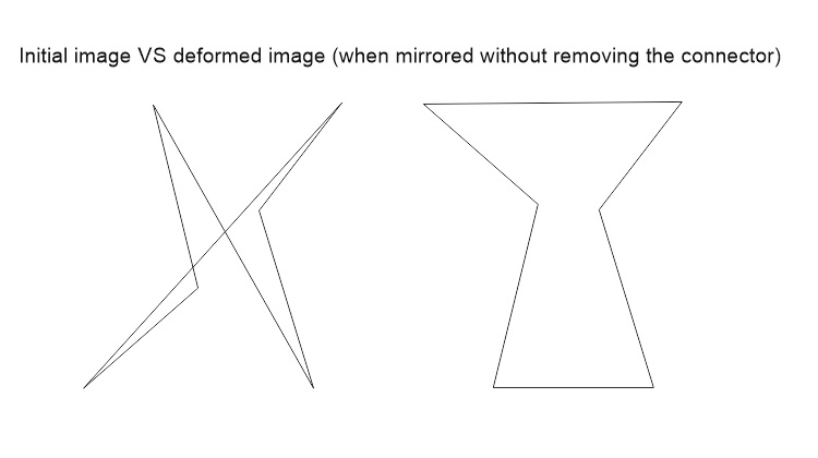
The first problem I faced was with the term called (connectors)
{i.e if you draw a line on a blank page it, by defaults gets anchored to the page and you actually go on sketching since there is no specific indication for that, untill you move the figure} Similar happened with me i drew my entire sketch and then when i decided to move it, it got deformed and looked something like this.
Solution:
Later after a few tutorials and some trouble shooting, the case is you actually have to break the connector apart by right clicking on the line and applying the command or simply selecting the line and pressing ctrl+k
{Note: This has to be done for every drawn line} Then what i faced was colouring the hoppers
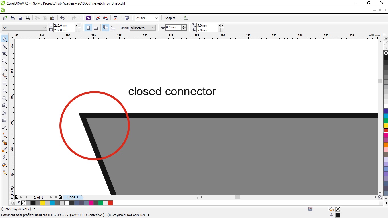
At first i had drawn the hoppers(Trapezium), from free lines. But some how I was not able to get a colour into it,
After trouble shooting, I came to a conclusion that it was because the shape was opened somewhere.
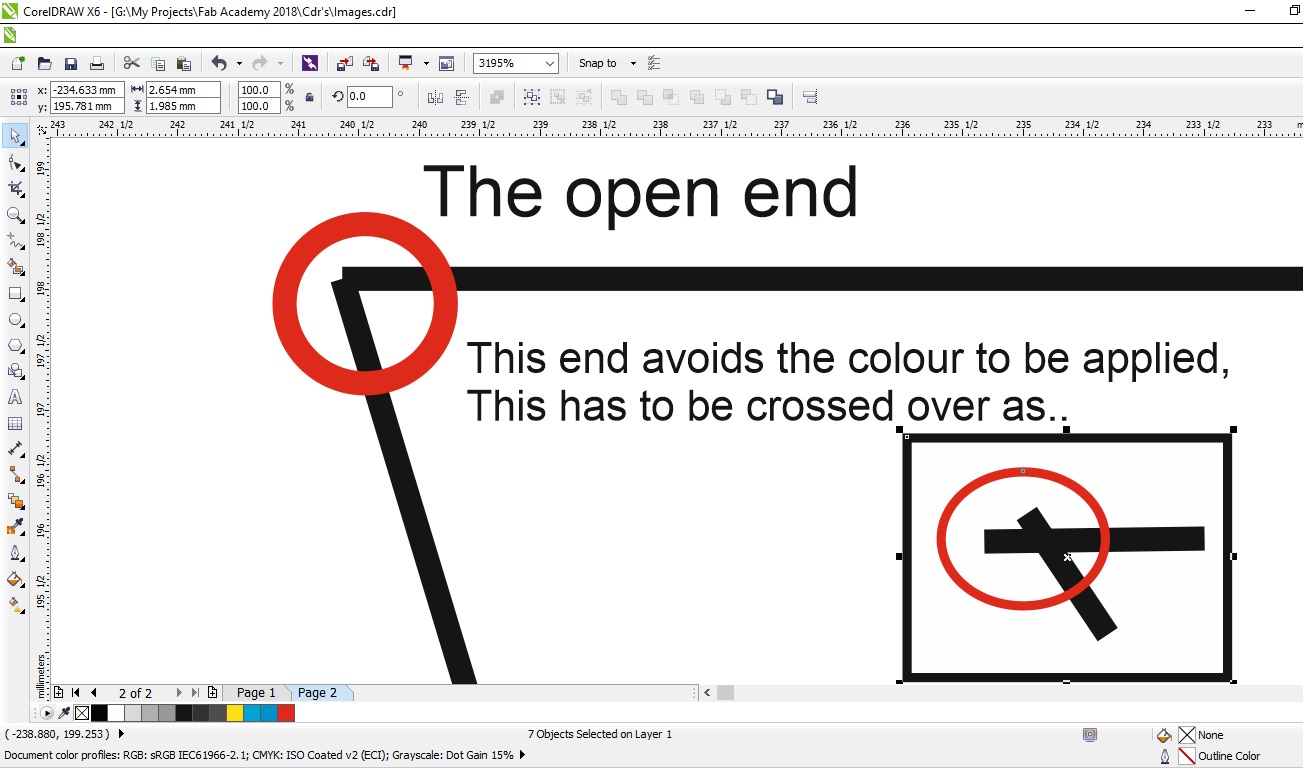
Solution:
So what i did was to cross the lines over each other, and achive the shape of that particular size inside the crossing lines
And then when you add colour, it appears inside and then the next logical task is to delete the crossed frame, to genrate a fresh new shape.
Task 3:
3D modeling
For this task I had decided to sketch the entire assembly of my final project using various softwares in the format of different
parts, and then conclude one to be the best to make the entire assembly into
The softwares I chose for this were:
- CATIA
- FUSION 360
- SOLIDWORKS
In general for these softwares there were no problems as such but I dealt with few experiences as a beginner which are enlisted below:-
-
Solid Works
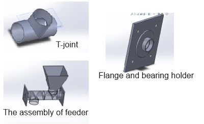
Solidworks in comparison had a very user firendly interface to offer to a beginner like me, where each of the command is explained before you click along with the integral features of it For this assignment i decided to learn to draw a screw feeder, construct the assembly right above it this was a complex task for the feeder to design initially i constructed to t-joint, beering holder and the hopper using basic commands of extrude, loft, shelling, etc, turorials of which I had found here...
There are two commands i would like to explain and i myself was facinated to use them
- One was the tool library which i used to insert the bearing , following are the steps used to go through it
a.First select a new part page, and go to the tools section, for the wizard to open as shown below
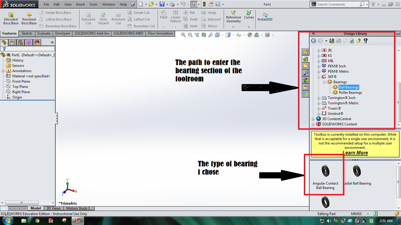
b.Select the bearing type, which is basically a standard format or standard orientation The bearing type i needed were 6000zz (the double z stand for covers on both sides)
c. Once selected insert the bearing and save it as a part, {note these tools are standard size son there can be no design modifications , if done may disrupt the orrientation}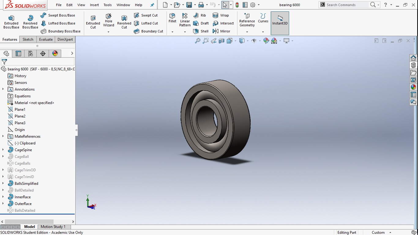
-
2. Development of a screw feeder
unlike in fusion that has a direct tool that can cut threads, solid works has a tedious process that is explained below
1. First you need to draw a base of the feeder( in my case a rod)
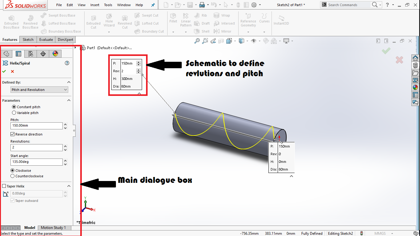
2. Then we have to draw a helix in which we define followin,
a.pitch of the thread
b.length of the thread
c.origin
3. Then u have to draw a figure or shape that will represent the feeder( in my case a rectangle defined the height of the feeder, along with the thickness of the thread
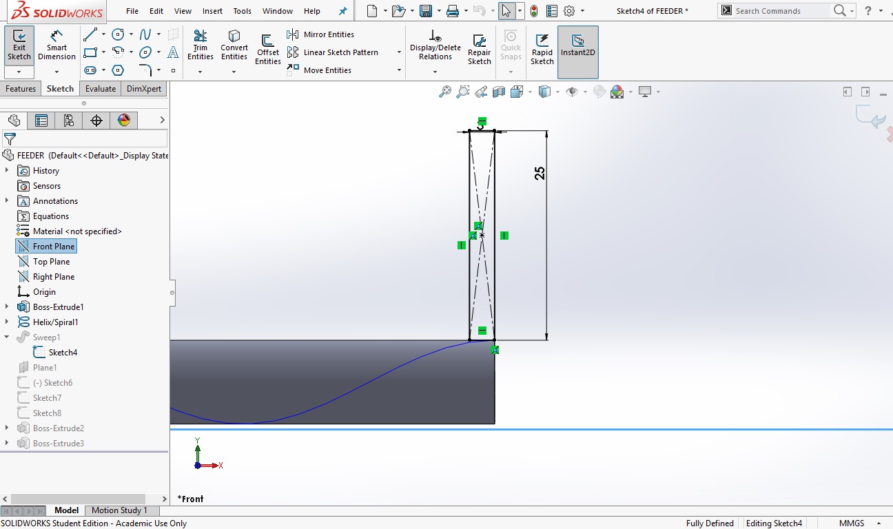
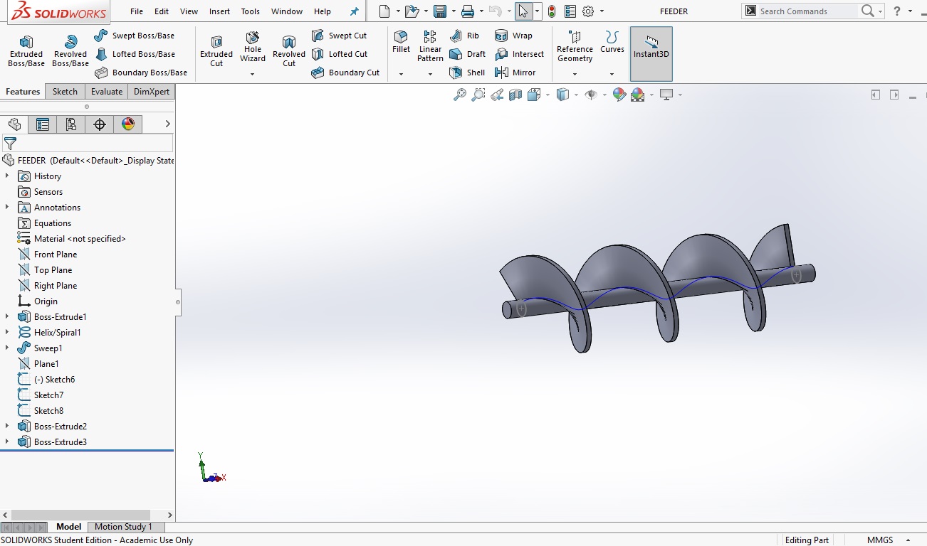
4. This is the major step where most of the times i fumbeled, we have to select the operation of swept bose which by mistake i had tried to make swept cut, which would naturally not work and hence in this way i was able to learn and develop the feeder and later i assembeled all the parts to make the figure look something like this.
- One was the tool library which i used to insert the bearing , following are the steps used to go through it
-
Fusion 360
This software is one powerfull software developed by auto desk it has a well defined and an easy graphical interface, and all the components can be accessed easily on the click of few buttons.
Also the best part of this software is it has cloud storage and computing hence considering all of this, fusion turns out to be once powerful software.
For the task of this software i decided to design a solid dish which i will include in my design as the final container.
Following data guides through the steps to build the dish
step 1..
If new to anysoftware of autodesk, you have to sign in to make your registry over the cloud, so i started as the same
step2..
This step was to develop the actual sketch the dish So for this i went into sketching where i first drew a random shape that woud look like a dish, and gave it dimentional, and geometrical constraints, to make it perfect in shape
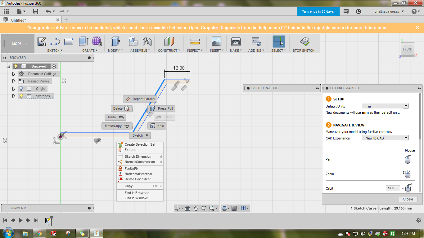
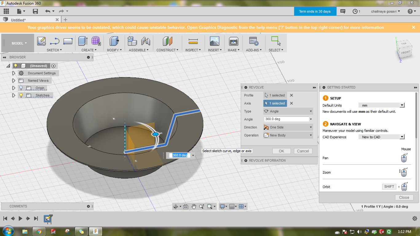
step3..
In this step i extruded the shape fot this i avoided to go through the traditional methods of lofting and shelling, i just drew a shape that could be revolved to make a dish steps included below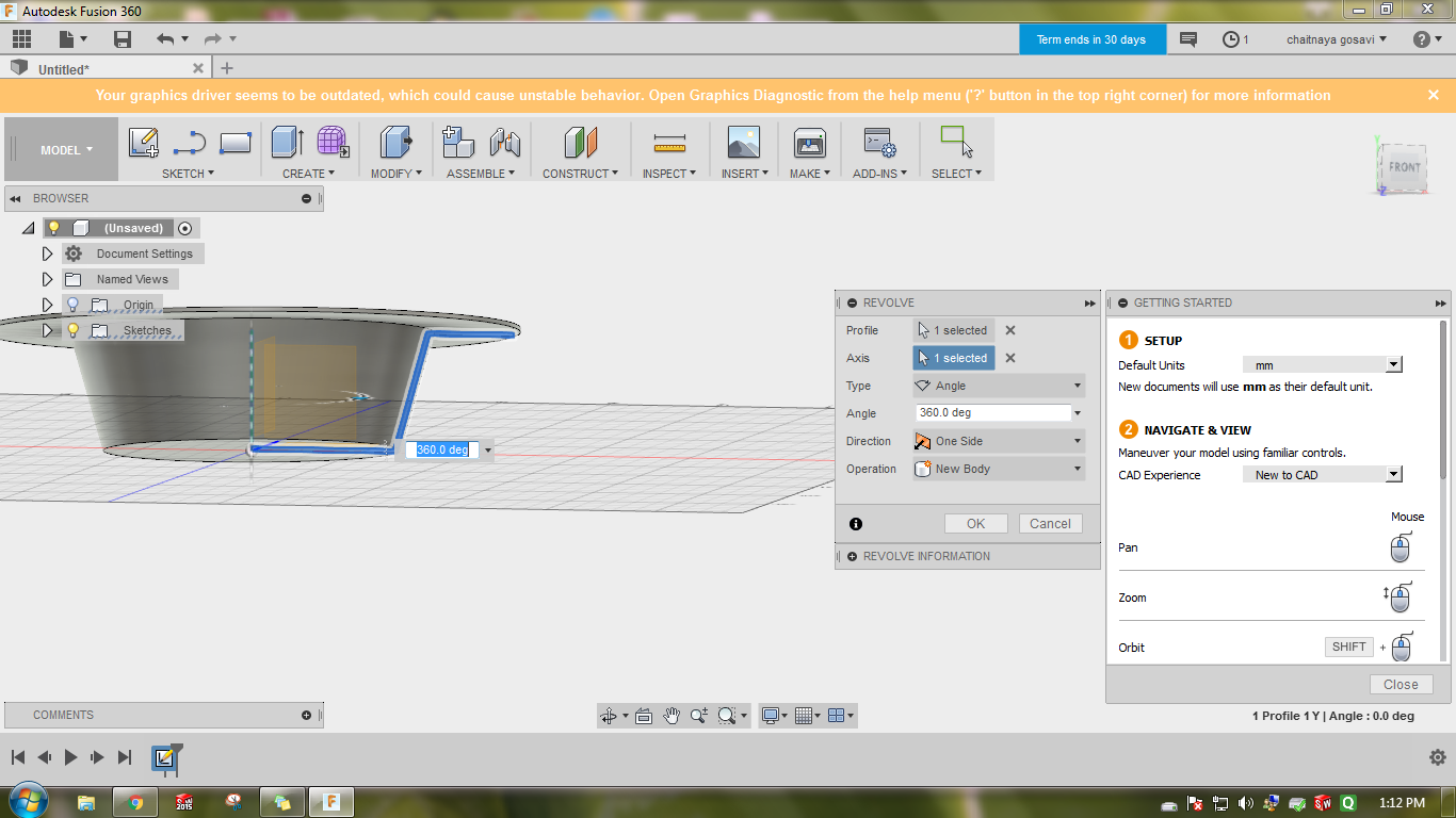
-
Catia
In this sotware I had decided to get the structural design of the hoppers, and the mixer For this i used the basic commands of pad, loft, and cut.
There was a very specific review of mine about this software, it is a very powerful all in one powerpacked software, but it very difficult to operate unless learnt prefectly cause it has a very premitive and poor user interface, which mostly works on commmands and you have nothing on the front user screen unlike other softwares.
Here displayed was one of the assembly that I had sketched about the hopper, Here the commands used a very basic, following listed are the major considerations to be made:-
- To draw a referance plane.:-
This is actually needed to sketch a 2D sketch above another, as I had done here to make a hopper. - The next major function to be considered is the loft funciton (as said in common language), which basically joins two sketches, as in my case the two sketches divided by the referance planes..
Hence working in this softwares was comparatively very difficult, yet i pulled out following designs using same basic concepts as used in previous two softwares the new feature i tried here was the expload command in the assembly section, it basically disintergrates the entire assembly.
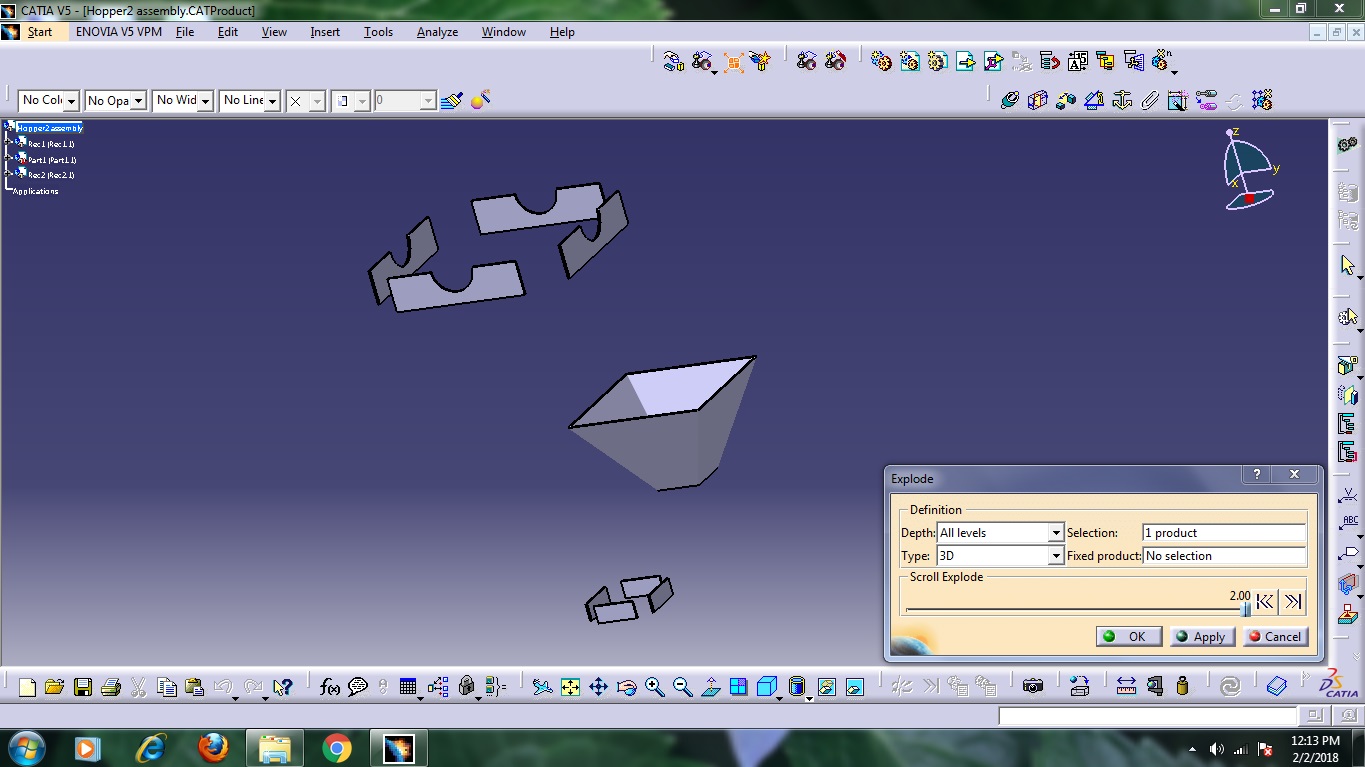
There are two ways to go with this, one is the auto way where it disintegrates it in all possible direction and other is the manual way where u can define which part is supposed to go where once exploaded.
Further I decided to try the assembly of the mixer of my final project the process of which was similar that coud be followed in every cad software. Hence i have just uploaded the way mixer finally looked
That was all i prefered to explore in this section - To draw a referance plane.:-
Task 4:
Simulation Analysis
For this task i decided to go for exploaring the simulation feature
This actually was a new and practically difficult task since I lack the knowledge about engineering
Hence the major problem I faced was to determine what parameters are act needed in my project of it to be judged.
Since I lack theoretical knowledge of all of them
but just in order to test the working I decided to
draw and simulate an arbitrary body,
with arbitrary parameters and analyse the changes and plot my views.
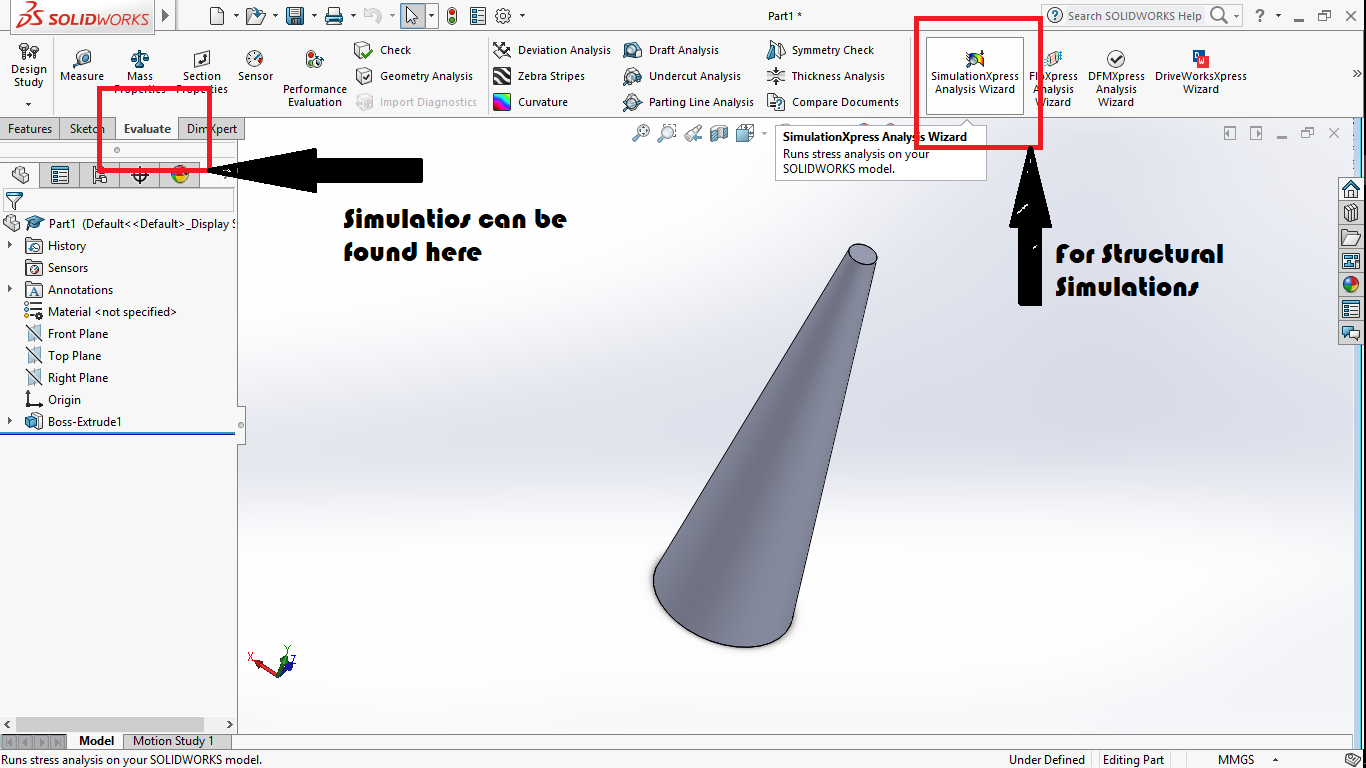
For this i drew an arbitary body, as shown below
Once you click on simulation express, there comes a dialogue towards the right of the design panel , which guides
you through adding the parameters..
1st You select a constraint i.e a refernce side which is to be fixed
2nd You select the load i.e what kind of physical quantity you wish to apply ovcr your body
(in my case it was pressure and force)
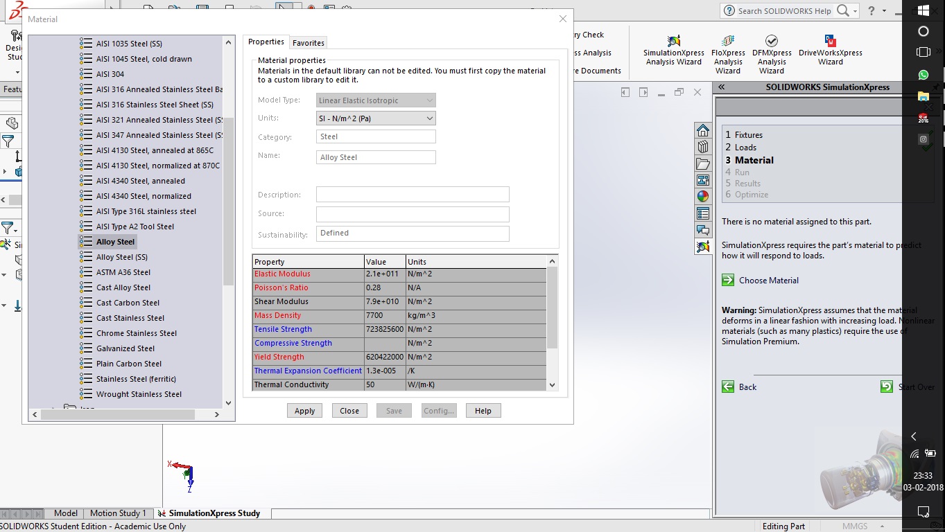
3rd You select the material, for this you have to be very sprecific according to your application and about the properties of your material
(in my case i chose a random material)
4th Then you run the simulation where it shows you animation of the difflection and you get your results which you can monitor
5th Then there is a choice panel for optimisation in which i didnt prefer to rush since i had no knowledge to compile it
but i would be learning through the process of FAB
Following are the analysis for the physical quantities :-
-
Against a force
For this, in order to get a good scale of analysis i fixed the lower end of the body having a smaller base and applied the force on the rest of the body
The force i applied was of 250N on the curved surface of the body which resulted into compression of the cast iron(material i choosed)
The result was deformation as shown below..
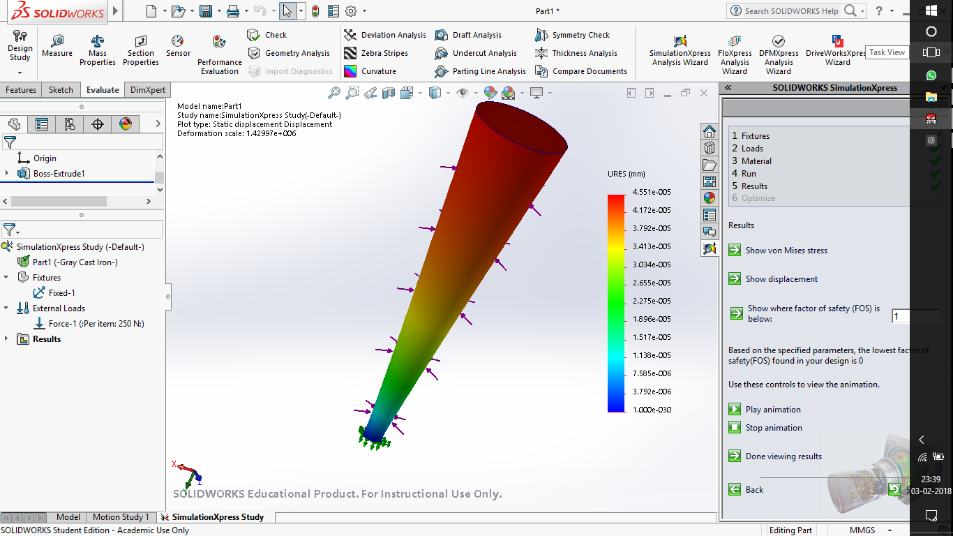
The colour spectrum shows the regions where there is maximum deformation and where it is minimum the highest being the red part -
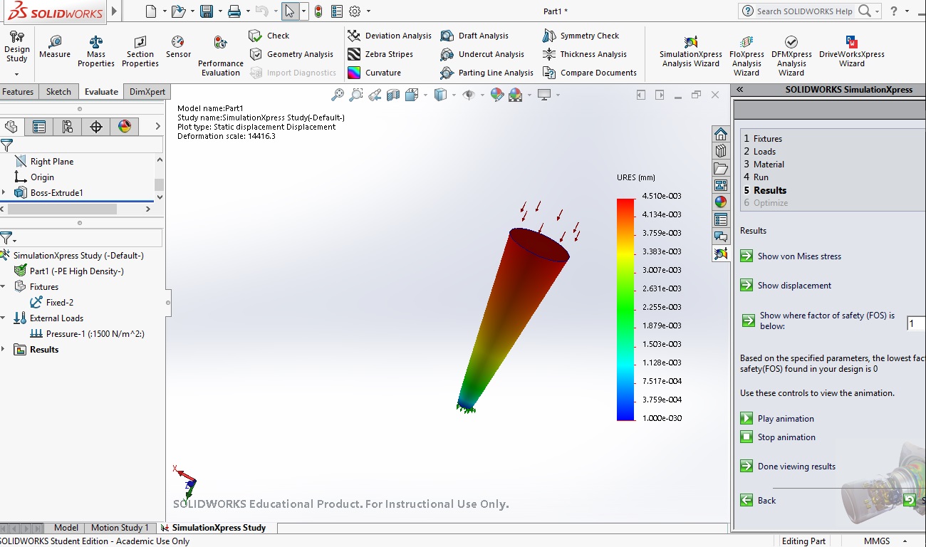
Against a pressure
For this i again fixed the lower part with a smaller dimension and applied a pressure on the upper part The pressure i applied was of 1500N axially which resulted into compression of the aluminium(material i choosed)
The result analysis is again similar the colour spectrum shows the ammount of deformation red being the maximum.
The following body goes maximum deformation at the top portion and the lower par(tip) remains safe Hence as a result the body will be crushed under a force of 1500N except the lower tip which would remain the same
Conclusion
Even though these simulations give you a nearly accurate results there are few more parameters which will addup to the structural simulations to result in different deformations