Aim:
To understand the processes of machining and develop something "Big" using them.
Task 1:
Understanding what is the term "Machining"
Machining is a method of subtractive manufacturing where you cut down the undesired material out of a solid stock of material, unlike casting which includes solidification of molten material into a given form.
These processes are actually required because of the accuracy machines can give, and the rate at which a good quantity of jobs can be achieved.
Following list guides you through the processes under the term machining..
- Turning
- Milling
- Drilling
- Boring
- Reaming
- Honning
- etc..
Out of these, i tried to learn two prosses through this week i.e Turning(explained in project development) and Milling.
Task 2:
Group Assignment:- Analysing the machine
The machine that we were supposed to use was shopbot ___, it is basically a CNC router which works by the the method of milling.
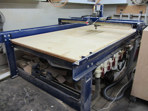
This machine available in COEP is quite of a premitive machine, having an operational software executed over windows XP(which turns out to be a parent source for numerous limitations)
For this we decided to make a few test parts which could test following properties of the machine that could help us design our products efficiently.
- The first and the most important thing we checked was the alignment of the machine, it is basically a Frame body machine, where you haev to install a bed and a sacrificing layer over it(to avoid damage to the bed).
So actually we didn't manipulate the bed allignment all by ourself(as instructed, since if any thing goes wrong its techinically difficult to get a help in India)
Hence we preferd not to play with the alignment.
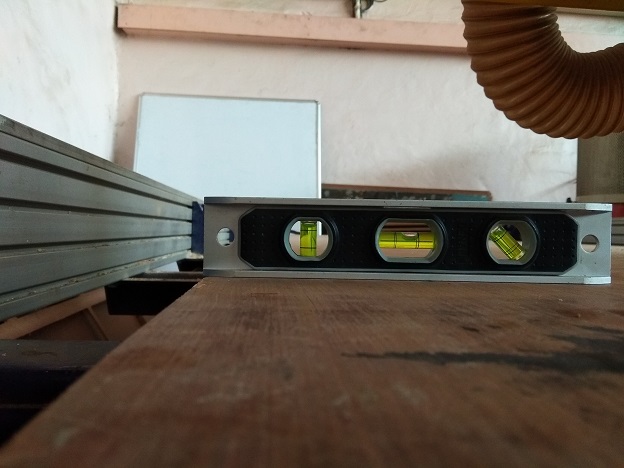
Checking on the spirit level we found a bit of slant in the alignment, but hoping it dosen't hinder too much we moved to get further tasks done.
- The next thing we examined was the alignment of the tool and the way it has to be changed,
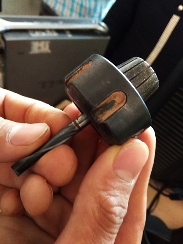
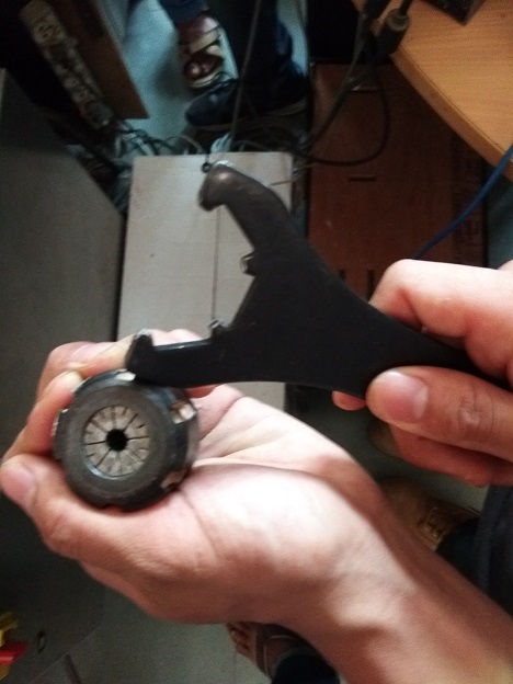
The tool assembly mainly consists of :-
1. A collet:- It is a jaw like structure, when tightend squeases in radially and holds the tool firmly
2. A shank:- The part on the machine body where the collet along with the tool is inserted
3. The nut that tightens the collet
Images as shown below...
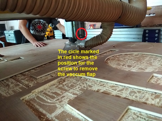
The process for removal is pretty simple:- Initially you loosen the screw of the vaccume curtain, which is behind the z-axix arm, as shown in the figure below
- Then loosen the nut from the shank, with the help of a special groove spanner
- Remove the collet and the tool, replace it with another and re-assemble the collet
- While replacing an exixting tool with a bigger one there are chances of changing the collet too, as it has a fixed tollerance for the size of tool that could fix in
- Hence following was the tool assembly..
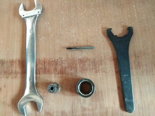
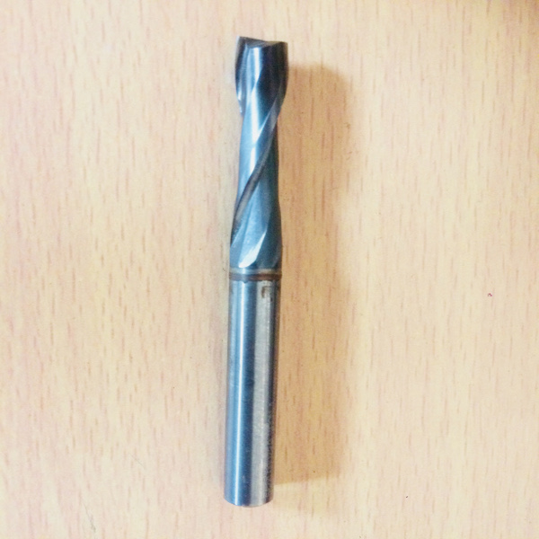
The bit was 2.5mm, flat end, double flute endmill.
- Initially you loosen the screw of the vaccume curtain, which is behind the z-axix arm, as shown in the figure below
- The next thing we learnt was the use of the software, which is described in brief below
- And after being familier with the machine we made a test part to check the finish and dimentional error seen on the machine at varrying speed and feed rate
After milling out the part we got a test part that looked like following..out of which we plotted our conclusions necessary for the design purpose.
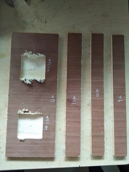
Conclusion:-
- We initally got this output for the pockets
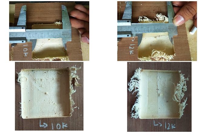
We concluded that the slot that was milled at the speed of 10k had a better finish as compared to the slot milled at a speed of 12k, this was because excess of speed had ripped of the material instead of cutting it. - In the other case where we had milled out the slots, we had got the results as following..
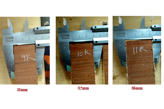
Here the finish quality was quite similar, but a dimensional error was clearly visible as the seen in the image.
The slots were supposed to be of the width 40mm..
The conclusion was lesser the speed is greater the error, hence we decided to keep a standard spindle speed of 12k RPM to and added the errors in the dimensions of our design
Task 3:
Designing and developing our products
For this assignment I had decided to develop a percussion instrument, named as "Cajon", it is a spanish instrument, having a battering panel and few resonant panels, on which you sit and you play.
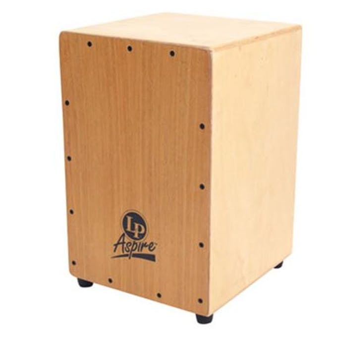
Genrally a cajon box has a single battering head or is has two they are on opposite sides, (makes it easy in terms of manufacturing)
I wanted to develop a cajon box having two battering heads on adjacent sides, this i chose as a new source to design and explore various principles involved.
Basically i decided to make an instrumnet out of this assignment because, i am a percussionist by profession, and for me a good quality cajon has always been a dream, the case is a cajon with a good quality wood is too costly, so considering all these thigs I decided to build one all by myself.
There were few design parameters, that had to be precisely taken into consideration, because while building these instruments there has tp be no air loss from any other place except for the resonant holes, hence the design had to be precise enough, for similar reason I planned not to be relying of press fit design.
Following hence were the some of the key design aspects..
- The frame had to be rigid enough to be able to sustain a load of atleast 100 kgs(considered weight of a human), hence i decided to go with a wood with thickness of 12mm
- Then for a point between the resonant panels and the dry panel it was must to ensure perfect bolting in order to avoid leakage of air, so i decided to make a frixture of pokets and slots, where to exteded panel gets inserted into the pockets of the adjacent panels
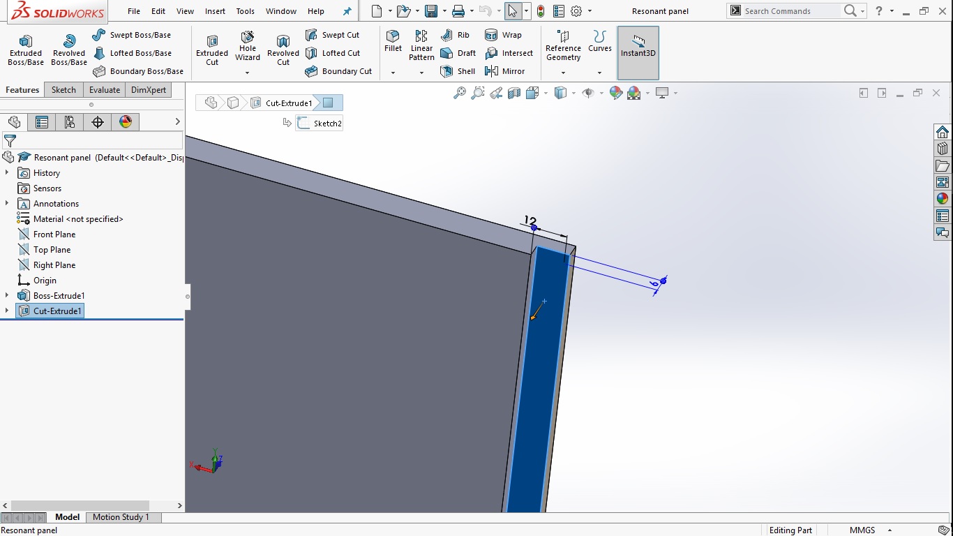
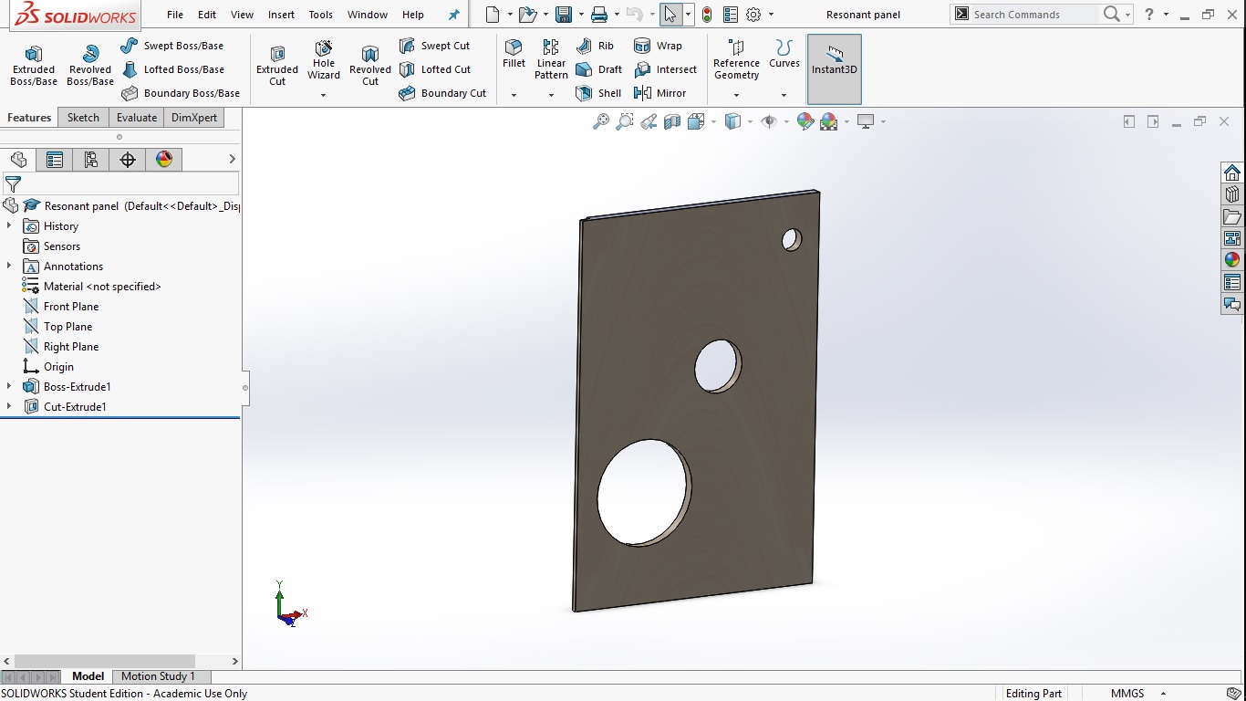
- Then the other major issue was regarding the positions of the holes on the resonant panel, basically the alignment of these holes is a big matter of concern because, if they are ill placed the desired warm sound{A sound having domination of medium and low frequencies} cannot be achieved. Hence after a bit of surfing over the internet, I decieded to go with the following placings for the resonent holes.
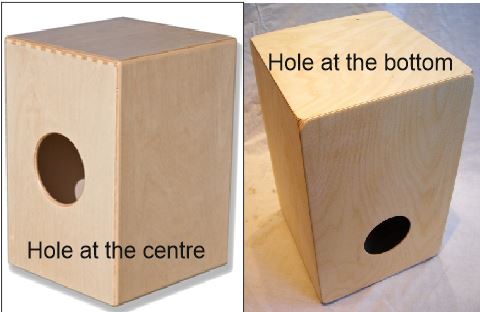
I basically didn't bother to go into much of the theory part since there was a bit scarcity of time, rather I preferd to use a simpler logic of sound, which stated..
If the hole is in the middle you get a greater amplitude and dominant mid frequencies, due to uniformly devided air column between the battering and resonant panels.
And if the hole is off the centre then you get a comparatively lower amplitude but dominant low frequencies.
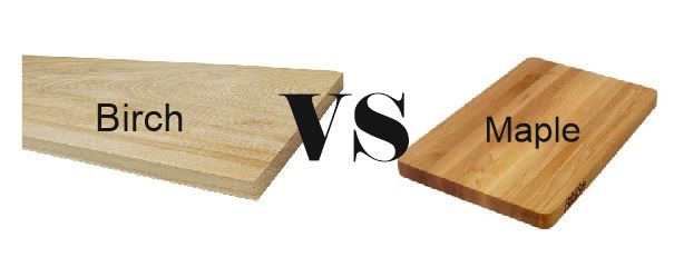
- Then the major parameter was deciding the wood perfectly suitable for an instrument and then viable to process on the machine..
I initially had decided to use maple wood, but finally built the cajon in Birch plywood, due to following reasons- Maple is a hard wood and its actually diffixult to machine hard woods on a premitive machine like shopbot, also we had basic issues of clamping that we were not allowed to bolt the sacrificial layer either
- Maple is basically a solid wood, which has higher density and a fine non porus layer, which if formed in a box structure would reflect all of the fequencies where the higher ones dominate the lower and the middle frequencies
Where as birch has a avid yet compact grain structure which genrates few pores, which absorb the frequencies upto a certain limit to give out a warm sound{Definitly it affects the tone quality.} - The last part is basically about the cost of production maple wood is too expensive in comparison to birch, birch is very reasonable wood at a fair price.
{Note:- Model clearly visible in the "metcap" layer}
And the exloaded view give the idea of how the panels would be assembled
Manufacturing the cajon
The process of manufacturing of the cajon was not so hard I had to cut the designed parts on the shopbot, the major part of concern was the random errors it generated, initially as tested the machine generated a negative(subtractive) kurf of 2mm so I had increased each and every edge of my design by 2mm, since the option for a tool offset was not found.
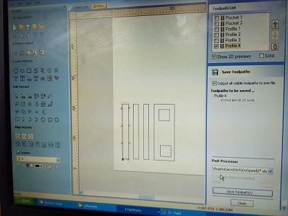
The software that we used for generating the toolpaths was Part works (available on the conputer at COEP), this is a premetive software that runs on windows XP, there are actually advanced tools such as matercam and __

This software is capable of importing file formats such as *.dxf and *.pdf and few more, which are basically vector formats for files.
Hence i converted all of my files to *.dxf format and then imported it to the Partworks..
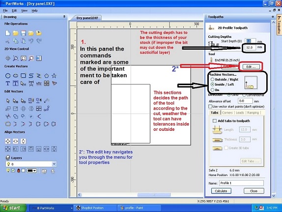
for the process the following set of images gives you a run through
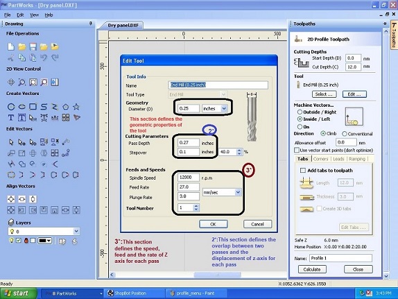
For the machining of the following I had kept the following setting, the image would explain better...
There after the next step was to intiate the machine the process was simple to start of with the main swtich which triggers the control panel and the VFD, and then lift up the emergency stop buttons..
During this process and before starting to work with the machine there were few precautions ment to be followed in order to avoid lethal damage.
- The main thing was to ensure the tool is quite above the bed cause if the releasing of the emergency switch trigger the spindle(usually dosen't happen), then it might break the tool and could damage anything..
- The next thing was to ensure that you have all of the safety gear on as the machine itself dosen't have any cover so its considered to be up with covering the sensetive parts such as eyes.
So its essential to atleast have this basic safety instruments as listed..

- There is one more thing that has to be ensured to be turned on, it is basically the vaccum that is ment to suck all the dust generated during cutting of the wood, if this is not turned of then there are possibilities of having a dust cloud across the lab
- Once the machine is turned of considering all the precautions listed above then the next task is to load the machine with the tool paths that we had generated from part works, it is basically which consists of machine instruction in terms of G-codes and M-codes..
The following set of images guide through the process of loading the work file to the machine..
Problems faced during the process.
The process was quite of a easy task where we just had to load the files desined, considering the errors seen in the test files, to the machine and get it executed..
Yet due to few of the isses there were errors in the final jobs obtained..
Few of the problems faced are mentioned below..
- The initial problem was with the alignment of the job sheet:-
The machine was installed a long time back(as stated) where the bed and a sacrificail layer was glued together and the bed was aligned and bolted, hence now the issue was, over the passage of time and use of the machine the sacrificail layer was damaged and was not at all horizontal,
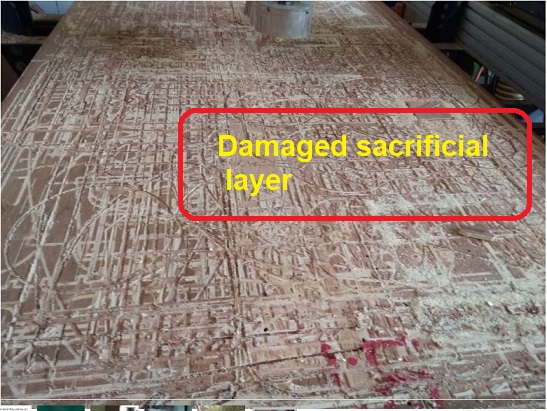
And it was difficult to change since it was glued to the bed..
Hence the stock that we clamped over the sacrificial layer was also eventually miss aligned. This led to problems for pocketing, and maintaining the dimensions - The next issue was with the clamping:-
The issue was due to the damaged sacrificail layer and it being difficult to replace, it was instructed not to bolt the sacrificail layer, which had posed a bigger problem for us to clamp the sheets.
The only way of clamping was to clamp the edges with C clamps,since we were prohibited to bolt the sacrificial layer by the lab where we were working on the Shop-Bot which proved to be well for the initial cuts, but when the material in the middle was removed there was lack of uniformity in the material which made it springy in the middle part, as seen here..
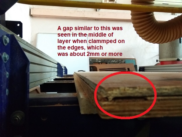
This had caused problem with the depth of pocket, where the dimension was 6mm the machine had milled 7.5mm due to the upliftment of the bed. Since it was only clamped at the edges which was insufficient.
Hence i stuck to my plan got my pannels cut out with what ever error i got, and later after few manual corrections, i assembled it to be looking like this...
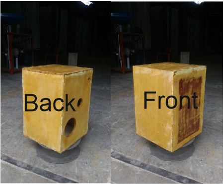
I was very delighted to make my very first designed instrument that too with some different concepts..
.......