Our assignment this weak is to add an output device to a microcontroller board that we designed and program it to do something. The group assignment is to measure the power consumption of an output device.
Adding a LED strip
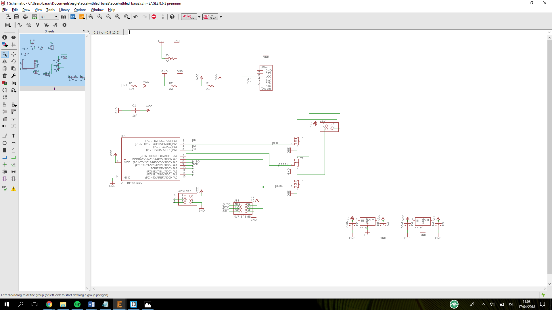
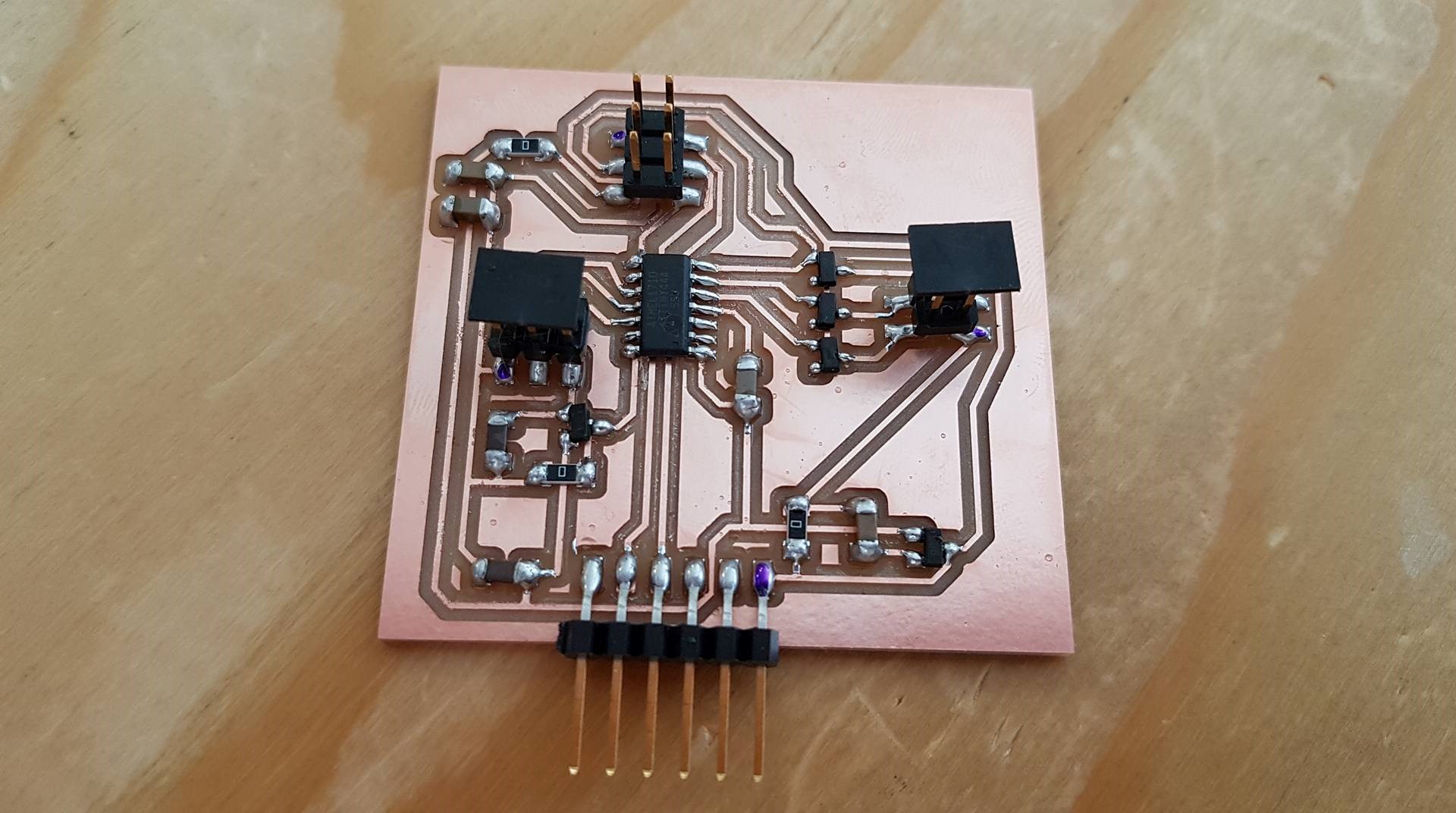
I used eagle to design the board. To save time I added a 4 pin header to my board that I made in the Input week
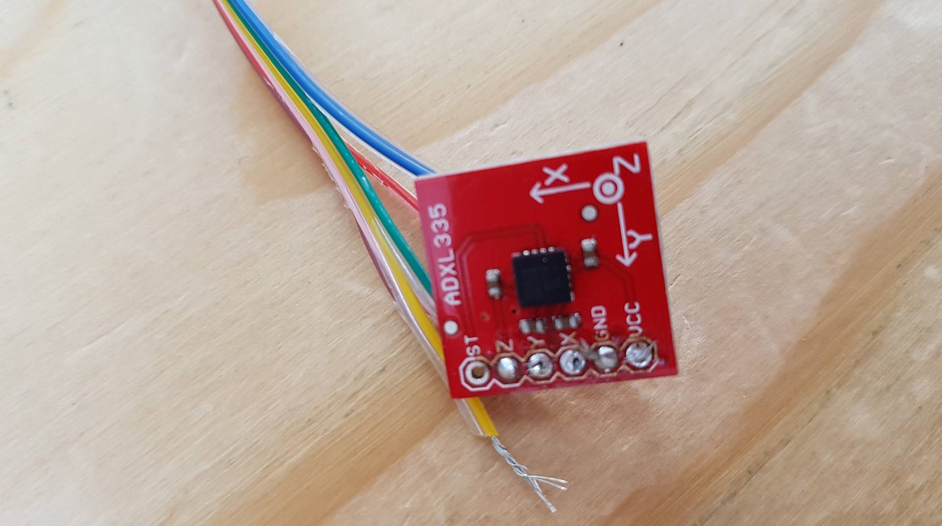
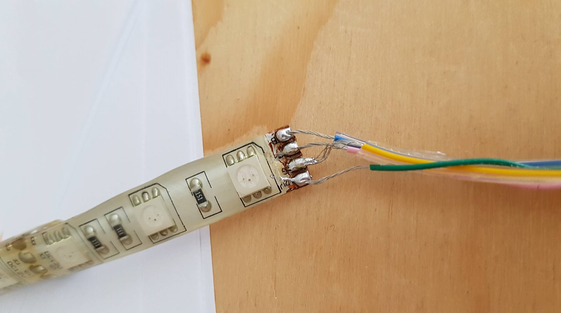
Milling and soldering was not a problem. The accelerometer was an old one that had been used before and the cable connected to it had been riped so I had to clean it and solder the new cables to it. That took some time but it finaly lookes good. I also reused a led strip so I had to clean it and resolder.
Programing is not going well. When I try to burn the bootloader I get the message "initialization failed, rc=-1". Birita told me that the computer couldn´t find my board but it could find my programmer. So now I am working on fixing that. Carl helped me find the problem and it was just that I connected the isp wrong, but when we figured that out we also noticed one of the regulators was getting really hot. It had to be turned over and soldered upside down because it was a different type then the one I had in eagle. Now I got it to program the board but I have to fix the program it is not working to well. I got to programming it and I used Arnars program to work after. It was acting kind of wierd so again Carl came to the rescue. We used the example from arduino for the software serial port. I put the right pins in and changed mySerial.begin to 6900 and the mySerial.printIn to sensorX then it read the sensor for x. however at the serial monitor I had to put it to 1200baud for it to give the correcct reading. Now I have to figure out the range of the accelerometer and fix the code so the light will change colours when the accelerometer.
New board
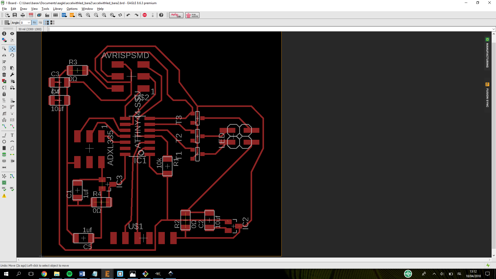
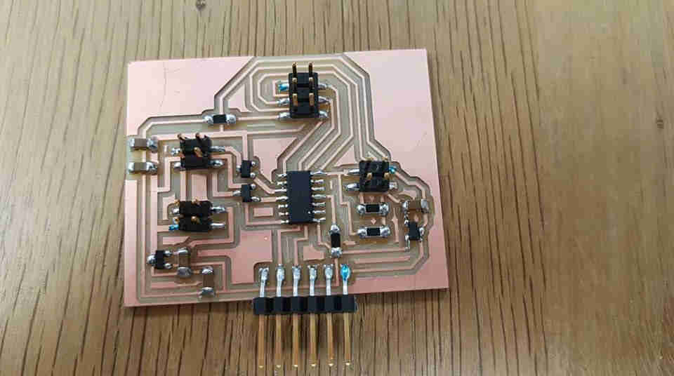
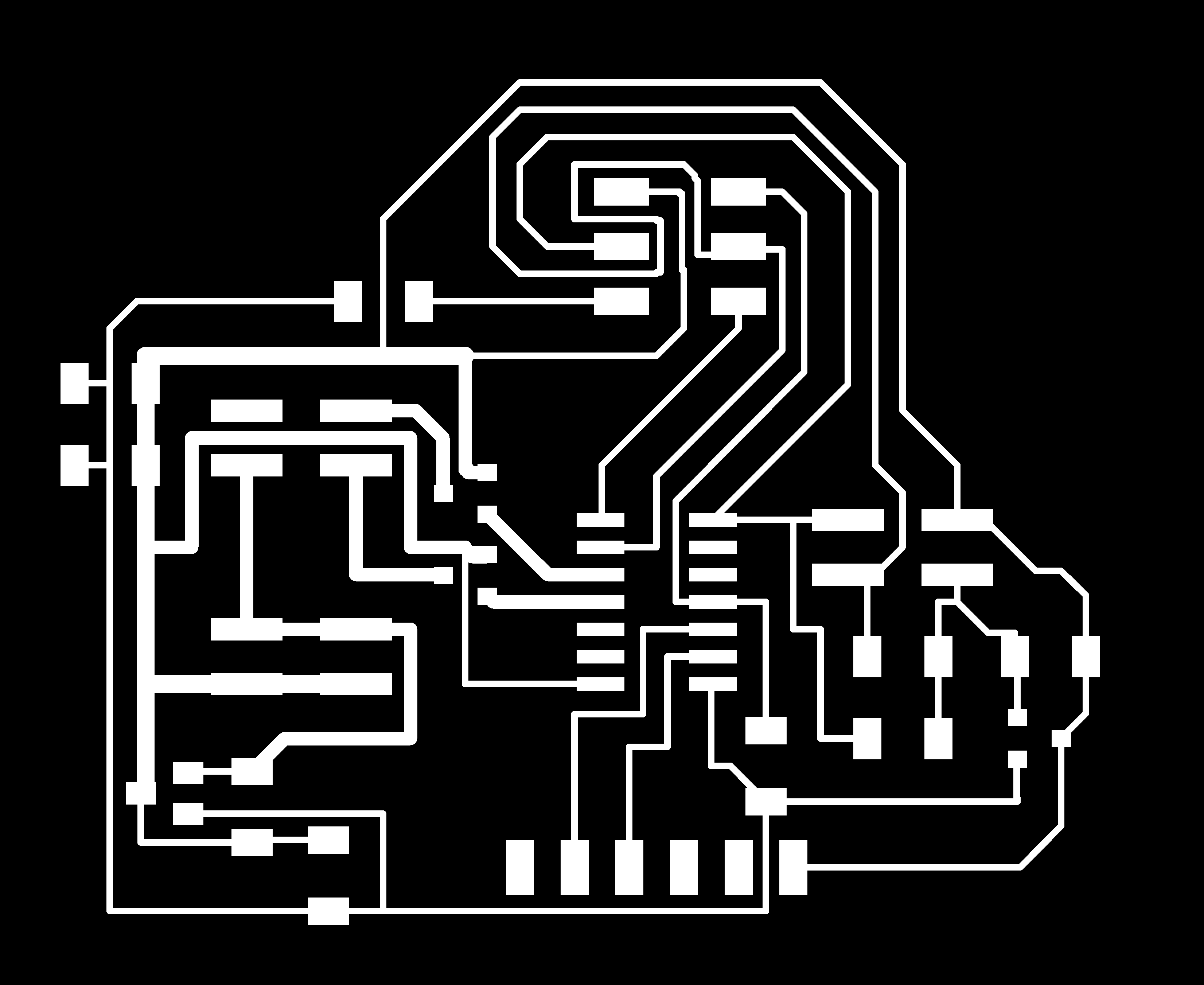
I made a new board that workes with the ADXL435 that I will be using in my final project. It has An LED strip connected to it and I will be using that as my output device. I am using an Attiny44. I used Eagle to design the board. It took me some time to draw it and get everything working but I think it is finaly working right.
I cut it using the modella milling machine and then I soldered it together. I have now soldered a few boards and also milled a few so the progress is pretty quick.
I used arduino to program the board.I will be using millis for my final project so I made a simple program that uses millis to blink the light. For now I just took a code that someone else made and changed it so it would work with my board but later I will use the millis to count how long the accelerometer has been down and after some time it will turn on the LED. I am still working on that code but I know the LED workes and the Accel workes so I just have to get them to work together.
Problems and solutions
I was having some problems with the code and I am still working on fixing that. I decided to make a new board because the one I made before was made for another accelerometer but I baught a new one.
I also had some problems because I was writing the wrong pin number. But now I have the right pin number.
Software I used
Arduino
-For programming.
Microsoft Photos
- For photo editing.
Gimp
-For photo editing and making the outline.
Eagle
-for drawing the circuit board
Inkscape
-For making the outlines.

.png)