The pros and cons of 3D scanning technology
Adventures in 3D scanning
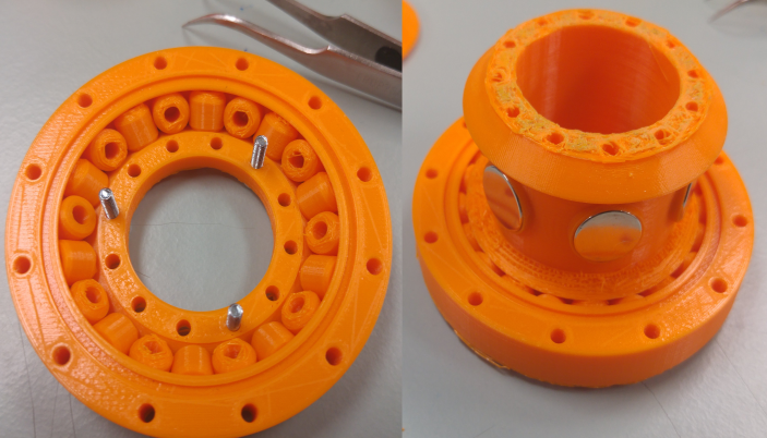
The setup for 3D scanning
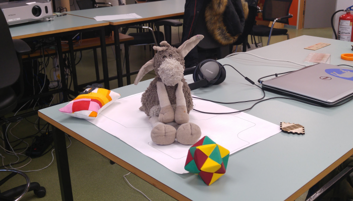
The most easily accessible 3d scanning method is photogrammetry, which uses a series of 2D images to create a more or less seamless whole 3D image.You have to be sure that the background is static, and should place other objects around your target, to help the program correctly align the images. It is more difficult to scan furry objects, and objects which reflect lights will not scan properly, as the photogrammetry software cannot properly process the reflections.
Photogrammetry uses math to calculate the relative position of features in photographs. In order to splice photos together, it refers to where the camera is positioned, and cross references specific easily identifiable features to correctly map out where everything is in relation to everything else.
Always up for a challenge, my target is furry, rounded and uneven, and tricky to pose. In addition, the eyes are reflective. I used various items around the lab as reference points for my photographs.
More on PhotogrammetryRecap
Recap is a part of the Autodesk suite, and offers an easy way to 3D scan objects by using your phone. With Recap, I used over 50 2D photographs which the program used to create the 3D model.
The interface is intuitive, the wait time acceptable and on my first attempt, the program created a usable if imperfect result. One side of my target came out skewed, as if the program had trouble aligning the back of my target properly. This may be due to the uniform nature of the back of my target. Still after using the sculpting tool to nudge the misaligned side back into place and the gap filling tool to fill in the holes, the result is usable for the purpose of printing.
OBJ fileRecap file Get Recap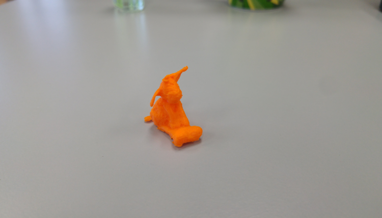
Sheepy
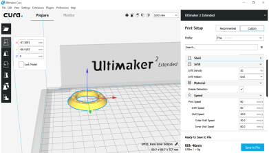
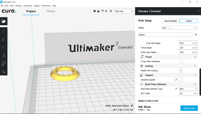
I decided to print the model I scanned using Recap, as it is my favorite of the scans I captured. When I loaded the stl file in Cura, I discovered that the model was seriously tiny. I upped the size by 600% and wound up with a 2,5cm tall model. I printed it using a brim, 25% fan strength for the first two layers and supports touching the buildplate with 1 mm distance to the model. It worked out beautifully, and I can't wait to paint the model.
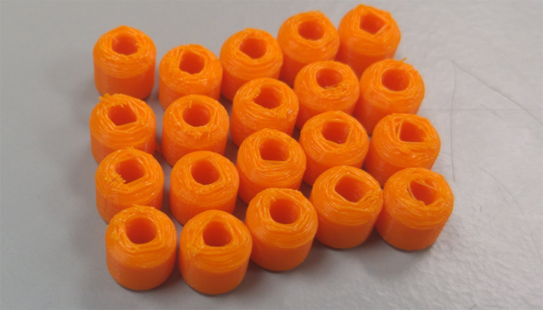
As a sidenote; the above settings were derived from the experience I gained from our group project, where we tested the settings of our 3D printer.
STL file for printing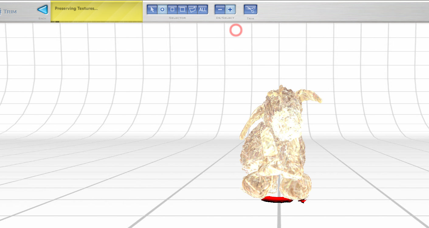
Next Engine
We have a Next Engine 3D scanner in our lab, which uses a combination of images and multi-laser parallel scanning technology to create extremely high-detail scans. The hardware is excellent, and easy to work with. Unfortunately, the accompanying software is extremely slow and heavy, and the gap-filling does not work very well at all.
I did not get a usable scan out of this, as it took up to an hour between the clicking of a button to the execution of the command in the program. Most likely such accurate and powerful software requires a very powerful computer to function properly, and our computer isn't up to the task.
Product website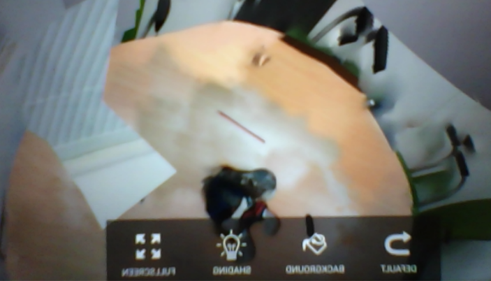
Scann3d
I downloaded the free version of this app to my phone, as it appears to be the highest rated 3Dscanning app for Android, despite only earning 3 stars. The app using photogrammetry, but what is different from the other programs is that this one is in your phone, guiding you as you take your photographs. It guides you by telling you how to start your photo sequence, then overlays dots on the model, which turn green when you are in a good position for the next photo.
Guided by the app, I took about 70 photos of the same model as before, then hit a button in the app which tells it to calculate the 3D model. This took about 15 minutes, including the setup of my workspace, arranging other items, posing the model etc. The phone took a few minutes to calculate the model, which came out completely unusable. The free version of the app allows you to take screenshots, but you can't export said screenshots, nor find them in any image folder on your phone. Hence the very poor picture I took of my screen, which was the best export I could get of this model without paying for an upgrade. In short, this app may be very good, but for a beginner who wants to try it out, it is not worth the time and effort, compared to the much better results gained from Recap.
App page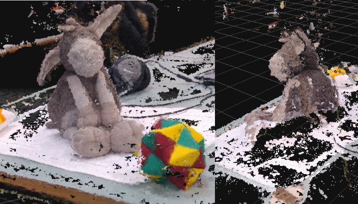
3DF Zephyr
In the interest of comparing software, I decided to give 3DF Zephyr a try as well. I tried the free version, which allows for up to 50 photos. I used the same photos as I used for Recap, in order to facilitate a fair comparison. One of the things I like about this program is that it informs you of where it is in the process. The downside is that the computing happens on your own computer, while Recap does the computing in the cloud. Since your computer is weighed down processing the photos, it limits the amount of work one can do in the meantime.
While the front of the scan worked fine, again there were issues with the back. Possibly because I did not have a good enough arrangement of identifiable objects around that side, possibly because the camera is further away from the target object than it is on the other sides, due to the shape of the table and possibly because of the uniform nature of the back of the toy.
3DF Zephyr page