These are components that interface with the physical world (such as a motor or light bulb), or drives a device which interfaces with the outside world. Neil started the lecture by explaining the safety factors and then went on to explain the different type of output devices and their connections. The last part of the lecture was on how output devices are used in projects.
What is an Output Device?
An output device is any piece of hardware equipment which converts information into human-readable form.
In brief, output unit is responsible for providing the output in user readable form. It can be text, graphics, tactile, audio, and video.
This week I explored display as output and tried to understand LED array.
LED Array
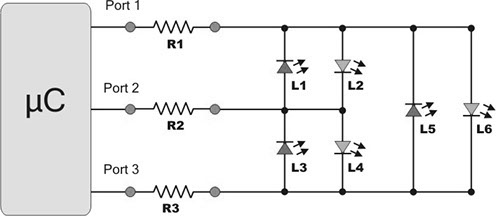
LED array is a predetermined pattern of a number of LEDs mounted on a printed circuit board (PCB) or other surfaces, which is capable of producing light when powered.
These LEDs work in columns and rows. Each of row has a pin connected to it.
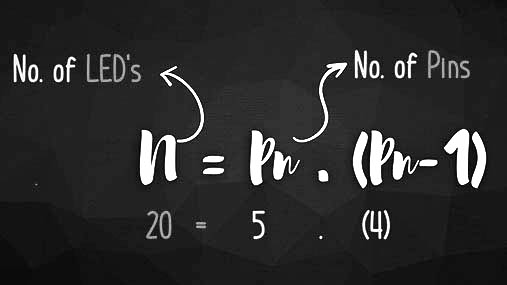
The formula below shows the relation between number of LEDs and Pins.
Each LED is controlled in a different way by powering up each pin separately.
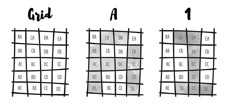
By understanding this we can come with a set of combinations to light up individual lights separately and once that's understood its easy to form characters.
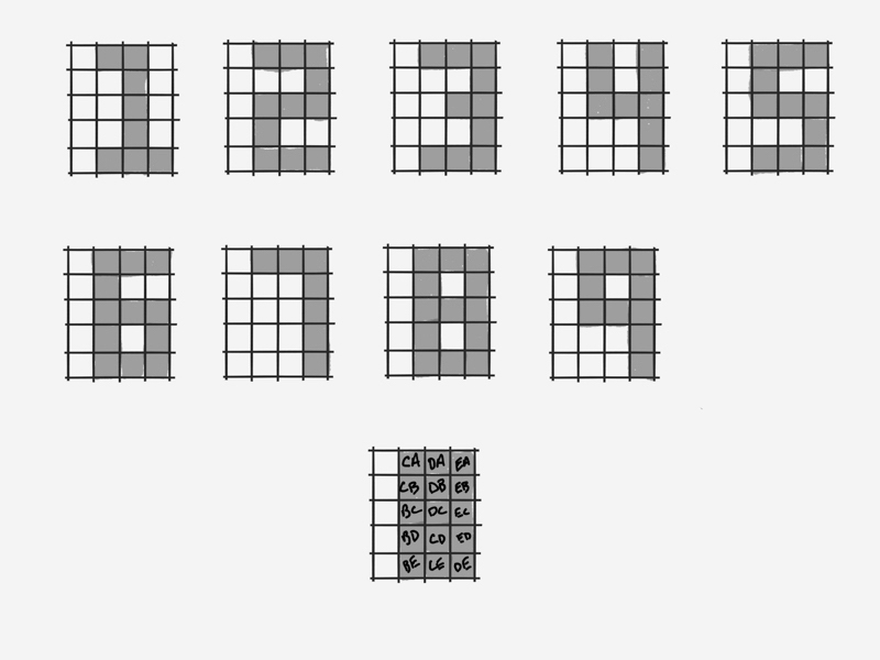
Image below shows how we can find that.
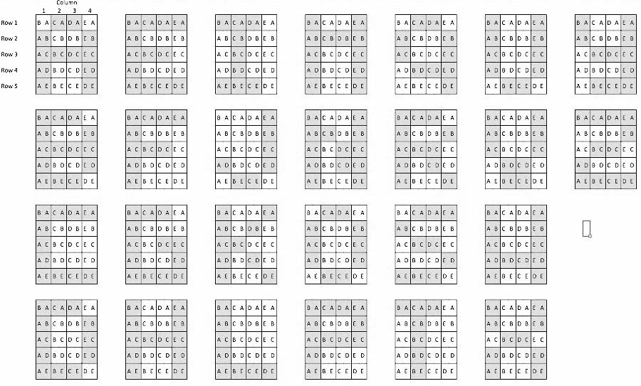
Below is the Grid showing how to make Numbers and letters.
(4x5 Grid)
(4X5 Grid)
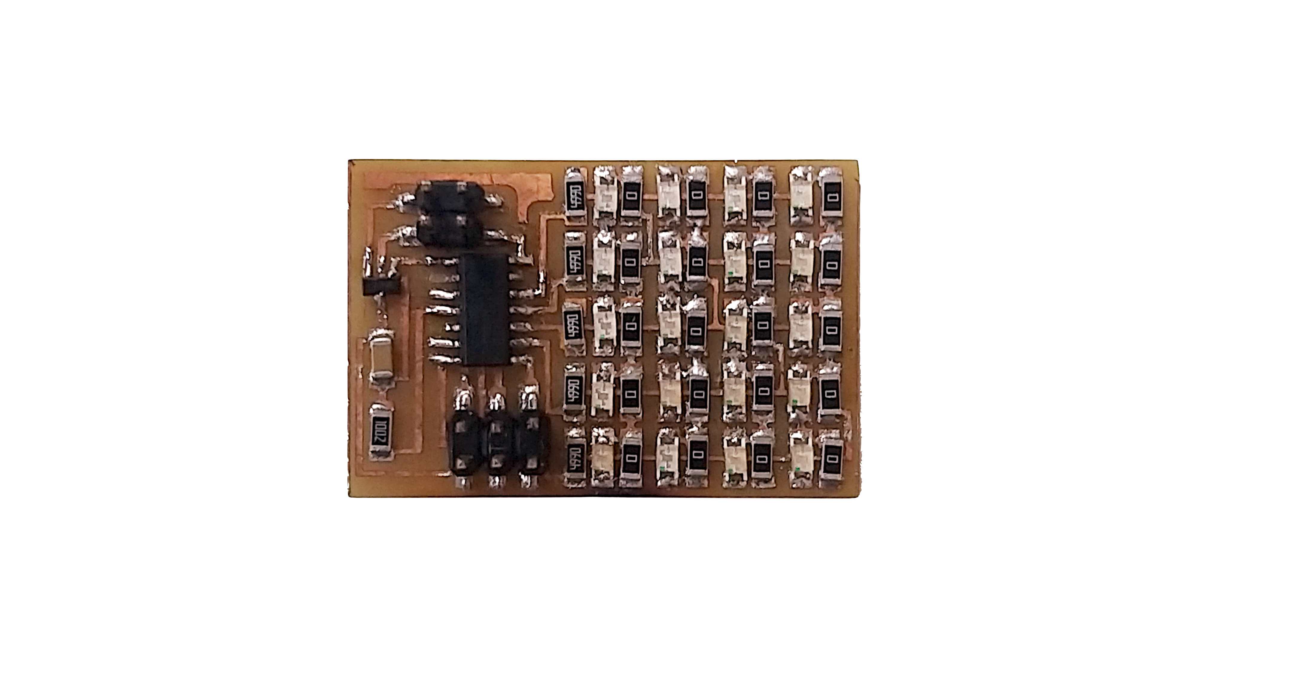
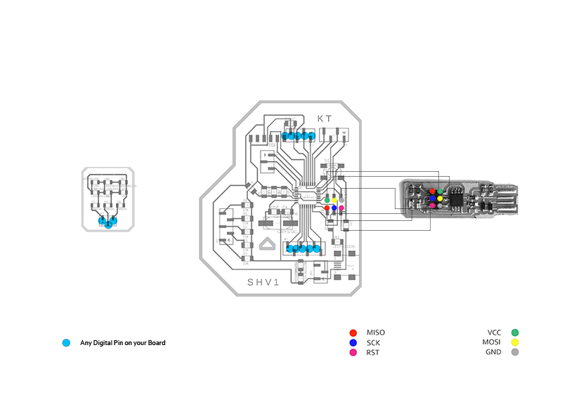
Initially I tested and tried to understand Neil' LED Array Board. I just milled and tried to run it initially.
Below is the board I milled and soldered just to understand.
Making LED Array Board (Module)
Since I already made a board for Input and Output, I didn't want to use Neil's board directly. I wanted to make new shield/module board so that I can just plug it in to my main board and plug it in.
Charlie Pixel - TinyPlex (3x2)
Understanding charlieplex is complex. Thus its always good to learn from basic.
Thus I tried to make 3x2 Charlieplex module. This made me realise that some of the resistors in 5x4 modules were useless.(*refer note below schematic of 5x4 module.)
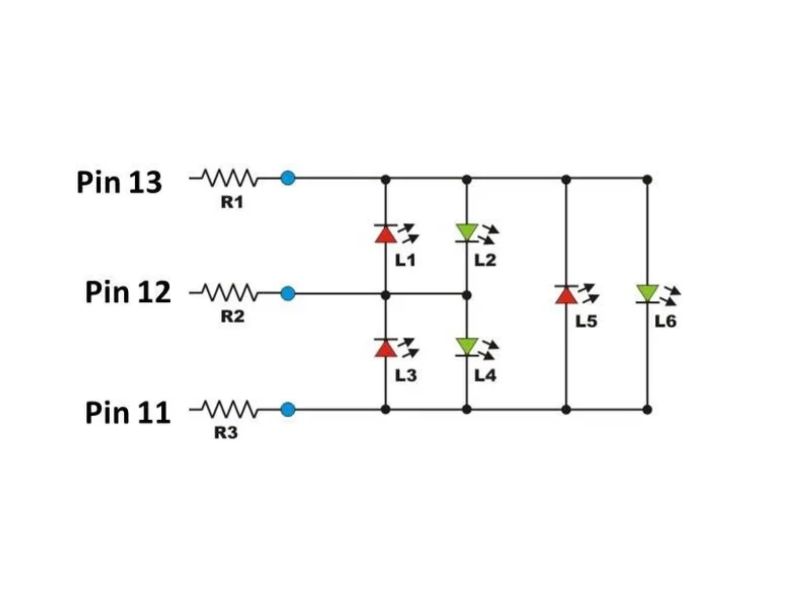
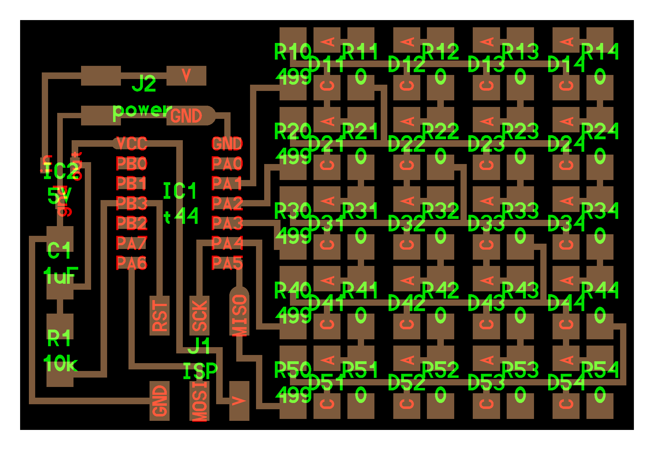
I started with refering schematic which goes as below.
Here 3 pins can drive 6 LEDs according to n(n-1) formula. Where n is number of pins and n(n-1)= number of LEDs.
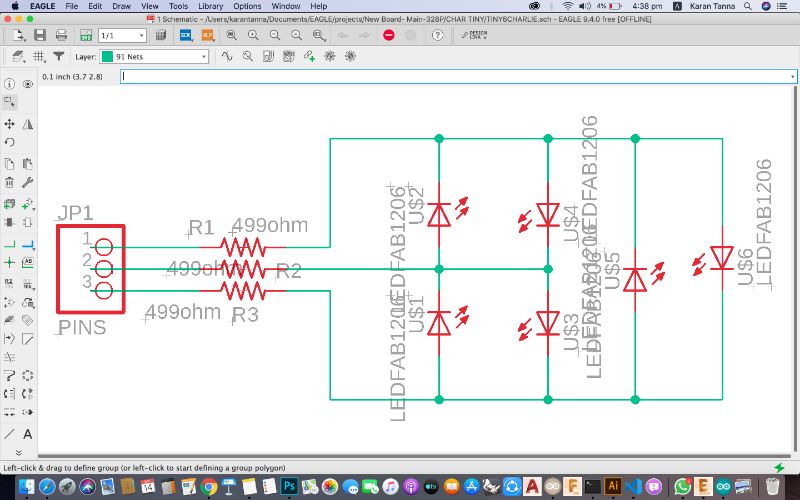
Refering above diagram, I made a schematic diagram as follows.
Components Needed
Component
Value
Nos.
LED
Any: Red, Green, Blue or Yellow
6
Resistor
499 Ohm
3
Headers
SMD
3 pins
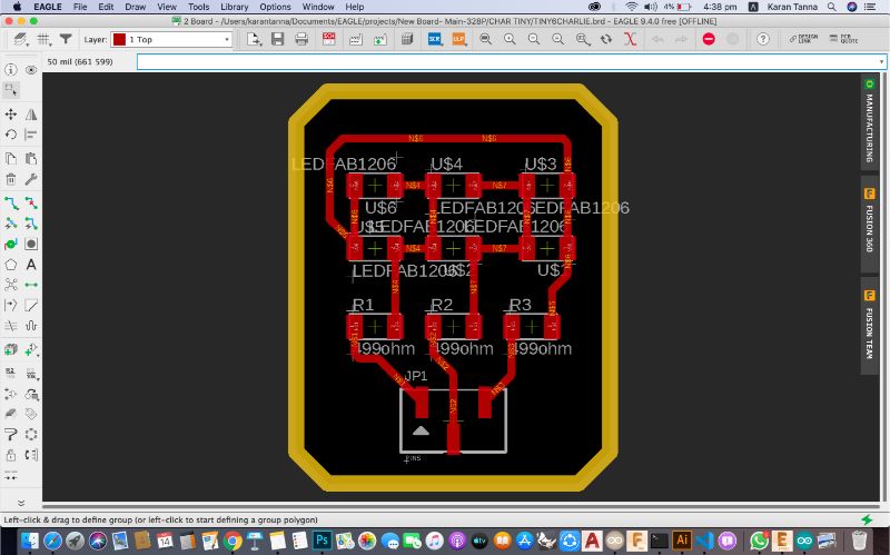
Schematic Diagram
(Here direction of LED is important while making this and soldering it.)
Note : Charlieplexing not only takes advantage of the two states that we normally change, HIGH and LOW, but also uses a third state by changing between OUTPUT and INPUT modes, which affects internal resistors on the Arduino.
Also "high" (5 V), "low" (0 V) and "input"(3rd State). Input mode puts the pin into a high-impedance state,(electrically speaking "disconnects" that pin from the circuit) meaning little or no current will flow through it. This allows the circuit to see any number of pins connected at any time, simply by changing the state of the pin.
In order to drive the six-LED matrix above, the two pins corresponding to the LED to be lit are connected to 5 V (I/O pin "high") and 0 V (I/O pin "low"), while the third pin is set in its input state.
Board diagram of this is quite simple. Board diagram is as follows:
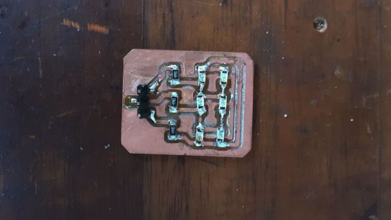
Board After Milling and Soldering
The board above is pretty simple and minimal. The only thing is to be aware about is direction of LEDs. As current flows from Cathode (-ve) to Anode(+ve). Making mistake in one of LED placement could lead into failure of desired output.
Designing the 328p Board
I reffered a very usefful blog by McDude on designing 328p board. He stated some important points about designing and minimum circuit requirements ffor the same.

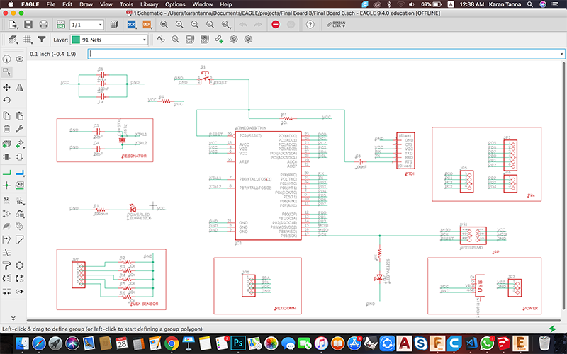
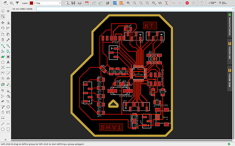