


For this week, we are supposed make two boards of our creation communicate with each other, so what I used my Atmega board that is used for my final project to connect it with a new Atmega board. The final project board is going to take an input signal controlled by a potentiometer. And the other board is meant to light three LEDs of different colours depending on the value of the signal read.
Before we start, let's build some backgorund about serail communication! Our Atmega boards are known as AVR microcontrollers, which use something called USART Serial Data Communication.
The USART stands for Universal Synchronous and Asynchronous Receiver and Transmitter. It is a serial communication of two protocols.And it allow the microcontroller to communicate with a computer(PC) or with another microcontroller (MCU). The protocol is used to transmit and/or recieve data. And this happpens bit by bit. The AVR microcontrollers have two pins for communication, TXD and RXD. T for Transmitter and R for Reciever.
USART has two modes, Synchronous and Asynchronous. And the difference between them is that the synchronous uses timing relationship in transmitting and recieving, while the Asynchronous send the bits one after another with no timing relationship. We are focusing on the Asynchronous mode (UART) even tho the Synchronous communication is advanced and make the reciever job easier, but it needs an additional clock signal while the Asynchronous communication needs only the RX and TX.
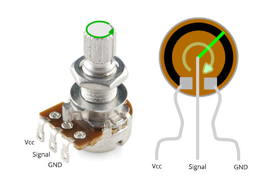
A potentiometer, is a resistance device with three terminals, two termenals are connecting to the high and low voltage, and the middle terminal, which is controlled manually with a rotating pin, is used as a voltage divider, so the output signal would vary as the placement of the terminal.
At first I tried to use an Attiny board, which I later learnt that it has no hardware that suports serial communication and as an Alternative, I needed to use the software serial, which turned out that it takes too much of the memory and is tricky to succeed. So then I made a general Atmega board to use it for this assignment.
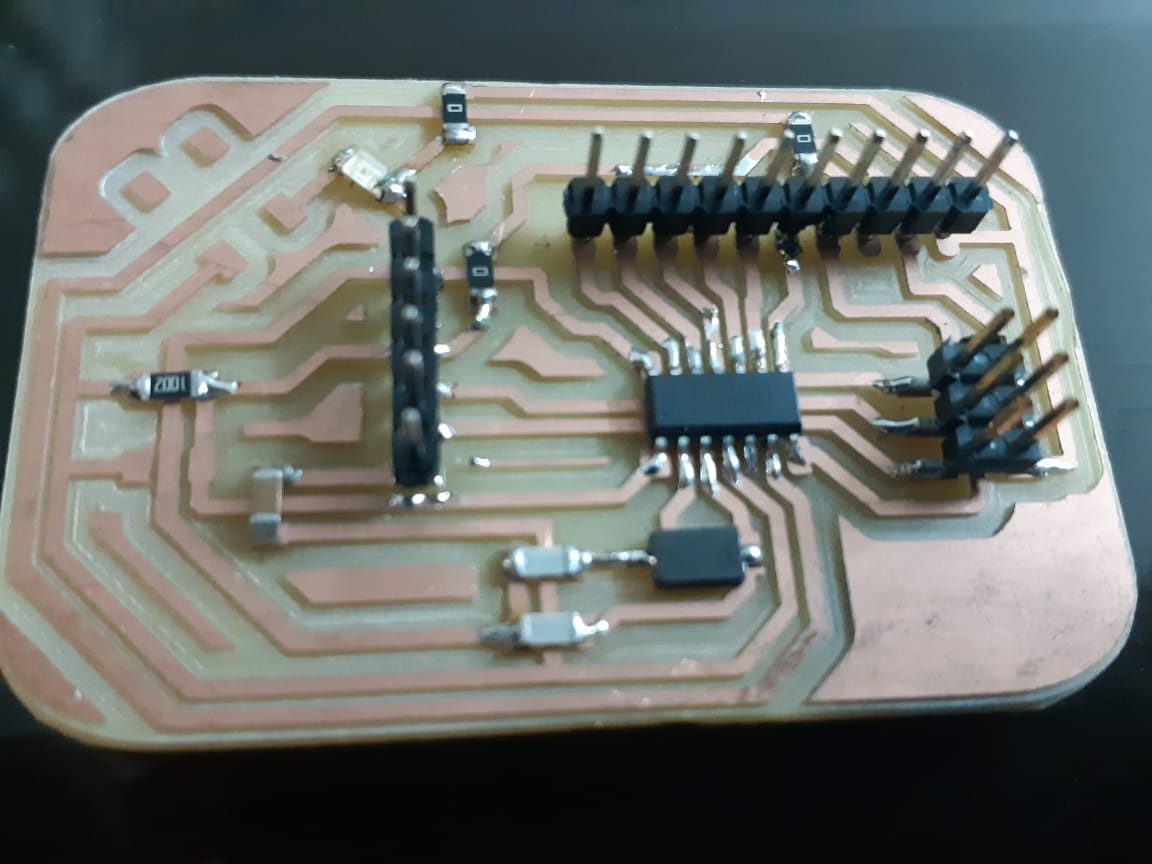
The first Attiny board I made was not going so well, the tracing had problems and I had to make multiple jumpers. Anyhow, after struggling with it and finishing the soldering process, I came to the programming part. And that when I found that I had committed a big mistake; I designed the board for an Atmega 328p, but actually soldered an Atxmega, which have different orders for the pins. And thats when I had to create a different board. And since I am making a new one, I made a whole new design.
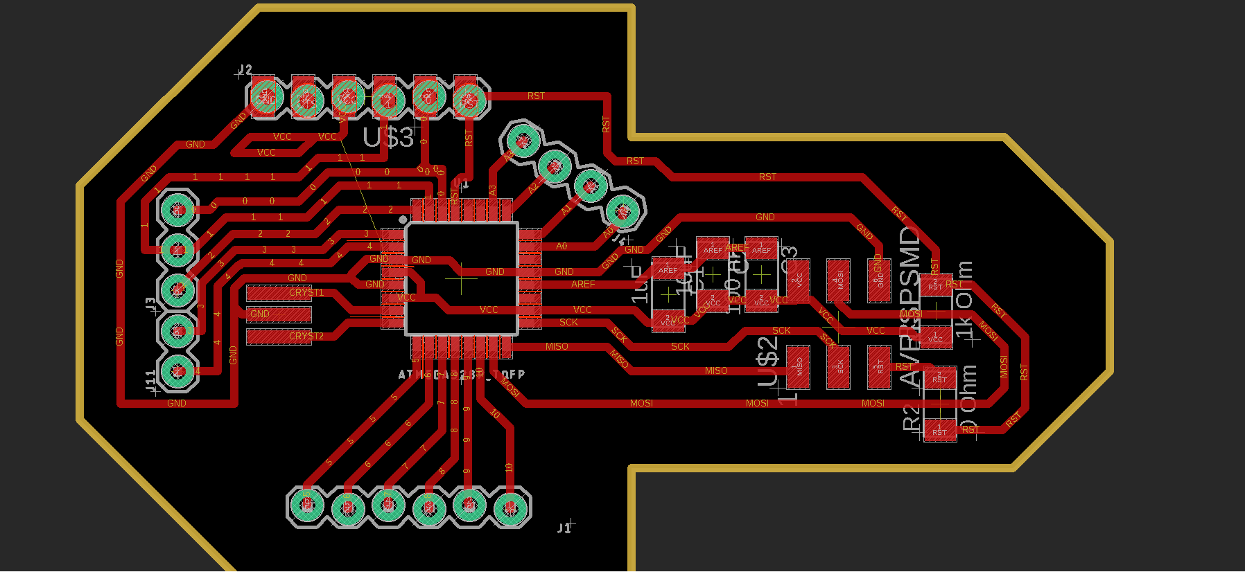
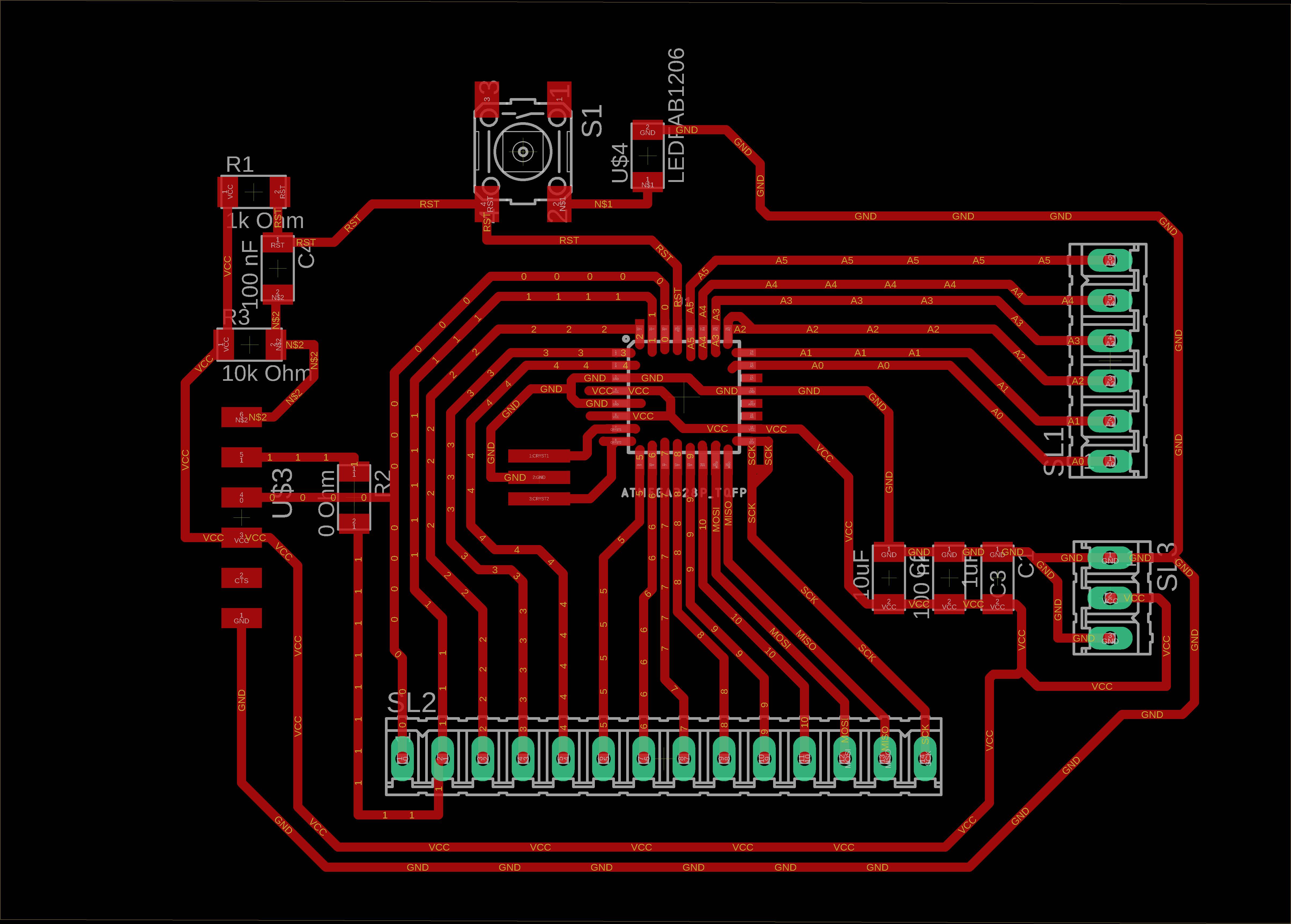
As you can see in the pictures, the design was not so efficient and the traces were milled badly. The board looks so unprofessional and so I designed another one with the following schematics:
.PNG)
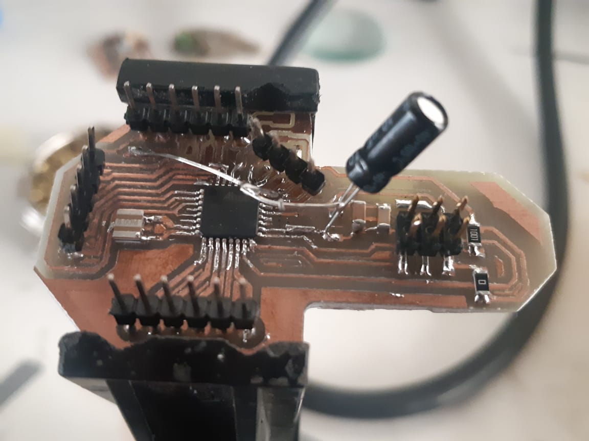
And so the board was created:
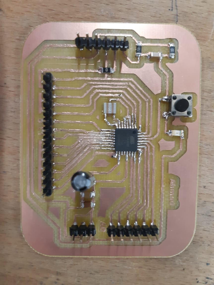
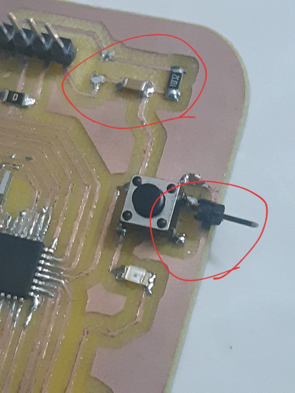
The board, although working, had some problems at first;
The adjustment looked like this:
Programming
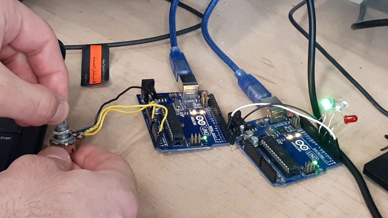
At first, I used two Arduino boards to test and adjust the code. Until I made sure the code was working perfectly, I uploaded it to my Atmega boards.
The code uploaded to the transmitter (the board originally used for the final project) is:
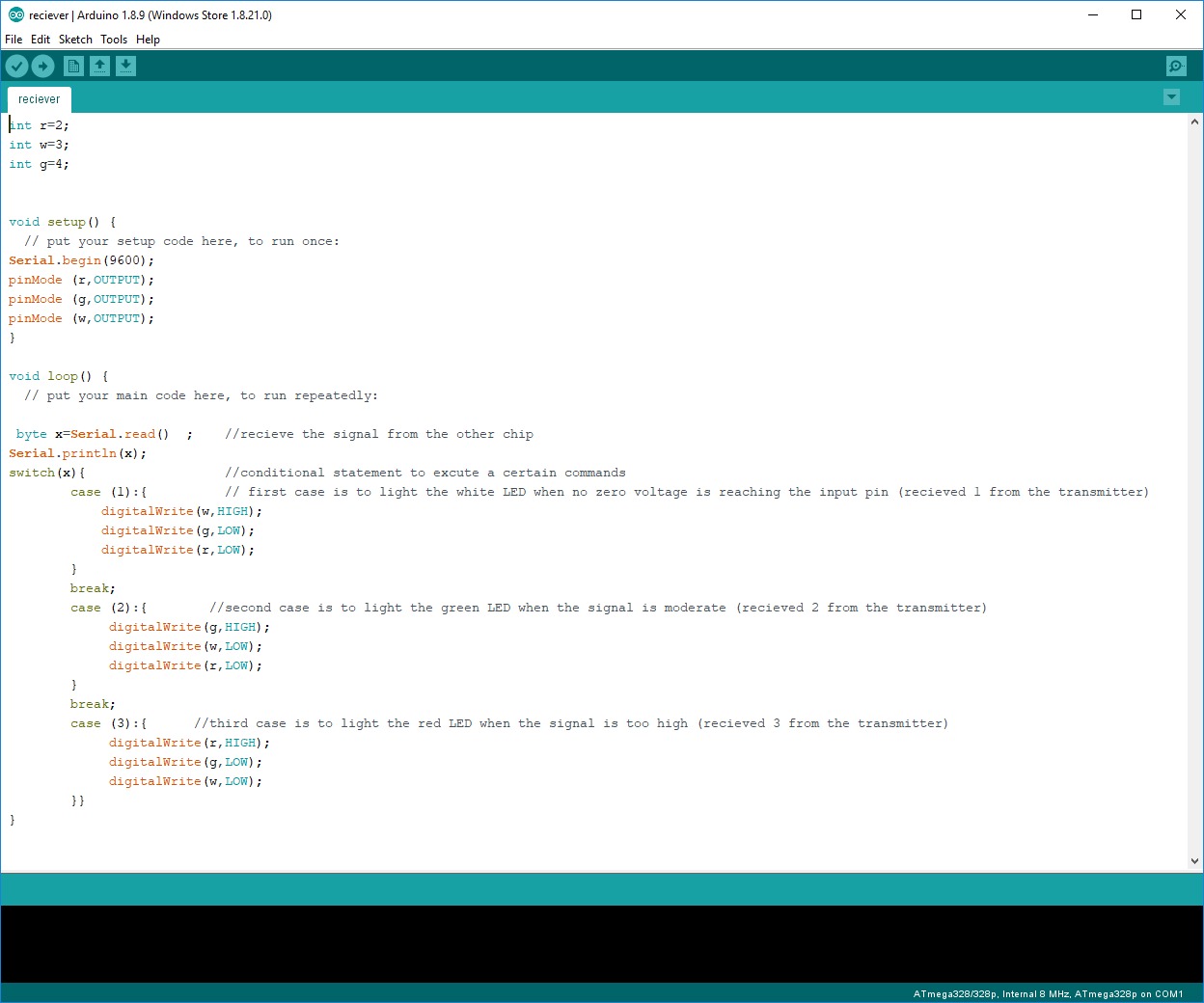
The code uploaded to the reciever (the new board) is:
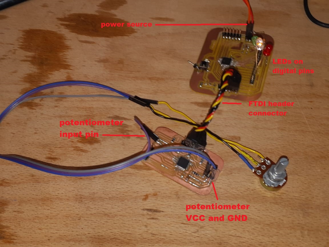
In the same way I connected the Arduinos, I did with my Atmega boards, I uploaded the code to them using Arduino as ISP. Then connected them through their FTDI header. I connected one of them to an outer power and everything went on fine.
Files:
