


For this week, I decided to continue working on the system I created in the Input Device assignment to have the electrical system for my final project ready.
The idea was to take an input signal from a DC motor, and depending on the signal (high rpm or low rpm) the outuput is going to be lighting a building, eather fully or half of it. And to light the building, I used LED stripes that take 12 volts and up to 0.6 A (found that by testing it on a DC power supply).
Of course, my Atmega bourd can not supply a voltage above 5 volts nor drain high current. Exposing the board to such circumstances would ruin it. So I had to power up the LEDs using an external power source, and control them using an electrical switch connected to one of the Atmega pins.
My Atmega board already has 2 digital pins ready to be attached to an output device, those are pin 3 and pin 4.
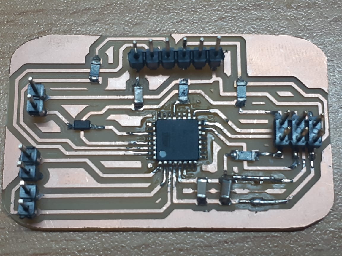
To create the switches, at first I designed a small board with transistors. Then after milling the board, and picking the SMD transistor available in the lab, I figured that it only supports up tp 400 mA current, which is not enough for my circuit. So i replaced the transistor with a mosfet, on the same connection tinking that they have the same properties.
Of coarse, this did not work. The LEDs got turned on regardless if a signal was sent to open the junction switch or not. And then I was aware that I had to design a different board.
I had to study and gain some knowledge about Mosfets to learn how to use them...
Mosfets are similar in a way to transistors, as both of them can work as an electrical switch. The main difference in their mechanism is that the transistor turns the circuit on when a signal is sent to the base. The signal is a current. While in the mosfet, it turns on when a voltage difference is applied to the gate. Meaning there is no current drainage from the control circuit. For this property, mosfets are great for large current flow.
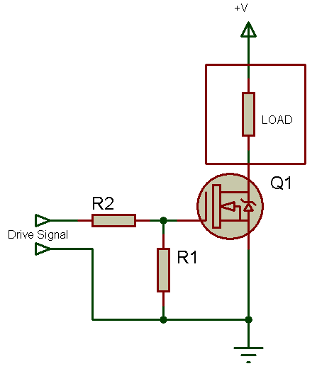
Anyhow, since the gate is highly capacitive and might draw a big instantaneous current, we should place a small resistor in series with the board when connected to a microcontroller.
When there is no voltage difference between the gate and the source, the resistance between the drain and the source gets very big making it like an open ciruit. But when we apply a voltage difference between the source and gate, the drain-source resistance gets reduced, making way for the current to flow.
To make that applicable, we'll place a high (pull-down) resistance between the gate and ground. And the source to be connected to the gorund directly.
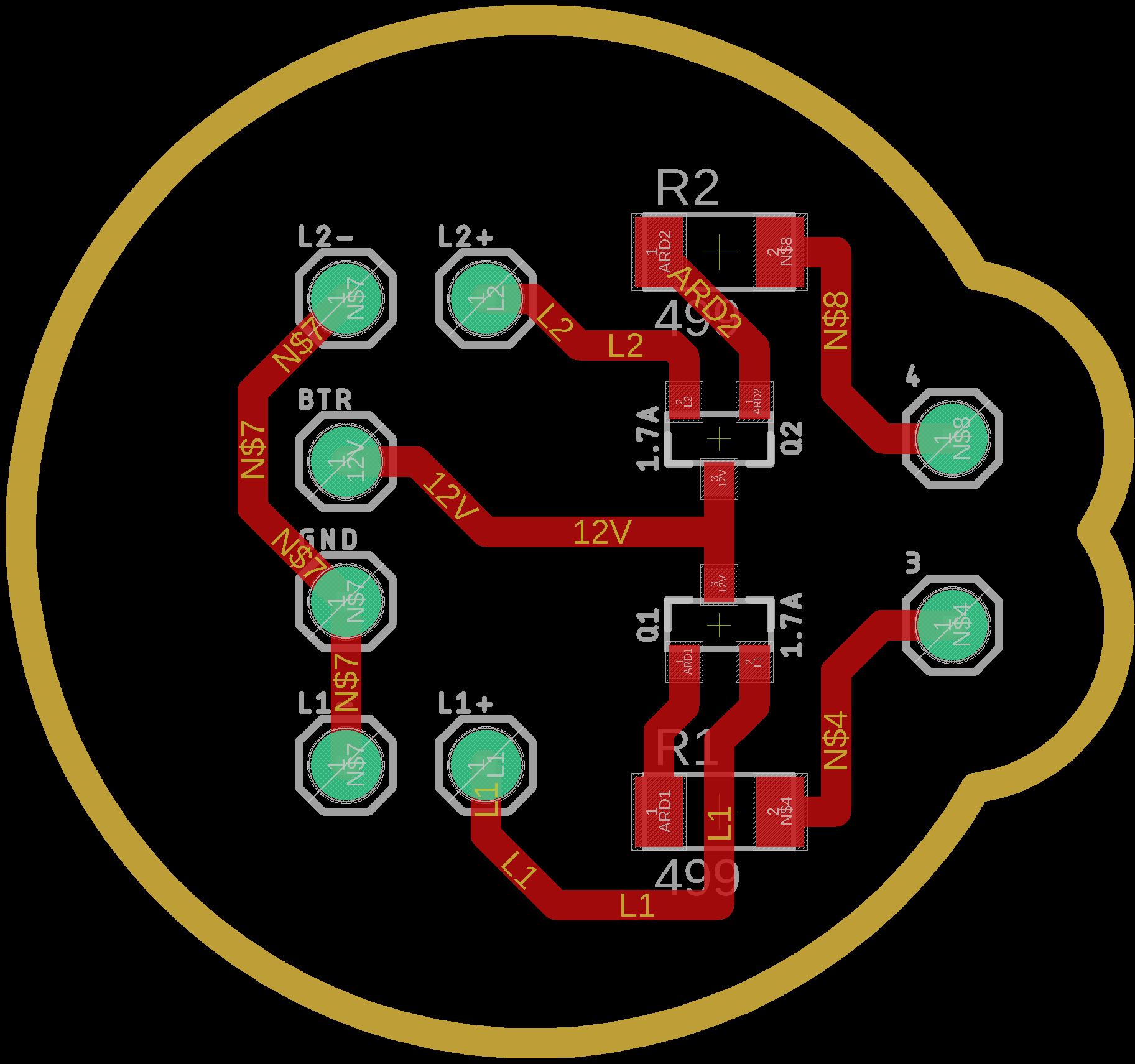
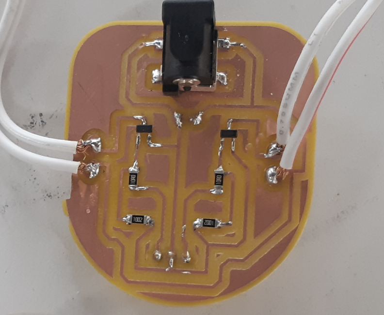
Hence, I created this schematic:
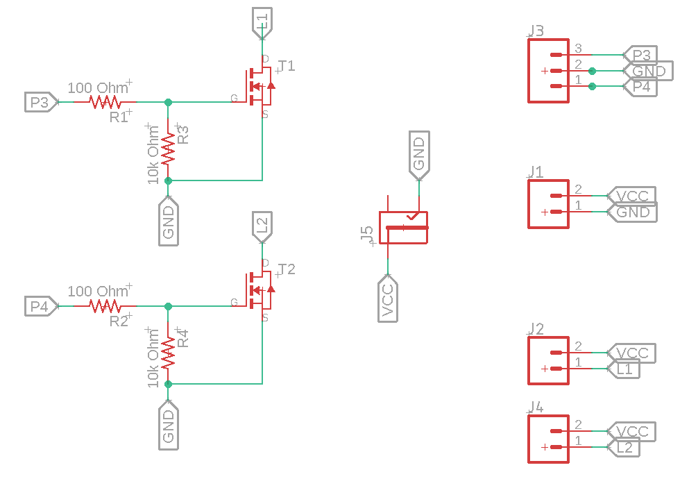
I used the power jack so I can power the LEDs using my lithium battery. An important thing to put in consideration before selecting the polarity of the jack is to test the polarity of my lithium battery, because I don't want the positive terminal to be connected to the common ground and the negative terminal to the high voltage trace, but the opposite. So to test it, I used a multimeter.
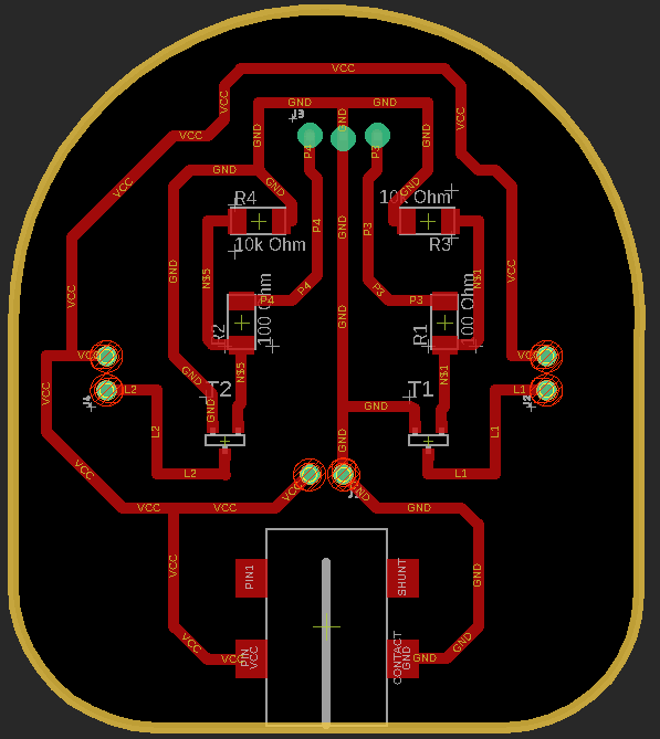
Notice the way I placed the pins connected to the board; digital pins 3 and 4, and the ground. I placed them in a way so that I can connect the mosfet board to the Atmega board as a shield.
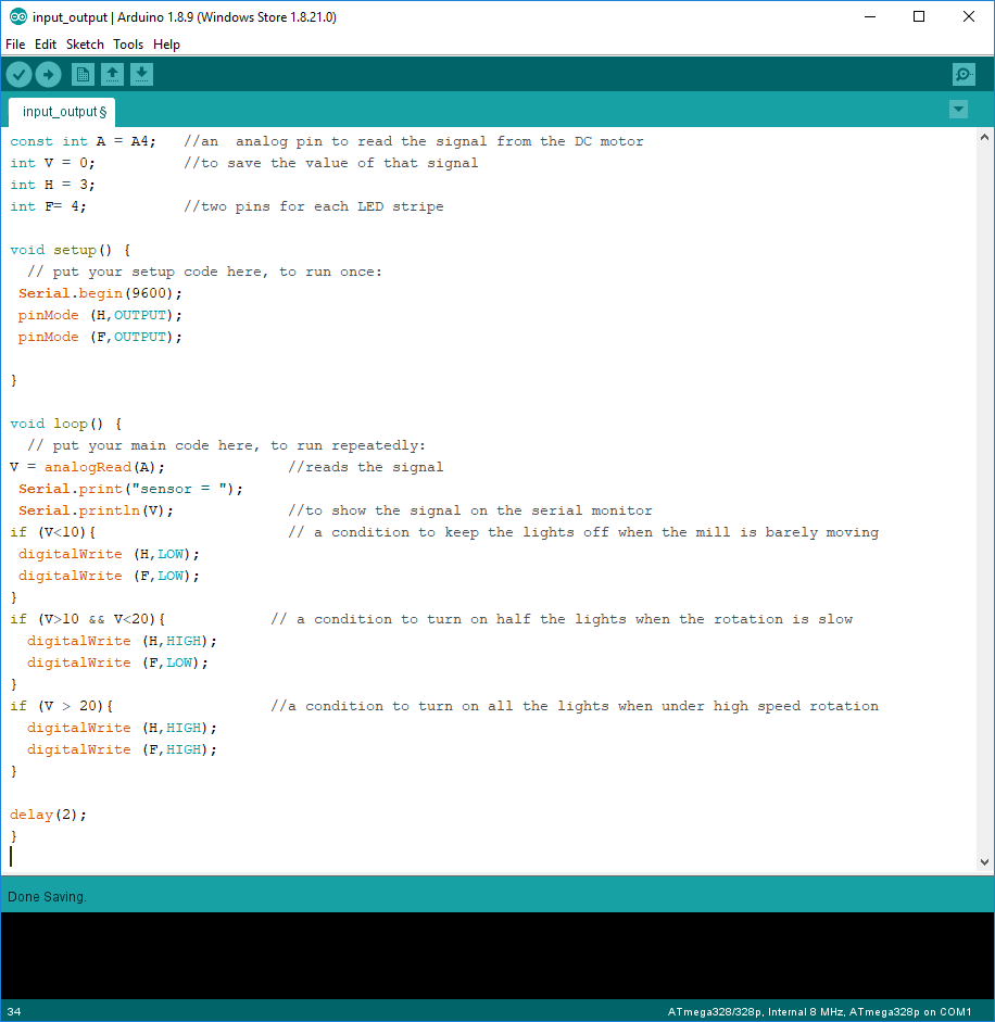
Arduino IDE
The code I used to run the system is an update to the code I used for the input device, and it goes as follow:
---
An important note: Althought the LEDs are powered by the lithium battery, but the Atmega board is still powered from the computer because it should not take more than 5 volts, while the battery is 12.4 volts. If I want to power my system completely on the battery, I need to create a voltage regulator chip between the battery and the Atmega board.
***
Files:
