measure something: add a sensor to a microcontroller board that you have designed and read it
probe an input device's analog levels and digital signals
For this assignment I decided tomake capacitive touch switch using Capsense library of arduino. Capcitance touch is also a requirment of my final project.A capacitive switch is a type of touch-controlled electrical switch that operates by measuring change in capacitance. It works in the same manner as a typical capacitive smartphone: when you touch the surface — assuming you aren’t wearing gloves — a small electrical charge is transferred from your body to the switch, which subsequently causes a change in capacitance. The switch detects this change, responding with the appropriate command..Source
capacitive Touch
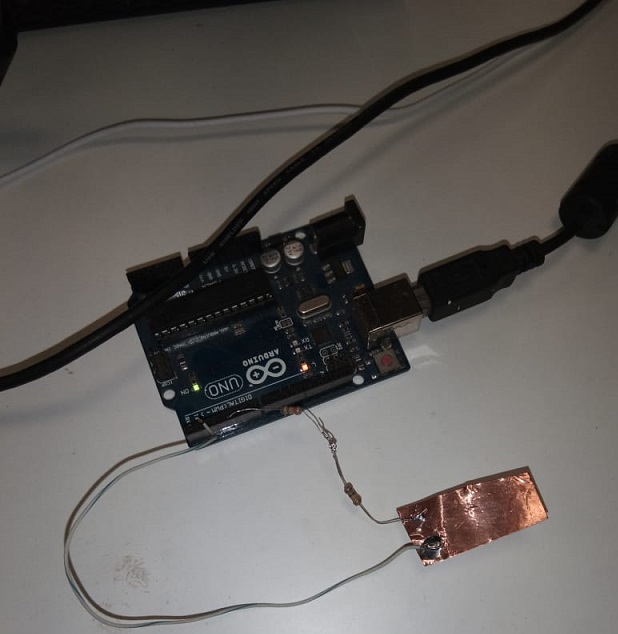
Initially as experiment i took arduino uno and connect one resistor and wire and make connection to arduino uno.I Found this helpful video from Youtube
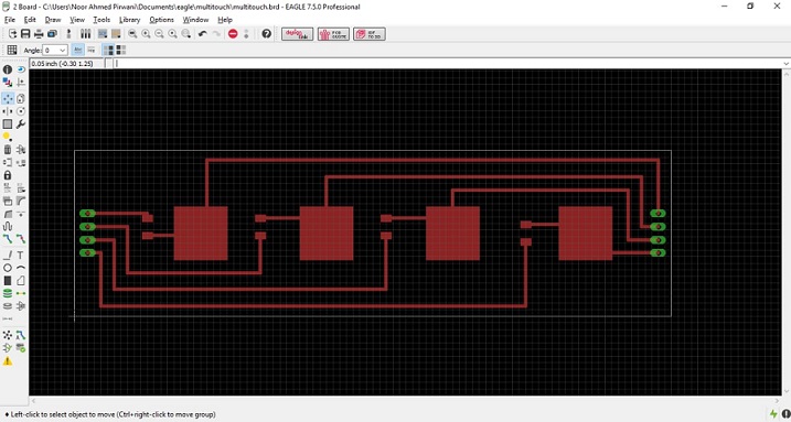
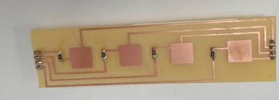
I have designed the PCB by conserding the requirment of my final project. All the components connected will be use for my final project. Following image shows the circuit.
Buttons
After designing the PCB, next step is to generate RML files for rolland SRM-20.
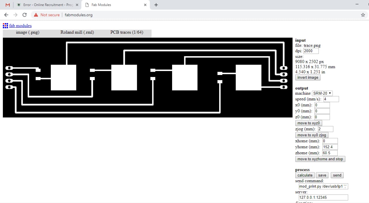
Generating Rml
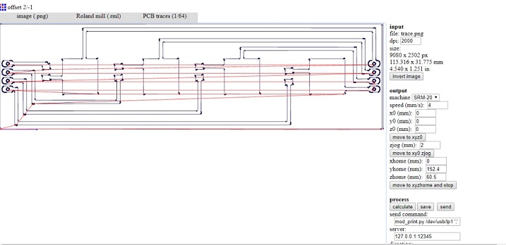
Calculating Path
R1, R2, R3, R4, = 4.99 K OHM.
2 SMD male header 1x4.
Capacitive Switch Buttons
For programming I Used CapSense library to create a simple capacitive touch switch with the Arduino Uno that I made for output week Assignment sasktakit. Intially I download Capsense library of arduino , You may download library from Here
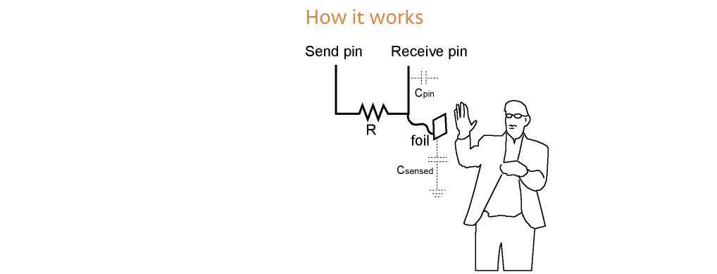
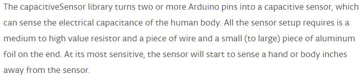
I read some documentaion about this library from where I got the idea how it works , Connection with arduino and some applications of Capacitance sensing
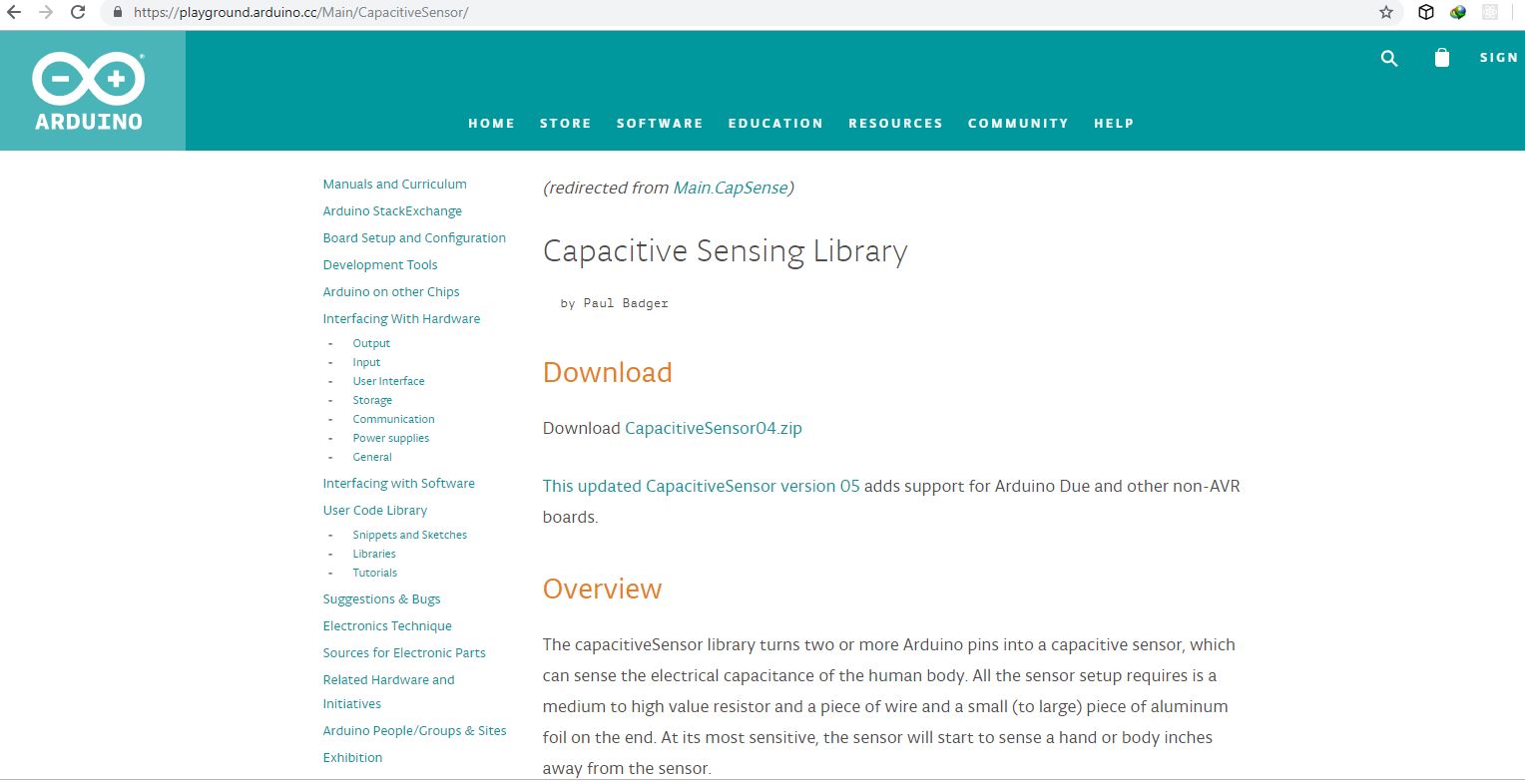
Downloading Library
Capacitive Switch Buttons
Connection With Arduino
After Soldering The board the next step is Programming the board in my case I used my Sasktakit that i have designed in Week12 for my final project.
I used Capsense Library of arduino and program my board
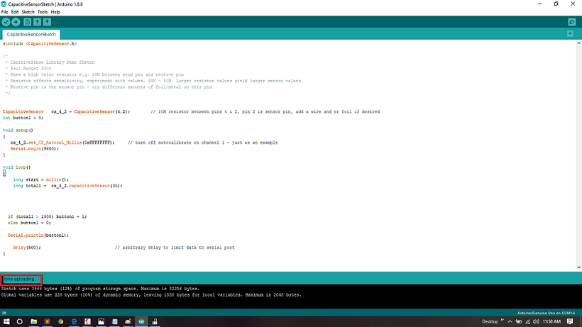
Done Uploading
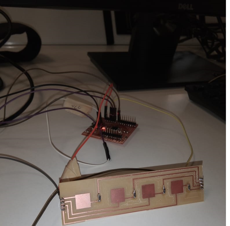
Making Connection with Board
For Connection I used pin2 and pin4 of my board
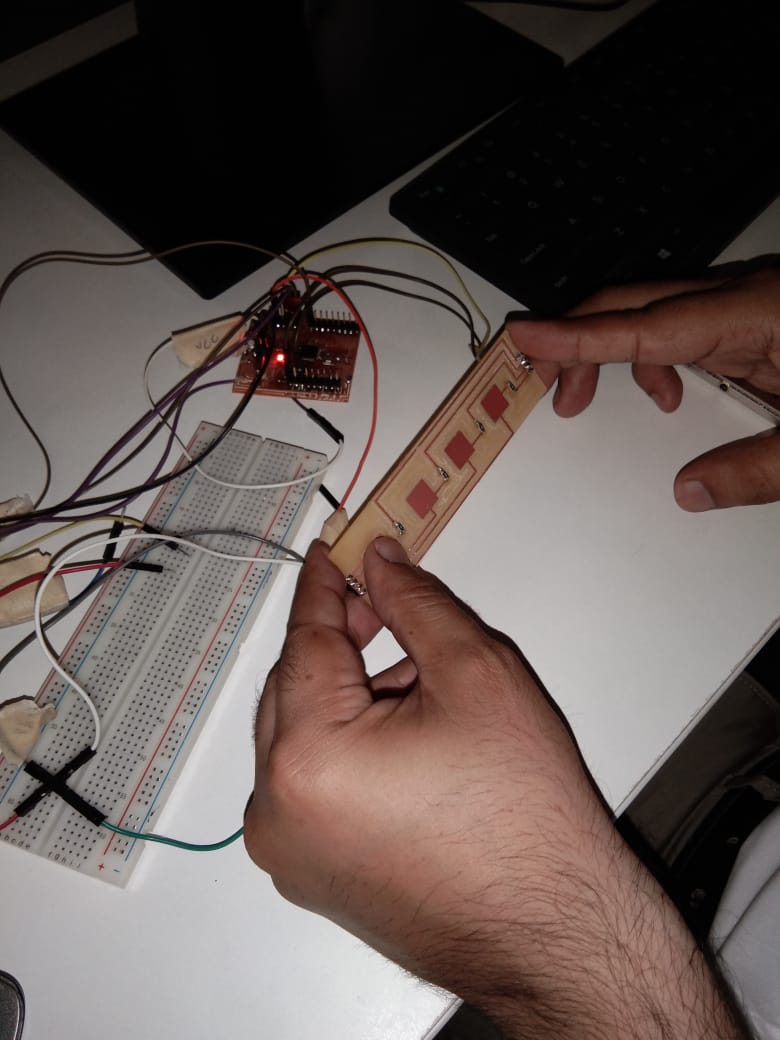
Let's Try
I tried Differnt ways to achive my desied output ,like in above video I programmed board in such way that when user touch the button and it show B1=1 and when user does not touch it show B1=0 on serial mointor.
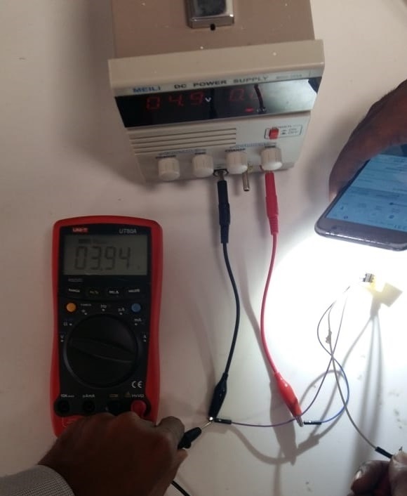
This week's group assignment was to detect the analogue and digital levels of input device we made individually so we started to measure the anlogue voltage levels of photo transitor which was used by me in this week's assignment. In group assignment we measured the voltage levels of this component which changes whenever we increase or decrease the intensity of lights on it. We connected the sensor module to 5 voltage and checked the output on data pin and ground using multimeter. We observed that whenever we increase the intensity of light voltages increase and whenever we decrease intensity of light voltage decrease. Both of the experiments are shown below in figures (a) and (b) respectively.
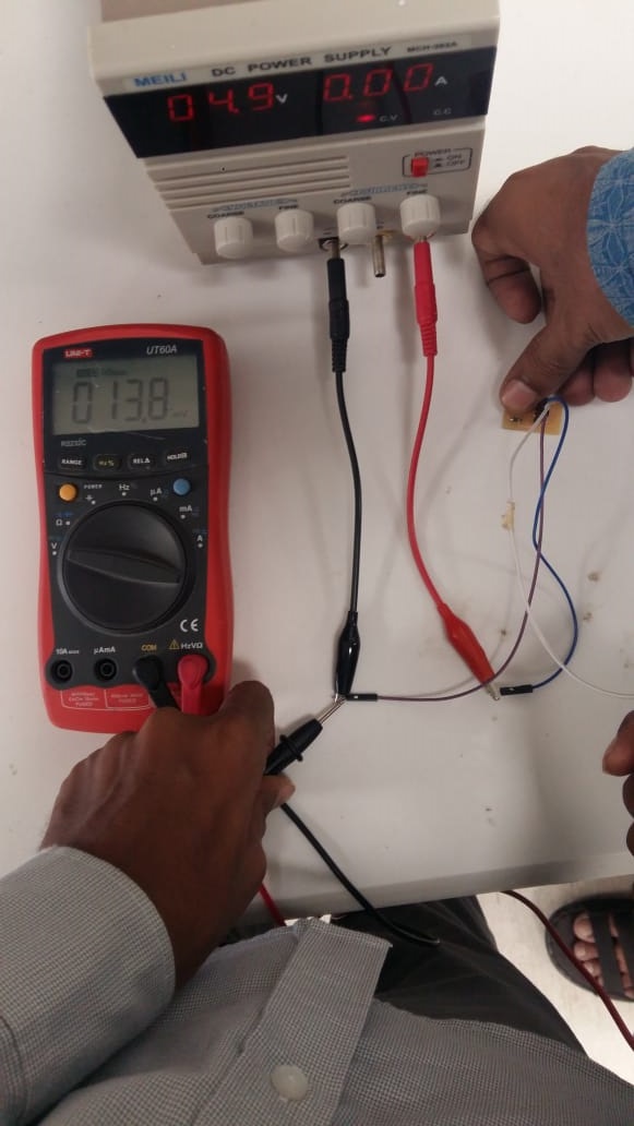
Measuring Voltage levels with low intensity of ligh
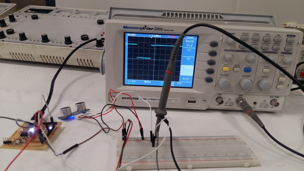
HC SR-04 Ultrasonic sensor is used by one of our group member in his individual task of this week so we used that sensor for detecting the digital signals. We have detected the change in digital signal in Oscilloscope using arduino Leonardo. A sensor is connected with arduino and the pin of Echo is connected with Oscilloscope. Arduino Leonardo is programmed to detect obstacle in front of Ultrasonic sensor, when an obstacle is present in front of Ultrasonic sensor we found change in wave in oscilloscope. The captured digital signal of ultrasonic sensor is shown below in figure. Furthermore the echo pin of sensor is connected to the pin 13 of leonardo which is also connected to led of board. The video given below shows that whenever there is change in signal led is blinking. The rate of led blink is very fast because digital signal is changing fastly.
Click Here For Downloading this Week files
.png)