Design, build, and connect wired or wireless node(s) with network or bus addresses
send a message between two projects
ESP-12E is a miniature Wi-Fi module present in the market and is used for establishing a wireless network connection for microcontroller or processor.
The core of ESP-12E is ESP8266EX, which is a high integration wireless SoC (System on Chip). It features ability to embed Wi-Fi capabilities to systems or
to function as a standalone application. It is a low cost solution for developing IoT applications.Source
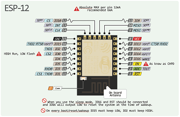
ESP-12E Pin Description
For PCB designing I worked on Eagle 7.5 First I made a schematic of board:
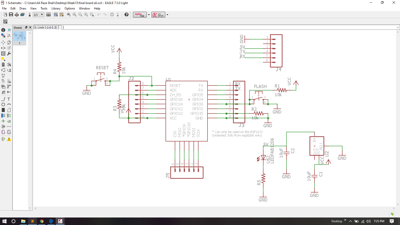
ESP-12E Board Schematic
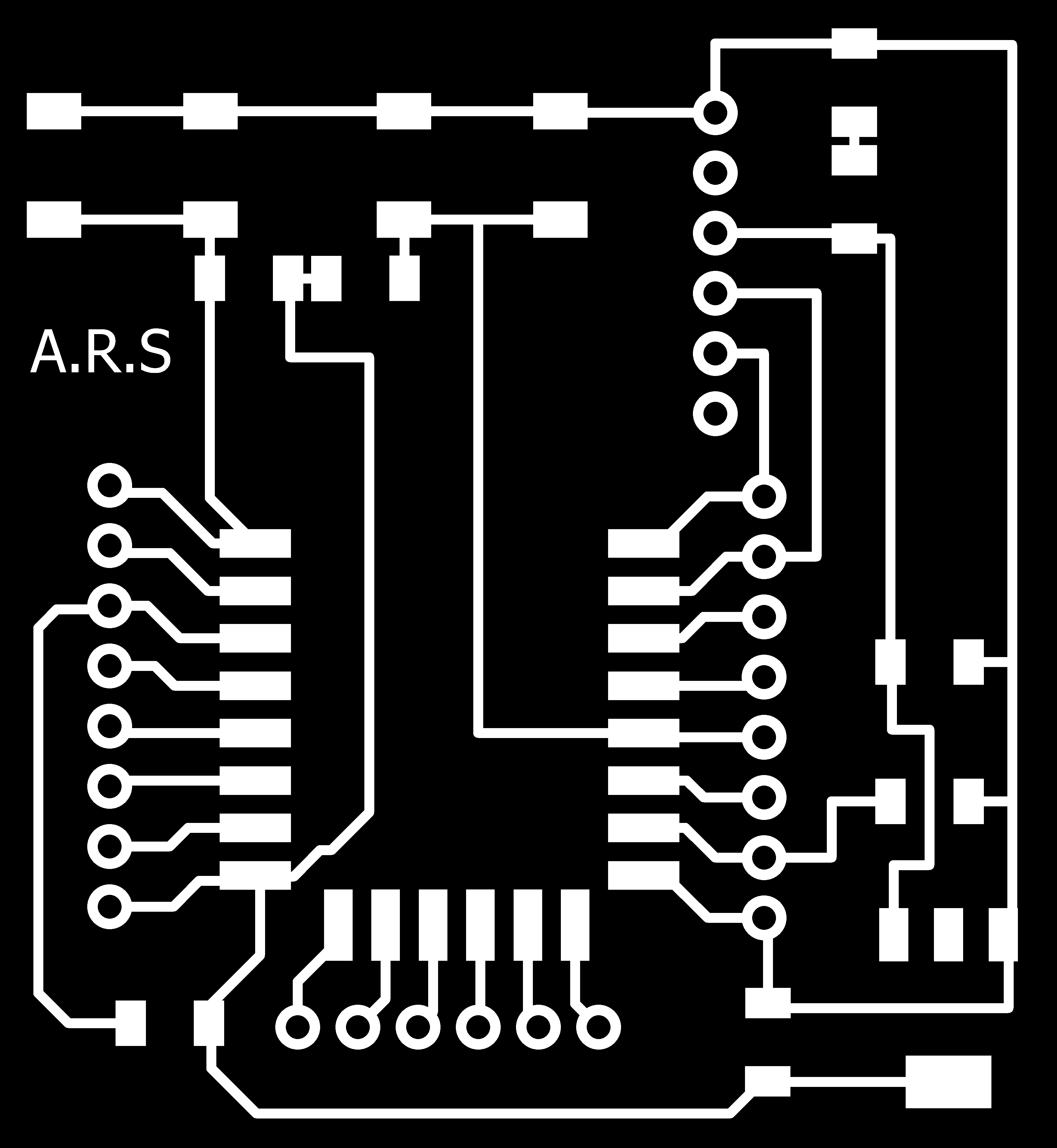
After Schmatic I generate PCB board and route it.
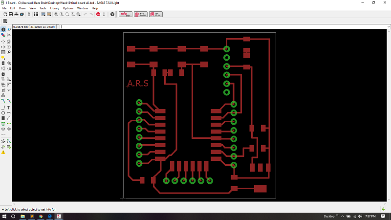
ESP-12E Board
For generating RML files, first I need my PCB design in .png format for that I export my PCB design in .png while setting up 2000 dpi and Monochrome
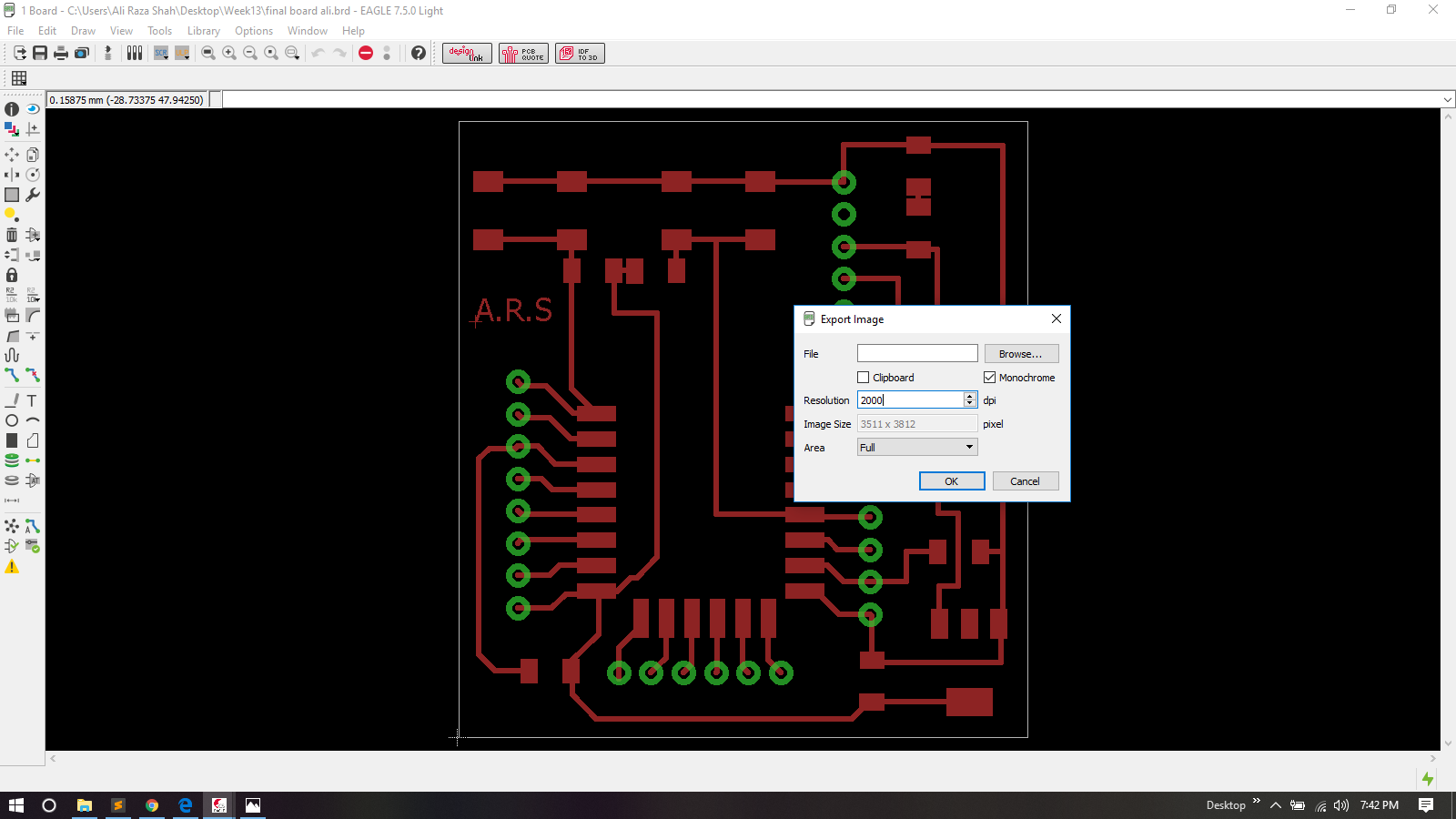
Exporting PCB design into .png format
.png is processed in Paint for making seperate files for traces, outline and drill holes of a PCB design
PCB Trace

PCB outline

Holes
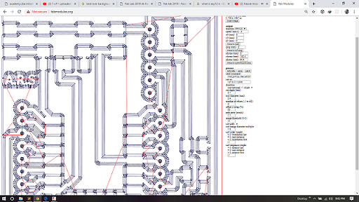
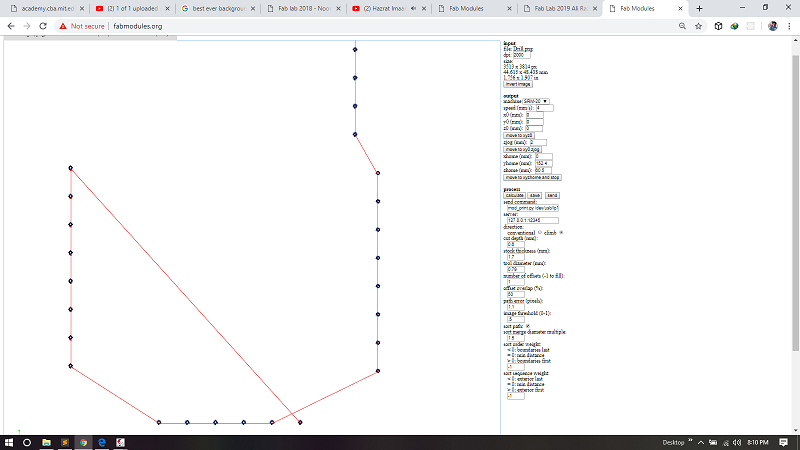
After making traces, outline and drill holes of pcb I used fabmodules to generate RML files of both traces and outline, all important settings are mentioned in a pictures below, for detailed fabmodules settings visit Electronics Production Week
Generating .rml file of PCB traces
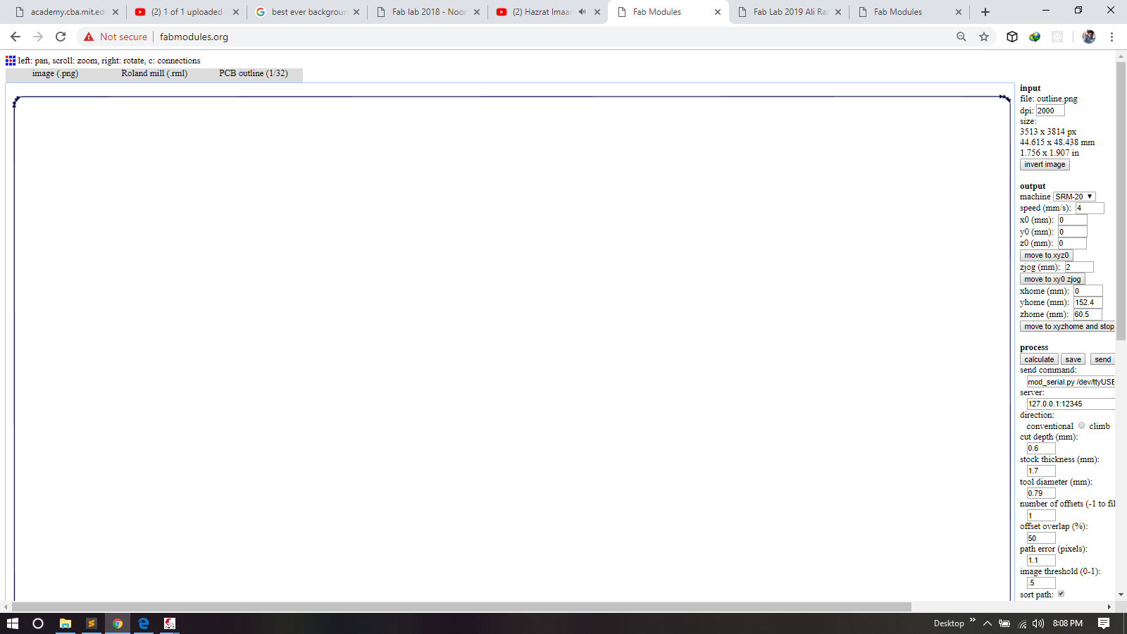
Generating .rml file of PCB outline
Generating .rml file of PCB drill Holes
.rml files are given to Roland SRM-20 for milling, 1/32 drill bit is used for cutting outlines and for drill holes, and 1/64 bit drill is used to make a trace on a board and here is the result.
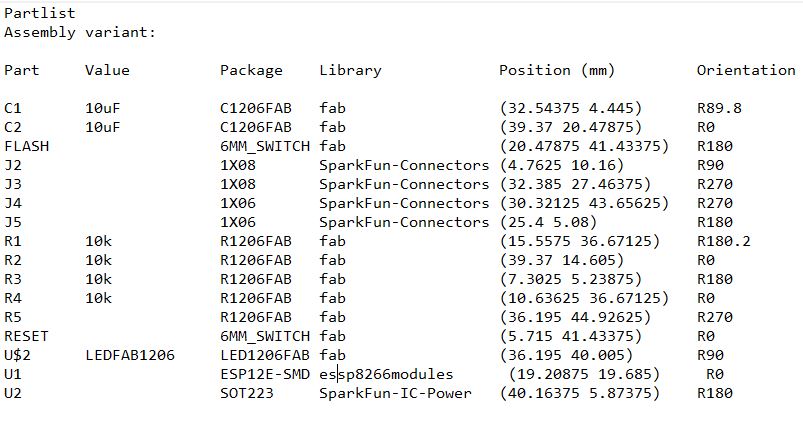
List Of Compoents
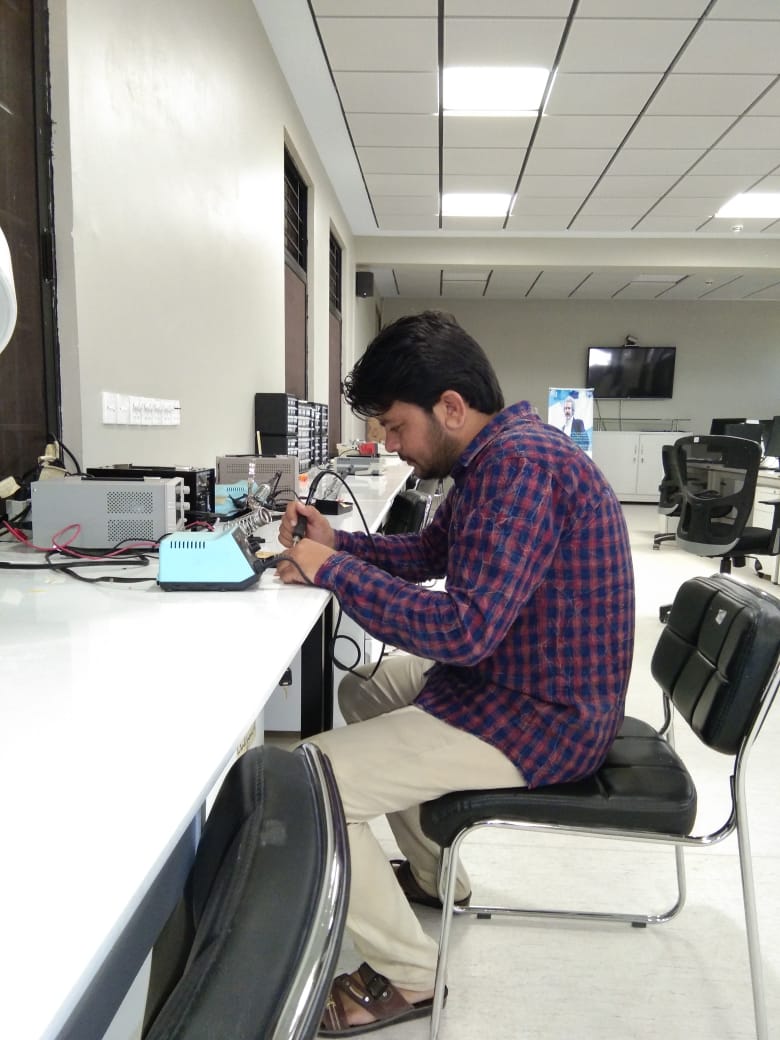
Soldering
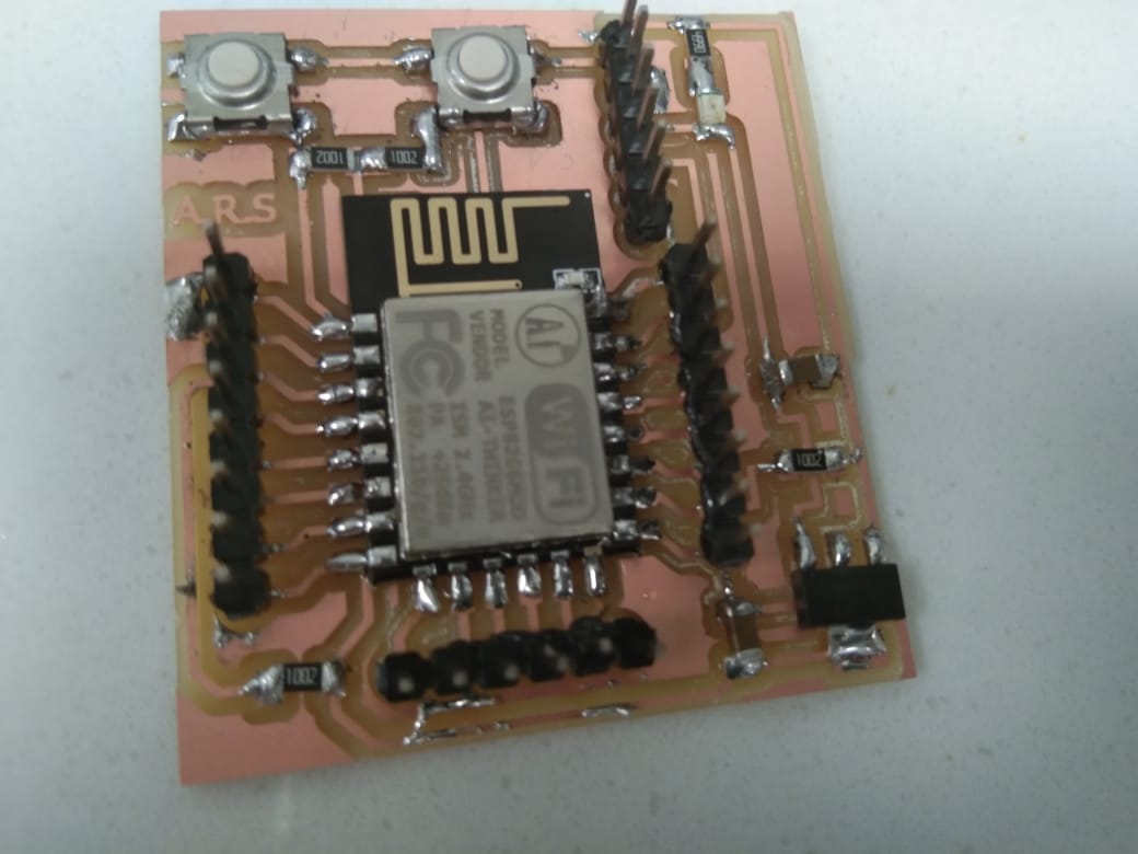
Soldered and ready to burn board
After soldering the next step is programming the board .I configure esp8266 tcp server, and download Tcp Telenet Terminal Mobile application from Playstore.
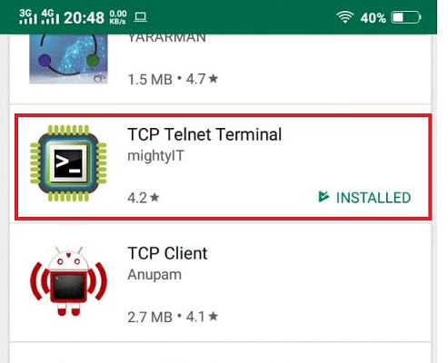
Download and Install TCP Client
After Downloading TCP client I programmed My Esp8266 in such way that it work like Access point or TCP server, and tcp client get IP Address that is offered by TCP server and make connection with server and start two way communication with each other.
\Initially I faced error realted to wifi library.I did not add Wifi library and continue uploading code. 😜
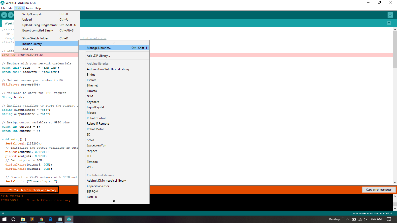
Library Error
After That I add Wifi Libray
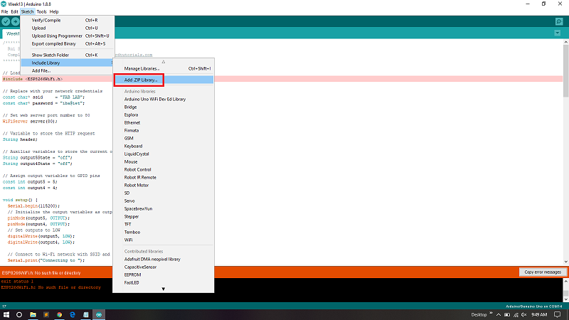
Add Zip File
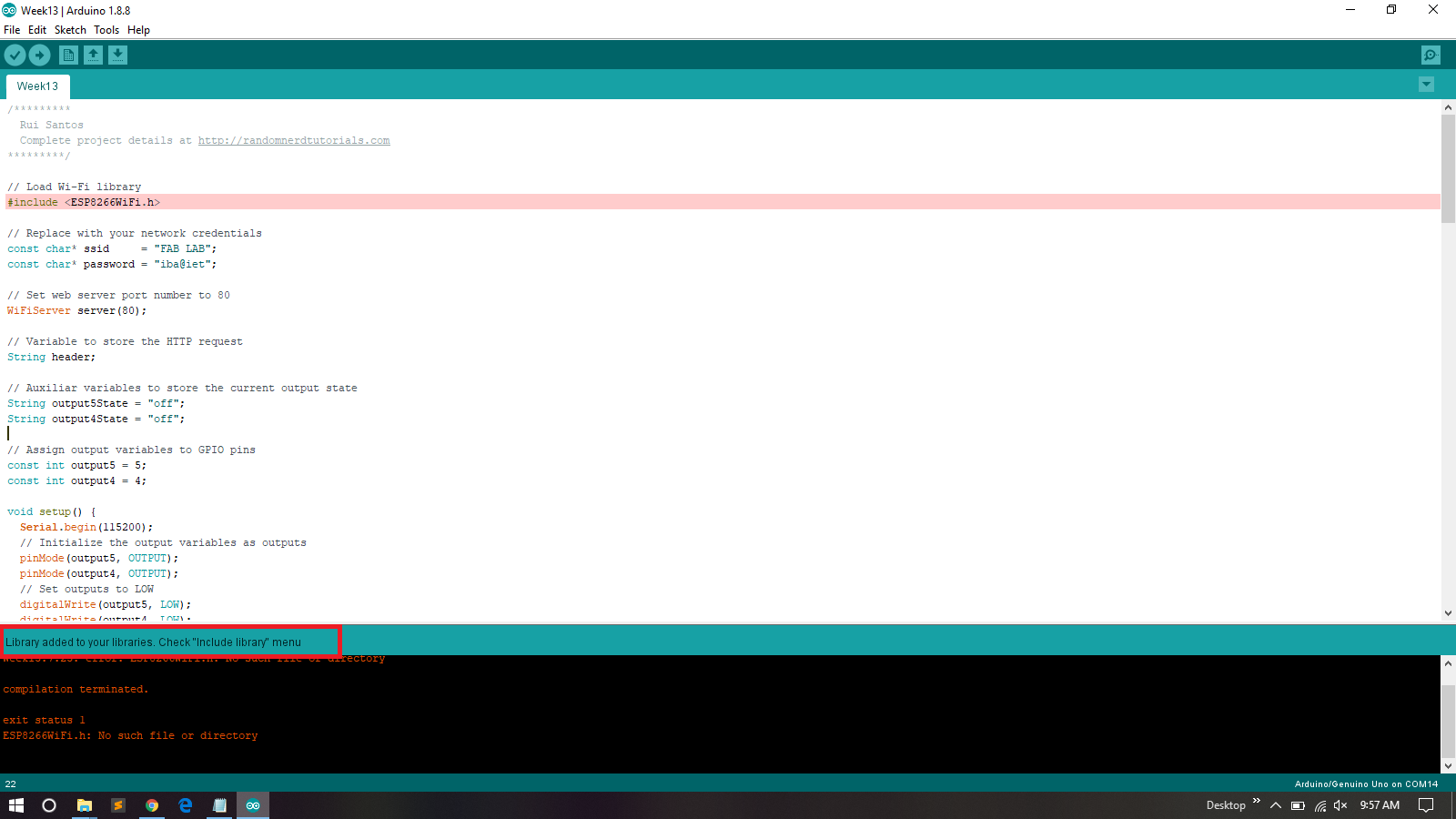
Included
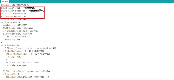
Set SSID , Password and PORT Number
I Define my SSID , pasword and pot Number of the local aera network , and client must be connected to same network if client connected with other network then communication between Server and client is not possible.
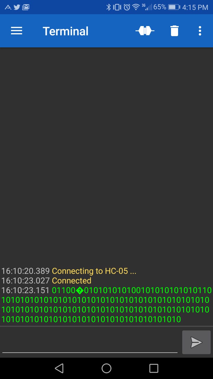
As a group assignment this week we used HC05 bluottoth module, connected it to atinny44. We then communicated with two slaves (slave 2 was atinny 44 with address 27 and slave 1 was atinny45 with address 26) making 328p the master. Hence led blinking every for one mili second shows the reception of data. Data here is just 0 and 1, and so led will just blink for 100ms. Connection can be seen below.
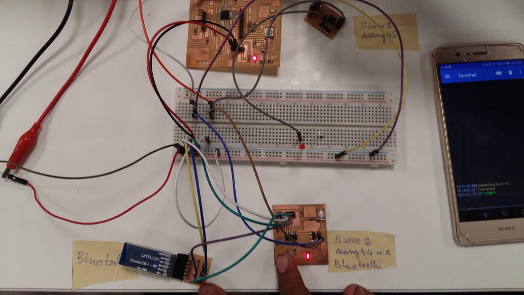
Next we used terminal as to see data received..
Below attached video illustrates working network. Note: Led on breadboard is attached to slave atinny45 as it did't have any builtin led.
You May Download This Week files from Here
.png)